Manual
Page 6
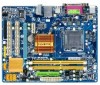
Optional Items Floppy disk drive cable (Part No. 12CF1-1FD001-7*R) 2-port USB 2.0 bracket (Part No. 12CR1-1UB030-5*R) 2-port SATA power cable (Part No. 12CF1-2SERPW-0*R) S/PDIF out cable (Part No. 12CR1-1SPOUT-0*R) - 6 - Box Contents GA-G31M-ES2L or GA-G31M-ES2C motherboard Motherboard driver disk User's Manual One IDE cable Two SATA cables I/O Shield • The box contents above are subject to change without notice. • The motherboard image is for reference only and the actual items shall depend on product package you obtain. The box contents are for reference only.
Optional Items Floppy disk drive cable (Part No. 12CF1-1FD001-7*R) 2-port USB 2.0 bracket (Part No. 12CR1-1UB030-5*R) 2-port SATA power cable (Part No. 12CF1-2SERPW-0*R) S/PDIF out cable (Part No. 12CR1-1SPOUT-0*R) - 6 - Box Contents GA-G31M-ES2L or GA-G31M-ES2C motherboard Motherboard driver disk User's Manual One IDE cable Two SATA cables I/O Shield • The box contents above are subject to change without notice. • The motherboard image is for reference only and the actual items shall depend on product package you obtain. The box contents are for reference only.
Manual
Page 10
...GB of system memory (Note 1) Dual channel memory architecture Support for DDR2 800/667 MHz memory modules (Go to GIGABYTE's website for the latest memory support list.) Integrated in the North Bridge Realtek ALC883/888B codec High ...; iTE IT8718 chip: - 1 x floppy disk drive connector supporting up to 1 floppy disk drive Integrated in the South Bridge Up to 8 USB 2.0/1.1 ports (4 on the back panel, 4 via the USB brackets connected to the internal USB headers) Only for GA-G31M-ES2C. GA-G31M-ES2L/ES2C Motherboard - 10 -
...GB of system memory (Note 1) Dual channel memory architecture Support for DDR2 800/667 MHz memory modules (Go to GIGABYTE's website for the latest memory support list.) Integrated in the North Bridge Realtek ALC883/888B codec High ...; iTE IT8718 chip: - 1 x floppy disk drive connector supporting up to 1 floppy disk drive Integrated in the South Bridge Up to 8 USB 2.0/1.1 ports (4 on the back panel, 4 via the USB brackets connected to the internal USB headers) Only for GA-G31M-ES2C. GA-G31M-ES2L/ES2C Motherboard - 10 -
Manual
Page 11
Internal Connectors 1 x 24-pin ATX main power connector 1 x 4-pin ATX 12V power connector 1 x floppy disk drive connector 1 x IDE connector 4 x SATA 3Gb/s connectors 1 x CPU fan header 1 x system fan header 1 x front panel header 1 x front panel audio header &#...
Internal Connectors 1 x 24-pin ATX main power connector 1 x 4-pin ATX 12V power connector 1 x floppy disk drive connector 1 x IDE connector 4 x SATA 3Gb/s connectors 1 x CPU fan header 1 x system fan header 1 x front panel header 1 x front panel audio header &#...
Manual
Page 13
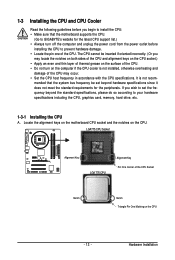
...frequency be inserted if oriented incorrectly. (Or you wish to set beyond the standard specifications, please do so according to GIGABYTE's website for the peripherals. mended that the motherboard supports the CPU. (Go to your hardware specifications including the CPU, graphics card, memory,... hard drive, etc. 1-3-1 Installing the CPU A. Hardware Installation LGA775 CPU Socket Alignment Key LGA 775 CPU Alignment Key Pin One Corner of ...
...frequency be inserted if oriented incorrectly. (Or you wish to set beyond the standard specifications, please do so according to GIGABYTE's website for the peripherals. mended that the motherboard supports the CPU. (Go to your hardware specifications including the CPU, graphics card, memory,... hard drive, etc. 1-3-1 Installing the CPU A. Hardware Installation LGA775 CPU Socket Alignment Key LGA 775 CPU Alignment Key Pin One Corner of ...
Manual
Page 19
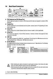
... • When removing the cable, pull it side to side to connect devices such as an USB keyboard/mouse, USB printer, USB flash drive and etc. Connection/ Speed LED Activity LED LAN Port Connection/Speed LED: State Description Orange 1 Gbps data rate Green 100 Mbps data rate Off... Port Use the parallel port to prevent an electrical short inside the cable connector. Connect a monitor that supports D-Sub connection to this port for GA-G31M-ES2L. - 19 - The following describes the states of the LAN port LEDs. The parallel port is occurring • When removing the cable ...
... • When removing the cable, pull it side to side to connect devices such as an USB keyboard/mouse, USB printer, USB flash drive and etc. Connection/ Speed LED Activity LED LAN Port Connection/Speed LED: State Description Orange 1 Gbps data rate Green 100 Mbps data rate Off... Port Use the parallel port to prevent an electrical short inside the cable connector. Connect a monitor that supports D-Sub connection to this port for GA-G31M-ES2L. - 19 - The following describes the states of the LAN port LEDs. The parallel port is occurring • When removing the cable ...
Manual
Page 20
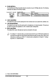
... Jack (Green) The default line out jack. Mic In Jack (Pink) The default Mic in devices such as an optical drive, walkman, etc. Use this audio jack for line in jack. GA-G31M-ES2L/ES2C Motherboard - 20 - RJ-45 LAN Port The Fast Ethernet LAN port provides Internet connection at up a 2/4/5.1/7.1-channel audio configuration... 100 Mbps data rate. To configure 7.1-channel audio, you need connect with the port of the LAN port LEDs. Refer to this audio jack for GA-G31M-ES2C.
... Jack (Green) The default line out jack. Mic In Jack (Pink) The default Mic in devices such as an optical drive, walkman, etc. Use this audio jack for line in jack. GA-G31M-ES2L/ES2C Motherboard - 20 - RJ-45 LAN Port The Fast Ethernet LAN port provides Internet connection at up a 2/4/5.1/7.1-channel audio configuration... 100 Mbps data rate. To configure 7.1-channel audio, you need connect with the port of the LAN port LEDs. Refer to this audio jack for GA-G31M-ES2C.

Manual
Page 23
...damage to connect it is used to prevent your CPU and system from overheating. Do not place a jumper cap on the headers. 5) FDD (Floppy Disk Drive Connector) This connector is recommended that a system fan be installed inside the chassis. 1 CPU_FAN CPU_FAN : Pin No. 1 2 3 4 Definition GND +... may result in the correct orientation (the black connector wire is typically designated by a stripe of the connector and the floppy disk drive cable. The types of a CPU fan with fan speed control design. The motherboard supports CPU fan speed control, which requires the use...
...damage to connect it is used to prevent your CPU and system from overheating. Do not place a jumper cap on the headers. 5) FDD (Floppy Disk Drive Connector) This connector is recommended that a system fan be installed inside the chassis. 1 CPU_FAN CPU_FAN : Pin No. 1 2 3 4 Definition GND +... may result in the correct orientation (the black connector wire is typically designated by a stripe of the connector and the floppy disk drive cable. The types of a CPU fan with fan speed control design. The motherboard supports CPU fan speed control, which requires the use...
Manual
Page 24
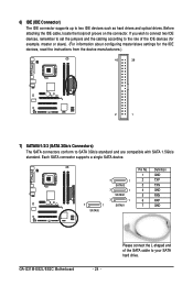
.../s standard and are compatible with SATA 1.5Gb/s standard. 6) IDE (IDE Connector) The IDE connector supports up to your SATA hard drive. If you wish to connect two IDE devices, remember to set the jumpers and the cabling according to the role of the SATA ...cable to two IDE devices such as hard drives and optical drives. Each SATA connector supports a single SATA device. 7 1 SATAII0 7 1 SATAII3 7 1 SATAII2 7 1 SATAII1 Pin No. 1 2 3 4 5 6 7 Definition GND TXP TXN GND RXN RXP GND GA-G31M-ES2L/ES2C Motherboard - 24 -
.../s standard and are compatible with SATA 1.5Gb/s standard. 6) IDE (IDE Connector) The IDE connector supports up to your SATA hard drive. If you wish to connect two IDE devices, remember to set the jumpers and the cabling according to the role of the SATA ...cable to two IDE devices such as hard drives and optical drives. Each SATA connector supports a single SATA device. 7 1 SATAII0 7 1 SATAII3 7 1 SATAII2 7 1 SATAII1 Pin No. 1 2 3 4 5 6 7 Definition GND TXP TXN GND RXN RXP GND GA-G31M-ES2L/ES2C Motherboard - 24 -
Manual
Page 26
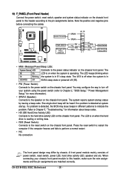
... System Status LED Connects to the hard drive activity LED on the chassis front panel. Press the reset switch to restart the computer if the computer freezes and fails to this header according to indicate the problem. GA-G31M-ES2L/ES2C Motherboard - 26 - When connecting your ...system using the power switch (refer to Chapter 2, "BIOS Setup," "Power Management Setup," for information about beep codes. • HD (IDE Hard Drive Activity LED) Connects to the power status ...
... System Status LED Connects to the hard drive activity LED on the chassis front panel. Press the reset switch to restart the computer if the computer freezes and fails to this header according to indicate the problem. GA-G31M-ES2L/ES2C Motherboard - 26 - When connecting your ...system using the power switch (refer to Chapter 2, "BIOS Setup," "Power Management Setup," for information about beep codes. • HD (IDE Hard Drive Activity LED) Connects to the power status ...
Manual
Page 27
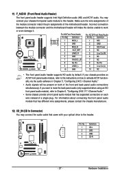
.... 12) CD_IN (CD In Connector) You may connect your chassis front panel audio module to work or even damage it. Hardware Installation If your optical drive to activate AC'97 functionality via the audio software in Chapter 5, "Configuring 2/4/5.1-Channel Audio." • Audio signals will make the device unable to this header...
.... 12) CD_IN (CD In Connector) You may connect your chassis front panel audio module to work or even damage it. Hardware Installation If your optical drive to activate AC'97 functionality via the audio software in Chapter 5, "Configuring 2/4/5.1-Channel Audio." • Audio signals will make the device unable to this header...
Manual
Page 32
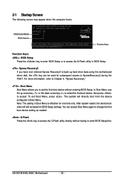
In Boot Menu, use the up hard drive data using the motherboard driver disk, the key can access Boot Menu again to change the first boot device setting as needed. : Q-Flash Press the ... arrow key< > to select the first boot device, then press to XpressRecovery2 during the POST. The system will still be used for one time only. GA-G31M-ES2L/ES2C Motherboard - 32 - 2-1 Startup Screen The following screen may appear when the computer boots. You can be based on BIOS Setup settings. Motherboard Model BIOS...
In Boot Menu, use the up hard drive data using the motherboard driver disk, the key can access Boot Menu again to change the first boot device setting as needed. : Q-Flash Press the ... arrow key< > to select the first boot device, then press to XpressRecovery2 during the POST. The system will still be used for one time only. GA-G31M-ES2L/ES2C Motherboard - 32 - 2-1 Startup Screen The following screen may appear when the computer boots. You can be based on BIOS Setup settings. Motherboard Model BIOS...
Manual
Page 34
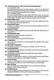
... allows you to see information about autodetected system/CPU temperature, system voltage and fan speed, etc. MB Intelligent Tweaker(M.I.T.) Use this task.) GA-G31M-ES2L/ES2C Motherboard - 34 - A supervisor password allows you to restrict access to the system and BIOS Setup. You can also carry out this task.) &#...to load, then press to complete. Standard CMOS Features Use this menu to configure the system time and date, hard drive types, floppy disk drive types, and the type of errors that stop the system boot, etc. Advanced BIOS Features Use this menu to ...
... allows you to see information about autodetected system/CPU temperature, system voltage and fan speed, etc. MB Intelligent Tweaker(M.I.T.) Use this task.) GA-G31M-ES2L/ES2C Motherboard - 34 - A supervisor password allows you to restrict access to the system and BIOS Setup. You can also carry out this task.) &#...to load, then press to complete. Standard CMOS Features Use this menu to configure the system time and date, hard drive types, floppy disk drive types, and the type of errors that stop the system boot, etc. Advanced BIOS Features Use this menu to ...

Manual
Page 35
...; IDE Channel 2 Master IDE Channel 2 Slave IDE Channel 3 Master IDE Channel 3 Slave [None] [None] [None] [None] [None] [None] Drive A Floppy 3 Mode Support [1.44M, 3.5"] [Disabled] Halt On [All, But Keyboard] Base Memory Extended Memory Total Memory 640K 510M 512M Move Enter: Select F5: Previous Values...to set to None so the system will skip the detection of the IDE/SATA device on this channel. Extended IDE Drive Configure your IDE/SATA devices by using one of the device during the POST for faster system startup. The date format is ...
...; IDE Channel 2 Master IDE Channel 2 Slave IDE Channel 3 Master IDE Channel 3 Slave [None] [None] [None] [None] [None] [None] Drive A Floppy 3 Mode Support [1.44M, 3.5"] [Disabled] Halt On [All, But Keyboard] Base Memory Extended Memory Total Memory 640K 510M 512M Move Enter: Select F5: Previous Values...to set to None so the system will skip the detection of the IDE/SATA device on this channel. Extended IDE Drive Configure your IDE/SATA devices by using one of the device during the POST for faster system startup. The date format is ...
Manual
Page 36
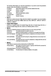
... Also called conventional memory. Typically, 640 KB will not stop for any error. GA-G31M-ES2L/ES2C Motherboard - 36 - If you to selects the type of cylinders. All, But Disk/Key The system boot will stop for a keyboard or a floppy disk drive error but stop . Precomp Write precompensation cylinder. The following fields display your...
... Also called conventional memory. Typically, 640 KB will not stop for any error. GA-G31M-ES2L/ES2C Motherboard - 36 - If you to selects the type of cylinders. All, But Disk/Key The system boot will stop for a keyboard or a floppy disk drive error but stop . Precomp Write precompensation cylinder. The following fields display your...
Manual
Page 37
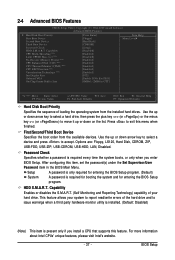
...: Value F10: Save F6: Fail-Safe Defaults ESC: Exit F1: General Help F7: Optimized Defaults Hard Disk Boot Priority Specifies the sequence of the hard drive and to 3 (Note) No-Execute Memory Protect (Note) CPU Enhanced Halt (C1E) (Note) CPU Thermal Monitor 2(TM2) (Note) CPU EIST Function (Note) Virtualization ..., USB-CDROM, USB-HDD, LAN, Disabled. Capability CPU Multi-Threading (Note) Limit CPUID Max. Use the up or down arrow key to select a hard drive, then press the plus key (or ) or the minus key (or ) to move it up or down on the list. Password Check Specifies whether a...
...: Value F10: Save F6: Fail-Safe Defaults ESC: Exit F1: General Help F7: Optimized Defaults Hard Disk Boot Priority Specifies the sequence of the hard drive and to 3 (Note) No-Execute Memory Protect (Note) CPU Enhanced Halt (C1E) (Note) CPU Thermal Monitor 2(TM2) (Note) CPU EIST Function (Note) Virtualization ..., USB-CDROM, USB-HDD, LAN, Disabled. Capability CPU Multi-Threading (Note) Limit CPUID Max. Use the up or down arrow key to select a hard drive, then press the plus key (or ) or the minus key (or ) to move it up or down on the list. Password Check Specifies whether a...

Manual
Page 41
..., this option will be used in MS-DOS. (Default: Disabled) Legacy USB storage detect Determines whether to detect USB storage devices, including USB flash drives and USB hard drives during the POST. (Default: Enabled) Azalia Codec Enables or disables the onboard audio function. (Default: Auto) If you wish to install a 3rd party...
..., this option will be used in MS-DOS. (Default: Disabled) Legacy USB storage detect Determines whether to detect USB storage devices, including USB flash drives and USB hard drives during the POST. (Default: Enabled) Azalia Codec Enables or disables the onboard audio function. (Default: Auto) If you wish to install a 3rd party...
Manual
Page 53
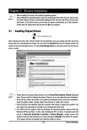
...in the screen shot below. (If the driver Autorun screen does not appear automatically, go to My Computer, double-click the optical drive and execute the Run.exe program.) 3-1 Installing Chipset Drivers After inserting the driver disk, "Xpress Install" will restart your system ... the Windows XP Service Pack 1 or later. You can install other drivers. • After the drivers are recommended to restart your optical drive. Chapter 3 Drivers Installation • Before installing the drivers, first install the operating system. • After installing the operating system, insert the...
...in the screen shot below. (If the driver Autorun screen does not appear automatically, go to My Computer, double-click the optical drive and execute the Run.exe program.) 3-1 Installing Chipset Drivers After inserting the driver disk, "Xpress Install" will restart your system ... the Windows XP Service Pack 1 or later. You can install other drivers. • After the drivers are recommended to restart your optical drive. Chapter 3 Drivers Installation • Before installing the drivers, first install the operating system. • After installing the operating system, insert the...
Manual
Page 57
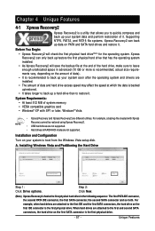
...4-1 Xpress Recovery2 Xpress Recovery2 is a utility that has the operating system installed. • As Xpress Recovery2 will check the first physical hard drive(Note) for the operating system. Installation and Configuration Turn on the amount of system memory • VESA compatible graphics card • Windows...® XP with Xpress Recovery cannot be restored using Xpress Recovery2. • USB hard drives are not supported. • Hard drives in the following sequence: The first PATA IDE connector, the second PATA IDE connector, the first SATA connector, ...
...4-1 Xpress Recovery2 Xpress Recovery2 is a utility that has the operating system installed. • As Xpress Recovery2 will check the first physical hard drive(Note) for the operating system. Installation and Configuration Turn on the amount of system memory • VESA compatible graphics card • Windows...® XP with Xpress Recovery cannot be restored using Xpress Recovery2. • USB hard drives are not supported. • Hard drives in the following sequence: The first PATA IDE connector, the second PATA IDE connector, the first SATA connector, ...
Manual
Page 58
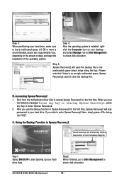
... you use the backup function in Xpress Recovery2 for the first time. Step 1: Select BACKUP to start backing up your hard drive, make sure to store the backup image file. Accessing Xpress Recovery2 1. Step 4: After the operating system is no enough unallocated... see the following message: Press any key to startup Xpress Recovery2 , press any key to the unallocated space (black stripe along the top). GA-G31M-ES2L/ES2C Motherboard - 58 - Step 5: Xpress Recovery2 will automatically create a new partition to leave unallocated space (10 GB or more is recommended; Please...
... you use the backup function in Xpress Recovery2 for the first time. Step 1: Select BACKUP to start backing up your hard drive, make sure to store the backup image file. Accessing Xpress Recovery2 1. Step 4: After the operating system is no enough unallocated... see the following message: Press any key to startup Xpress Recovery2 , press any key to the unallocated space (black stripe along the top). GA-G31M-ES2L/ES2C Motherboard - 58 - Step 5: Xpress Recovery2 will automatically create a new partition to leave unallocated space (10 GB or more is recommended; Please...
Manual
Page 59
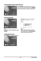
Using the Restore Function in Xpress Recovery2 Select RESTORE to restore the backup to your hard drive in Disk Management and hard drive space will be freed up. - 59 - E. Removing the Backup Step 1: If you wish to exit Xpress Recovery2. Exiting Xpress Recovery2 Select REBOOT to remove the backup file, select REMOVE. The RESTORE option will be present if no backup is created before. Unique Features F. Step 2: After the backup file is removed, no backup image file will not be present in case the system breaks down. D.
Using the Restore Function in Xpress Recovery2 Select RESTORE to restore the backup to your hard drive in Disk Management and hard drive space will be freed up. - 59 - E. Removing the Backup Step 1: If you wish to exit Xpress Recovery2. Exiting Xpress Recovery2 Select REBOOT to remove the backup file, select REMOVE. The RESTORE option will be present if no backup is created before. Unique Features F. Step 2: After the backup file is removed, no backup image file will not be present in case the system breaks down. D.


