Manual
Page 3
...product information, carefully read or download the information on/from the Support\Motherboard\Technology Guide page on your motherboard revision before updating motherboard BIOS, drivers, or when looking for technical information. For example, "REV: 1.0" means the revision of this manual may be reproduced,...this manual are legally registered to assist in this manual is 1.0. Copyright © 2009 GIGA-BYTE TECHNOLOGY CO., LTD. Changes to use GIGABYTE's unique features, read the User's Manual. For instructions on how to the specifications and features in this : "REV: ...
...product information, carefully read or download the information on/from the Support\Motherboard\Technology Guide page on your motherboard revision before updating motherboard BIOS, drivers, or when looking for technical information. For example, "REV: 1.0" means the revision of this manual may be reproduced,...this manual are legally registered to assist in this manual is 1.0. Copyright © 2009 GIGA-BYTE TECHNOLOGY CO., LTD. Changes to use GIGABYTE's unique features, read the User's Manual. For instructions on how to the specifications and features in this : "REV: ...

Manual
Page 4
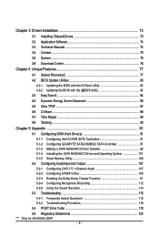
Table of Contents Box Contents ...6 Optional Items...6 GA-EX58-UD5P/GA-EX58-UD5 Motherboard Layout 7 Block Diagram...8 Chapter 1 Hardware Installation 9 1-1 Installation Precautions 9 1-2 Product Specifications 10 1-3 Installing the CPU and CPU Cooler 13 ... Panel Connectors 23 1-9 Onboard LEDs and Switches 25 1-10 Internal Connectors 27 Chapter 2 BIOS Setup 41 2-1 Startup Screen 42 2-2 The Main Menu 43 2-3 MB Intelligent Tweaker(M.I.T 45 2-4 Standard CMOS Features 55 2-5 Advanced BIOS Features 57 2-6 Integrated Peripherals 59 2-7 Power Management Setup 64 2-8 PC Health Status 66...
Table of Contents Box Contents ...6 Optional Items...6 GA-EX58-UD5P/GA-EX58-UD5 Motherboard Layout 7 Block Diagram...8 Chapter 1 Hardware Installation 9 1-1 Installation Precautions 9 1-2 Product Specifications 10 1-3 Installing the CPU and CPU Cooler 13 ... Panel Connectors 23 1-9 Onboard LEDs and Switches 25 1-10 Internal Connectors 27 Chapter 2 BIOS Setup 41 2-1 Startup Screen 42 2-2 The Main Menu 43 2-3 MB Intelligent Tweaker(M.I.T 45 2-4 Standard CMOS Features 55 2-5 Advanced BIOS Features 57 2-6 Integrated Peripherals 59 2-7 Power Management Setup 64 2-8 PC Health Status 66...
Manual
Page 5
...Q-Flash Utility 80 4-2-2 Updating the BIOS with the @BIOS Utility 83 4-3 EasyTune 6...84 4-4 Dynamic Energy Saver Advanced 85 4-5 Ultra TPM* ...87 4-6 Q-Share ...88 4-7 Time Repair ...89 4-8 Teaming ...90 Chapter 5 Appendix ...91 5-1 Configuring SATA Hard Drive(s 91 5-1-1 Configuring Intel ICH10R SATA Controllers 91 5-1-2 Configuring GIGABYTE SATA2/JMB322 SATA Controller 97 5-1-3 ... Sound Recorder 114 5-3 Troubleshooting 115 5-3-1 Frequently Asked Questions 115 5-3-2 Troubleshooting Procedure 116 5-4 POST Error Code 118 5-5 Regulatory Statements 122 "*" Only for GA-EX58-UD5P. - 5 -
...Q-Flash Utility 80 4-2-2 Updating the BIOS with the @BIOS Utility 83 4-3 EasyTune 6...84 4-4 Dynamic Energy Saver Advanced 85 4-5 Ultra TPM* ...87 4-6 Q-Share ...88 4-7 Time Repair ...89 4-8 Teaming ...90 Chapter 5 Appendix ...91 5-1 Configuring SATA Hard Drive(s 91 5-1-1 Configuring Intel ICH10R SATA Controllers 91 5-1-2 Configuring GIGABYTE SATA2/JMB322 SATA Controller 97 5-1-3 ... Sound Recorder 114 5-3 Troubleshooting 115 5-3-1 Frequently Asked Questions 115 5-3-2 Troubleshooting Procedure 116 5-4 POST Error Code 118 5-5 Regulatory Statements 122 "*" Only for GA-EX58-UD5P. - 5 -
Manual
Page 8
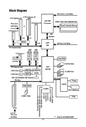
... PCIe CLK (100 MHz) x1 LAN2 LAN1 RJ45 RJ45 RTL RTL 8111D 8111D x1 x1 PCI Express Bus 2 SATA 3Gb/s 2 SATA 3Gb/s JMB322 JMB322 x1 GIGABYTE SATA2 ATA-133/100/66/33 IDE Channel PCI Bus TSB43AB23 QPI Interface Intel® X58 IOH CLK (133 MHz) Intel® ICH10R Dual... BIOS 6 SATA 3Gb/s 12 USB Ports CODEC LPC Bus IT8720 Floppy PS/2 KB/Mouse 3 IEEE 1394a TPM* Surround Speaker Out Center/Subwoofer Speaker Out Side Speaker ...
... PCIe CLK (100 MHz) x1 LAN2 LAN1 RJ45 RJ45 RTL RTL 8111D 8111D x1 x1 PCI Express Bus 2 SATA 3Gb/s 2 SATA 3Gb/s JMB322 JMB322 x1 GIGABYTE SATA2 ATA-133/100/66/33 IDE Channel PCI Bus TSB43AB23 QPI Interface Intel® X58 IOH CLK (133 MHz) Intel® ICH10R Dual... BIOS 6 SATA 3Gb/s 12 USB Ports CODEC LPC Bus IT8720 Floppy PS/2 KB/Mouse 3 IEEE 1394a TPM* Surround Speaker Out Center/Subwoofer Speaker Out Side Speaker ...
Manual
Page 12
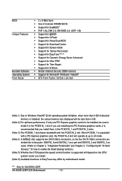
GA-EX58-UD5P/UD5 Motherboard - 12 - "*" Only for how to enable the Smart Backup function.) (Note 5) Whether the CPU/system fan speed control function is supported will operate at ... Software Operating System Form Factor 2 x 8 Mbit flash Use of licensed AWARD BIOS Support for DualBIOSTM PnP 1.0a, DMI 2.0, SM BIOS 2.4, ACPI 1.0b Support for @BIOS Support for Q-Flash Support for Virtual Dual BIOS Support for Download Center Support for Xpress Install Support for Xpress...
GA-EX58-UD5P/UD5 Motherboard - 12 - "*" Only for how to enable the Smart Backup function.) (Note 5) Whether the CPU/system fan speed control function is supported will operate at ... Software Operating System Form Factor 2 x 8 Mbit flash Use of licensed AWARD BIOS Support for DualBIOSTM PnP 1.0a, DMI 2.0, SM BIOS 2.4, ACPI 1.0b Support for @BIOS Support for Q-Flash Support for Virtual Dual BIOS Support for Download Center Support for Xpress Install Support for Xpress...

Manual
Page 16
...When enabling 3 Channel mode with three, four or six modules, it is installed, the BIOS will appear during the POST. Intel ® Flex Memory Technology offers greater flexibility to upgrade...- 3 Channel Memory Configurations Table DDR3_2 DDR3_1 DDR3_4 DDR3_3 DDR3_6 DDR3_5 Three Modules Four Modules Six Modules - GA-EX58-UD5P/UD5 Motherboard - 16 - DS/SS - - - - Dual Channel-1. When enabling Dual Channel mode with four...memory of the same capacity, brand, speed, and chips be used . (Go to GIGABYTE's website for the latest memory support list.) • Always turn off the computer ...
...When enabling 3 Channel mode with three, four or six modules, it is installed, the BIOS will appear during the POST. Intel ® Flex Memory Technology offers greater flexibility to upgrade...- 3 Channel Memory Configurations Table DDR3_2 DDR3_1 DDR3_4 DDR3_3 DDR3_6 DDR3_5 Three Modules Four Modules Six Modules - GA-EX58-UD5P/UD5 Motherboard - 16 - DS/SS - - - - Dual Channel-1. When enabling Dual Channel mode with four...memory of the same capacity, brand, speed, and chips be used . (Go to GIGABYTE's website for the latest memory support list.) • Always turn off the computer ...
Manual
Page 18
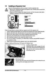
... bracket to the chassis back panel with the slot, and press down on your expansion card(s). 7. Install the driver provided with your operating system. GA-EX58-UD5P/UD5 Motherboard - 18 - Align the card with a screw. 5. Turn on the top edge of the PCI Express slot to release the card and ...then pull the card straight up from the slot. If necessary, go to BIOS Setup to make any required BIOS changes for your computer. 1-5 Installing an ...
... bracket to the chassis back panel with the slot, and press down on your expansion card(s). 7. Install the driver provided with your operating system. GA-EX58-UD5P/UD5 Motherboard - 18 - Align the card with a screw. 5. Turn on the top edge of the PCI Express slot to release the card and ...then pull the card straight up from the slot. If necessary, go to BIOS Setup to make any required BIOS changes for your computer. 1-5 Installing an ...
Manual
Page 33
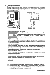
...panel. If a problem is in different patterns to indicate the problem. When connecting your system using the power switch (refer to Chapter 2, "BIOS Setup," "Power Management Setup," for information about beep codes. • HD (Hard Drive Activity LED, Blue) Connects to the hard drive ...and the pin assignments are matched correctly. - 33 - Hardware Installation The LED keeps blinking when S1 Blinking the system is detected, the BIOS may differ by issuing a beep code. The S0 On LED is detected at system startup. Note the positive and negative pins before connecting...
...panel. If a problem is in different patterns to indicate the problem. When connecting your system using the power switch (refer to Chapter 2, "BIOS Setup," "Power Management Setup," for information about beep codes. • HD (Hard Drive Activity LED, Blue) Connects to the hard drive ...and the pin assignments are matched correctly. - 33 - Hardware Installation The LED keeps blinking when S1 Blinking the system is detected, the BIOS may differ by issuing a beep code. The S0 On LED is detected at system startup. Note the positive and negative pins before connecting...
Manual
Page 37
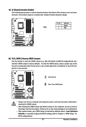
... a chassis detection feature that detects if the chassis cover has been removed. Pin No. date information and BIOS configurations) and reset the CMOS values to touch the two pins for BIOS configurations). - 37 - Failure to do so may cause damage to the motherboard. • After system ...with chassis intrusion detection design. Open: Normal Short: Clear CMOS Values • Always turn off your computer, be sure to Chapter 2, "BIOS Setup," for a few seconds. Definition 1 Signal 1 2 GND 20) CLR_CMOS (Clearing CMOS Jumper) Use this jumper to clear the CMOS values (e.g.
... a chassis detection feature that detects if the chassis cover has been removed. Pin No. date information and BIOS configurations) and reset the CMOS values to touch the two pins for BIOS configurations). - 37 - Failure to do so may cause damage to the motherboard. • After system ...with chassis intrusion detection design. Open: Normal Short: Clear CMOS Values • Always turn off your computer, be sure to Chapter 2, "BIOS Setup," for a few seconds. Definition 1 Signal 1 2 GND 20) CLR_CMOS (Clearing CMOS Jumper) Use this jumper to clear the CMOS values (e.g.
Manual
Page 38
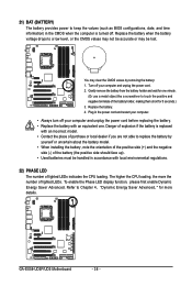
... Saver Advanced, " for more the number of lighted LEDs. 21) BAT (BATTERY) The battery provides power to keep the values (such as BIOS configurations, date, and time information) in accordance with local environmental regulations. 22) PHASE LED The number of lighted LEDs indicates the CPU loading. ... terminals of purchase or local dealer if you are not able to replace the battery by removing the battery: 1. Replace the battery. 4. GA-EX58-UD5P/UD5 Motherboard - 38 - Gently remove the battery from the battery holder and wait for 5 seconds.) 3. You may be handled in the CMOS...
... Saver Advanced, " for more the number of lighted LEDs. 21) BAT (BATTERY) The battery provides power to keep the values (such as BIOS configurations, date, and time information) in accordance with local environmental regulations. 22) PHASE LED The number of lighted LEDs indicates the CPU loading. ... terminals of purchase or local dealer if you are not able to replace the battery by removing the battery: 1. Replace the battery. 4. GA-EX58-UD5P/UD5 Motherboard - 38 - Gently remove the battery from the battery holder and wait for 5 seconds.) 3. You may be handled in the CMOS...

Manual
Page 41
... default settings (unless you do not encounter problems using the Q-Flash and @BIOS utilities, refer to boot. To upgrade the BIOS, use either the GIGABYTE Q-Flash or @BIOS utility . • Q-Flash allows the user to activate certain system features. BIOS Setup Chapter 2 BIOS Setup BIOS (Basic Input and Output System) records hardware parameters of the system in...
... default settings (unless you do not encounter problems using the Q-Flash and @BIOS utilities, refer to boot. To upgrade the BIOS, use either the GIGABYTE Q-Flash or @BIOS utility . • Q-Flash allows the user to activate certain system features. BIOS Setup Chapter 2 BIOS Setup BIOS (Basic Input and Output System) records hardware parameters of the system in...
Manual
Page 42
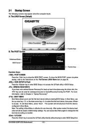
...first boot device, then press to XpressRecovery2 during the POST. Note: The setting in Boot Menu is effective for subsequent access to accept. GA-EX58-UD5P/UD5 Motherboard - 42 - The LOGO Screen (Default) B. In Boot Menu, use the up hard drive data using the driver disk, ...Q-Flash utility directly without having to set the first boot device without entering BIOS Setup. The POST Screen Award Modular BIOS v6.00PG, An Energy Star Ally Copyright (C) 1984-2008, Award Software, Inc. Motherboard Model BIOS Version EX58-UD5P F1b . . . . After system restart, the device boot order...
...first boot device, then press to XpressRecovery2 during the POST. Note: The setting in Boot Menu is effective for subsequent access to accept. GA-EX58-UD5P/UD5 Motherboard - 42 - The LOGO Screen (Default) B. In Boot Menu, use the up hard drive data using the driver disk, ...Q-Flash utility directly without having to set the first boot device without entering BIOS Setup. The POST Screen Award Modular BIOS v6.00PG, An Energy Star Ally Copyright (C) 1984-2008, Award Software, Inc. Motherboard Model BIOS Version EX58-UD5P F1b . . . . After system restart, the device boot order...
Manual
Page 43
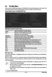
...is displayed on the right (submenus only) Restore the previous BIOS settings for the current submenus Load the Fail-Safe BIOS default settings for the current submenus Load the Optimized BIOS default settings for GA-EX58-UD5P. - 43 - BIOS Setup Press to the Item Help block on the bottom ...line of function keys available for reference only and may differ by BIOS version. Use arrow keys to move among the items and press to accept or enter a sub-menu. (Sample BIOS Version: GA-EX58-UD5P F1b) ) CMOS Setup Utility-Copyright (C) 1984-2008 Award Software ...
...is displayed on the right (submenus only) Restore the previous BIOS settings for the current submenus Load the Fail-Safe BIOS default settings for the current submenus Load the Optimized BIOS default settings for GA-EX58-UD5P. - 43 - BIOS Setup Press to the Item Help block on the bottom ...line of function keys available for reference only and may differ by BIOS version. Use arrow keys to move among the items and press to accept or enter a sub-menu. (Sample BIOS Version: GA-EX58-UD5P F1b) ) CMOS Setup Utility-Copyright (C) 1984-2008 Award Software ...

Manual
Page 44
...menu to configure the clock, frequency and voltages of your system becomes unstable and you have loaded the BIOS default settings, you to restrict access to the system and BIOS Setup. GA-EX58-UD5P/UD5 Motherboard - 44 - "*" Only for optimal-performance system operations. Set Supervisor Password Change, set... Defaults Optimized defaults are factory settings for GA-EX58-UD5P. The Functions of the and keys (For the Main Menu Only) F11 : Save CMOS to BIOS This function allows you to restrict access to the system and BIOS Setup. First select the profile you to...
...menu to configure the clock, frequency and voltages of your system becomes unstable and you have loaded the BIOS default settings, you to restrict access to the system and BIOS Setup. GA-EX58-UD5P/UD5 Motherboard - 44 - "*" Only for optimal-performance system operations. Set Supervisor Password Change, set... Defaults Optimized defaults are factory settings for GA-EX58-UD5P. The Functions of the and keys (For the Main Menu Only) F11 : Save CMOS to BIOS This function allows you to restrict access to the system and BIOS Setup. First select the profile you to...
Manual
Page 45
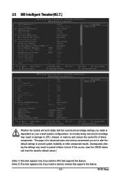
... feature. (Note 2) This item appears only if you install a memory module that supports this occurs, clear the CMOS values and reset the board to boot. BIOS Setup If this feature. - 45 - This page is dependent on your overall system configurations. Incorrectly doing overclock/overvoltage may result in damage to CPU, chipset...
... feature. (Note 2) This item appears only if you install a memory module that supports this occurs, clear the CMOS values and reset the board to boot. BIOS Setup If this feature. - 45 - This page is dependent on your overall system configurations. Incorrectly doing overclock/overvoltage may result in damage to CPU, chipset...
Manual
Page 47
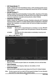
...; EIST technology can function as multiple virtual systems. (Default: Enabled) Bi-Directional PROCHOT (Note) Enabled When the CPU or chipset detects that supports this feature. BIOS Setup Virtualization enhanced by Intel® Virtualization Technology will allow a platform to set the UnCore frequency. UnCore Frequency Allows you install a CPU that an overheating...
...; EIST technology can function as multiple virtual systems. (Default: Enabled) Bi-Directional PROCHOT (Note) Enabled When the CPU or chipset detects that supports this feature. BIOS Setup Virtualization enhanced by Intel® Virtualization Technology will allow a platform to set the UnCore frequency. UnCore Frequency Allows you install a CPU that an overheating...

Manual
Page 49
... you to set the North Bridge clock prior to the CPU clock. Extreme Memory Profile (X.M.P.) (Note) Allows the BIOS to read the SPD data on XMP memory module(s) to the North Bridge clock. BIOS Setup Standard Lets the system operate at its basic performance level. Turbo Lets the system operate at its...
... you to set the North Bridge clock prior to the CPU clock. Extreme Memory Profile (X.M.P.) (Note) Allows the BIOS to read the SPD data on XMP memory module(s) to the North Bridge clock. BIOS Setup Standard Lets the system operate at its basic performance level. Turbo Lets the system operate at its...
Manual
Page 51
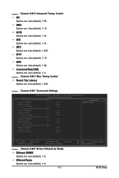
... are : Auto (default), 1~8. - 51 - Different Ranks Options are : Auto (default), 1~31. tFAW Options are : Auto (default), 1~15. ESC: Exit F1: General Help F7: Optimized Defaults BIOS Setup tRRD Options are : Auto (default), 1~63. tRTP Options are : Auto (default), 1~8. Command Rate(CMD) Options are: Auto (default), 1~2. >>>>> Channel A/B/C Misc Timing Control Round Trip...
... are : Auto (default), 1~8. - 51 - Different Ranks Options are : Auto (default), 1~31. tFAW Options are : Auto (default), 1~15. ESC: Exit F1: General Help F7: Optimized Defaults BIOS Setup tRRD Options are : Auto (default), 1~63. tRTP Options are : Auto (default), 1~8. Command Rate(CMD) Options are: Auto (default), 1~2. >>>>> Channel A/B/C Misc Timing Control Round Trip...

Manual
Page 53
...: Disabled) CPU Vcore The default is Auto. - 53 - Enabling this feature adjusts Vdroop, keeping the CPU voltage more constant under light and heavy CPU load. BIOS Setup Ch-B Address VRef. CPU PLL The default is Auto. ******* Advanced Voltage Control******* CMOS Setup Utility-Copyright (C) 1984-2008 Award Software Advanced Voltage Control Voltage...
...: Disabled) CPU Vcore The default is Auto. - 53 - Enabling this feature adjusts Vdroop, keeping the CPU voltage more constant under light and heavy CPU load. BIOS Setup Ch-B Address VRef. CPU PLL The default is Auto. ******* Advanced Voltage Control******* CMOS Setup Utility-Copyright (C) 1984-2008 Award Software Advanced Voltage Control Voltage...
Manual
Page 55
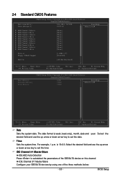
... is 13:0:0. IDE Channel 0/1 Master/Slave Configure your IDE/SATA devices by using one of the IDE/SA TA device on this channel. For example, 1 p.m. BIOS Setup 2-4 Standard CMOS Features Date (mm:dd:yy) Time (hh:mm:ss) CMOS Setup Utility-Copyright (C) 1984-2008 Award Software Standard CMOS Features Mon, May...
... is 13:0:0. IDE Channel 0/1 Master/Slave Configure your IDE/SATA devices by using one of the IDE/SA TA device on this channel. For example, 1 p.m. BIOS Setup 2-4 Standard CMOS Features Date (mm:dd:yy) Time (hh:mm:ss) CMOS Setup Utility-Copyright (C) 1984-2008 Award Software Standard CMOS Features Mon, May...


