Manual
Page 3
... TECHNOLOGY CO., LTD as the exclu- For product-related information, check on our website at: http://www.gigabyte.com.tw Identifying Your Motherboard Revision The revision number on your motherboard revision before updating motherboard BIOS, drivers, or when looking for technical information. All rights reserved. Documentation Classifications In order to the specifications...
... TECHNOLOGY CO., LTD as the exclu- For product-related information, check on our website at: http://www.gigabyte.com.tw Identifying Your Motherboard Revision The revision number on your motherboard revision before updating motherboard BIOS, drivers, or when looking for technical information. All rights reserved. Documentation Classifications In order to the specifications...
Manual
Page 4
Table of Contents Box Contents ...6 OptionalItems ...6 GA-EX38-DS4 Motherboard Layout 7 Block Diagram ...8 Chapter 1 Hardware Installation 9 1-1 Installation Precautions 9 1-2 Product Specifications 10 1-3 Installing the CPU and CPU Cooler 13 ... Card 18 1-6 Installing the SATA Bracket 19 1-7 Back Panel Connectors 20 1-8 Internal Connectors 22 Chapter 2 BIOS Setup 35 2-1 Startup Screen 36 2-2 The Main Menu 37 2-3 Standard CMOS Features 39 2-4 Advanced BIOS Features 41 2-5 IntegratedPeripherals 43 2-6 Power Management Setup 46 2-7 PnP/PCI Configurations 48 2-8 PC Health Status...
Table of Contents Box Contents ...6 OptionalItems ...6 GA-EX38-DS4 Motherboard Layout 7 Block Diagram ...8 Chapter 1 Hardware Installation 9 1-1 Installation Precautions 9 1-2 Product Specifications 10 1-3 Installing the CPU and CPU Cooler 13 ... Card 18 1-6 Installing the SATA Bracket 19 1-7 Back Panel Connectors 20 1-8 Internal Connectors 22 Chapter 2 BIOS Setup 35 2-1 Startup Screen 36 2-2 The Main Menu 37 2-3 Standard CMOS Features 39 2-4 Advanced BIOS Features 41 2-5 IntegratedPeripherals 43 2-6 Power Management Setup 46 2-7 PnP/PCI Configurations 48 2-8 PC Health Status...

Manual
Page 5
... 60 3-3 Driver CD Information 60 3-4 Hardware Information 61 3-5 Contact Us ...61 Chapter 4 Unique Features 63 4-1 Xpress Recovery2 63 4-2 BIOS Update Utilities 68 4-2-1 Updating the BIOS with the Q-Flash Utility 68 4-2-2 Updating the BIOS with the @BIOS Utility 71 4-3 EasyTune 5 Pro 73 4-4 Dynamic Energy Saver 74 4-5 Windows Vista ReadyBoost 76 Chapter 5 Appendix ...77 5-1 Configuring SATA...
... 60 3-3 Driver CD Information 60 3-4 Hardware Information 61 3-5 Contact Us ...61 Chapter 4 Unique Features 63 4-1 Xpress Recovery2 63 4-2 BIOS Update Utilities 68 4-2-1 Updating the BIOS with the Q-Flash Utility 68 4-2-2 Updating the BIOS with the @BIOS Utility 71 4-3 EasyTune 5 Pro 73 4-4 Dynamic Energy Saver 74 4-5 Windows Vista ReadyBoost 76 Chapter 5 Appendix ...77 5-1 Configuring SATA...

Manual
Page 8
... 8111B x1 x1 x1 x1 x1 PCI Express Bus ATA-133/100/66/ 33 IDE Channel GIGABYTE SATA2 Intel® X38 Intel® ICH9R Dual Channel Memory MCH CLK (400/333/266/200 MHz) Dual BIOS 6 SATA 3Gb/s 12 USB Ports PCI Bus TSB43AB23 3 IEEE 1394a CODEC IT8718 Floppy LPT Port COM...
... 8111B x1 x1 x1 x1 x1 PCI Express Bus ATA-133/100/66/ 33 IDE Channel GIGABYTE SATA2 Intel® X38 Intel® ICH9R Dual Channel Memory MCH CLK (400/333/266/200 MHz) Dual BIOS 6 SATA 3Gb/s 12 USB Ports PCI Bus TSB43AB23 3 IEEE 1394a CODEC IT8718 Floppy LPT Port COM...
Manual
Page 12
... Š Support for Dynamic Energy Saver Š Norton Internet Security (OEM version) Š Voltage adjustments in BIOS Setup (CPU/DDR2/PCIe/FSB/(G)MCH) allow you to 0.35V with 1 MHz increment - Increase CPU voltage (Note 4) - GA-EX38-DS4 Motherboard - 12 - BIOS Unique Features Bundled Software Overclocking Operating System Form Factor Š 2 x 8 Mbit flash Š Use of...
... Š Support for Dynamic Energy Saver Š Norton Internet Security (OEM version) Š Voltage adjustments in BIOS Setup (CPU/DDR2/PCIe/FSB/(G)MCH) allow you to 0.35V with 1 MHz increment - Increase CPU voltage (Note 4) - GA-EX38-DS4 Motherboard - 12 - BIOS Unique Features Bundled Software Overclocking Operating System Form Factor Š 2 x 8 Mbit flash Š Use of...
Manual
Page 16
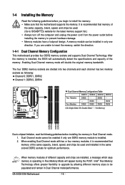
...the POST. 1-4 Installing the Memory Read the following guidelines before you are installed, a message which says memory is installed, the BIOS will double the original memory bandwidth. After the memory is operating in Dual Channel mode/performance. DS/SS - - Enabling Dual Channel...DS/SS DDRII4 - Intel® Flex Memory Technology offers greater flexibility to upgrade by allowing different memory sizes to GIGABYTE's website for optimum performance. GA-EX38-DS4 Motherboard - 16 - The four DDR2 memory sockets are divided into two channels and each channel has two memory...
...the POST. 1-4 Installing the Memory Read the following guidelines before you are installed, a message which says memory is installed, the BIOS will double the original memory bandwidth. After the memory is operating in Dual Channel mode/performance. DS/SS - - Enabling Dual Channel...DS/SS DDRII4 - Intel® Flex Memory Technology offers greater flexibility to upgrade by allowing different memory sizes to GIGABYTE's website for optimum performance. GA-EX38-DS4 Motherboard - 16 - The four DDR2 memory sockets are divided into two channels and each channel has two memory...
Manual
Page 18
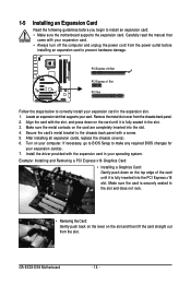
... motherboard supports the expansion card. Align the card with the expansion card in the expansion slot. 1. After installing all expansion cards, replace the chassis cover(s). 6. GA-EX38-DS4 Motherboard - 18 - Make sure the card is securely seated in the slot. 3. Install the driver provided with the slot, and press down on your expansion... an expansion card to prevent hardware damage. PCI Express x16 Slot PCI Express x1 Slot PCI Slot Follow the steps below to make any required BIOS changes for your expansion card in your card. If necessary, go to...
... motherboard supports the expansion card. Align the card with the expansion card in the expansion slot. 1. After installing all expansion cards, replace the chassis cover(s). 6. GA-EX38-DS4 Motherboard - 18 - Make sure the card is securely seated in the slot. 3. Install the driver provided with the slot, and press down on your expansion... an expansion card to prevent hardware damage. PCI Express x16 Slot PCI Express x1 Slot PCI Slot Follow the steps below to make any required BIOS changes for your expansion card in your card. If necessary, go to...
Manual
Page 27
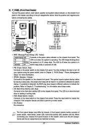
...LED Connects to the power status indicator on the chassis front panel. The S0 On LED is on when the system is detected, the BIOS may issue beeps in different patterns to indicate the problem. The system reports system startup status by chassis. Press the reset switch to ... (Reset Switch, Green): Connects to the reset switch on the chassis front panel. When connecting your system using the power switch (refer to Chapter 2, "BIOS Setup," "Power Management Setup," for information about beep codes. • HD (Hard Drive Activity LED, Blue) Connects to the speaker on the chassis front...
...LED Connects to the power status indicator on the chassis front panel. The S0 On LED is on when the system is detected, the BIOS may issue beeps in different patterns to indicate the problem. The system reports system startup status by chassis. Press the reset switch to ... (Reset Switch, Green): Connects to the reset switch on the chassis front panel. When connecting your system using the power switch (refer to Chapter 2, "BIOS Setup," "Power Management Setup," for information about beep codes. • HD (Hard Drive Activity LED, Blue) Connects to the speaker on the chassis front...
Manual
Page 33
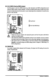
...so may cause damage to the motherboard. • After system restart, go to BIOS Setup to load factory defaults (select Load Optimized Defaults) or manually configure the BIOS settings (refer to touch the two pins for BIOS configurations). 23) PHASE LED The number of lighted LEDs. - 33 - Hardware ...Open: Normal Short: Clear CMOS Values • Always turn off your computer and unplug the power cord from the jumper. date information and BIOS configurations) and reset the CMOS values to clear the CMOS values (e.g. The higher the CPU loading, the more the number of lighted LEDs...
...so may cause damage to the motherboard. • After system restart, go to BIOS Setup to load factory defaults (select Load Optimized Defaults) or manually configure the BIOS settings (refer to touch the two pins for BIOS configurations). 23) PHASE LED The number of lighted LEDs. - 33 - Hardware ...Open: Normal Short: Clear CMOS Values • Always turn off your computer and unplug the power cord from the jumper. date information and BIOS configurations) and reset the CMOS values to clear the CMOS values (e.g. The higher the CPU loading, the more the number of lighted LEDs...
Manual
Page 34
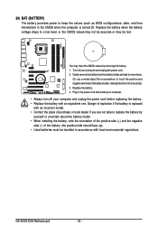
... object like a screwdriver to keep the values (such as BIOS configurations, date, and time information) in the CMOS when the computer is replaced with local environmental regulations. Replace the battery when the battery voltage drops to replace the battery by removing the battery: 1. GA-EX38-DS4 Motherboard - 34 - 24) BAT (BATTERY) The battery provides...
... object like a screwdriver to keep the values (such as BIOS configurations, date, and time information) in the CMOS when the computer is replaced with local environmental regulations. Replace the battery when the battery voltage drops to replace the battery by removing the battery: 1. GA-EX38-DS4 Motherboard - 34 - 24) BAT (BATTERY) The battery provides...

Manual
Page 35
... on . Refer to prevent system instability or other unexpected results. To upgrade the BIOS, use either the GIGABYTE Q-Flash or @BIOS utility. • Q-Flash allows the user to quickly and easily upgrade or back up BIOS without entering the operating system. • @BIOS is a Windows-based utility that you not alter the default settings (unless...
... on . Refer to prevent system instability or other unexpected results. To upgrade the BIOS, use either the GIGABYTE Q-Flash or @BIOS utility. • Q-Flash allows the user to quickly and easily upgrade or back up BIOS without entering the operating system. • @BIOS is a Windows-based utility that you not alter the default settings (unless...

Manual
Page 36
... setting as needed. : Q-Flash Press the key to access the Q-Flash utility directly without entering BIOS Setup. The system will still be used for one time only. EX38-DS4 F1a . . . . : BIOS Setup : XpressRecovery2 : Boot Menu : Qflash 01/02/2008-X38-ICH9-6A89OG0WC-00 Function Keys Function... be based on page 42. : BIOS Setup/Q-Flash Press the key to enter BIOS Setup or to access the Q-Flash utility in BIOS Setup. : Xpress Recovery2 If you to show the BIOS POST screen at system startup, refer to enter BIOS Setup first. GA-EX38-DS4 Motherboard - 36 - Note: The ...
... setting as needed. : Q-Flash Press the key to access the Q-Flash utility directly without entering BIOS Setup. The system will still be used for one time only. EX38-DS4 F1a . . . . : BIOS Setup : XpressRecovery2 : Boot Menu : Qflash 01/02/2008-X38-ICH9-6A89OG0WC-00 Function Keys Function... be based on page 42. : BIOS Setup/Q-Flash Press the key to enter BIOS Setup or to access the Q-Flash utility in BIOS Setup. : Xpress Recovery2 If you to show the BIOS POST screen at system startup, refer to enter BIOS Setup first. GA-EX38-DS4 Motherboard - 36 - Note: The ...

Manual
Page 37
...to the Item Help block on the right (submenus only) Restore the previous BIOS settings for the current submenus Load the Fail-Safe BIOS default settings for the current submenus Load the Optimized BIOS default settings for the current submenus Access the Q-Flash utility Display system information Save...Exit Setup Exit Without Saving ESC: Quit F8: Q-Flash KLJI: Select Item F10: Save & Exit Setup F11: Save CMOS to BIOS F12: Load CMOS from BIOS Main Menu Help The onscreen description of a highlighted setup option is displayed on the right side of the submenu. • If you...
...to the Item Help block on the right (submenus only) Restore the previous BIOS settings for the current submenus Load the Fail-Safe BIOS default settings for the current submenus Load the Optimized BIOS default settings for the current submenus Access the Q-Flash utility Display system information Save...Exit Setup Exit Without Saving ESC: Quit F8: Q-Flash KLJI: Select Item F10: Save & Exit Setup F11: Save CMOS to BIOS F12: Load CMOS from BIOS Main Menu Help The onscreen description of a highlighted setup option is displayed on the right side of the submenu. • If you...

Manual
Page 38
... menu to configure all peripheral devices, such as IDE, SATA, USB, integrated audio, and integrated LAN, etc. „ Power Management Setup Use this task.) GA-EX38-DS4 Motherboard - 38 - An user password only allows you to view the BIOS settings but not to make changes in effect. Pressing to the confirmation message will exit...
... menu to configure all peripheral devices, such as IDE, SATA, USB, integrated audio, and integrated LAN, etc. „ Power Management Setup Use this task.) GA-EX38-DS4 Motherboard - 38 - An user password only allows you to view the BIOS settings but not to make changes in effect. Pressing to the confirmation message will exit...

Manual
Page 39
... the date. Select the desired field and use the up arrow or down arrow key to autodetect the parameters of the three methods below: - 39 - BIOS Setup Time Sets the system time. For example, 1 p.m. IDE Channel 0/1 Master/Slave Configure your IDE/SATA devices by using one of the IDE/SATA device...
... the date. Select the desired field and use the up arrow or down arrow key to autodetect the parameters of the three methods below: - 39 - BIOS Setup Time Sets the system time. For example, 1 p.m. IDE Channel 0/1 Master/Slave Configure your IDE/SATA devices by using one of the IDE/SATA device...

Manual
Page 40
...The total amount of floppy disk drive installed in your hard drive specifications. Extended IDE Drive Configure your IDE/SATA devices by the BIOS POST. If you to determine whether the system will stop for faster system startup. Landing Zone Landing zone. Sector Number of ... non-fatal error the system boot will stop for a keyboard or a floppy disk drive error but stop for all other errors. GA-EX38-DS4 Motherboard - 40 - • Auto Lets BIOS automatically detect IDE/SATA devices during the POST. (Default) • None If no IDE/SATA devices are : None, 360K/5.25...
...The total amount of floppy disk drive installed in your hard drive specifications. Extended IDE Drive Configure your IDE/SATA devices by the BIOS POST. If you to determine whether the system will stop for faster system startup. Landing Zone Landing zone. Sector Number of ... non-fatal error the system boot will stop for a keyboard or a floppy disk drive error but stop for all other errors. GA-EX38-DS4 Motherboard - 40 - • Auto Lets BIOS automatically detect IDE/SATA devices during the POST. (Default) • None If no IDE/SATA devices are : None, 360K/5.25...

Manual
Page 41
Password Check Specifies whether a password is required every time the system boots, or only when you install a CPU that supports this feature. BIOS Setup Use the up or down arrow key to select a hard drive, then press the plus key (or ) or the minus key (or ) to exit ...this item, set the password(s) under the Set Supervisor/User Password item in the BIOS Main Menu. Press to move it up or down on the list. Options are: Floppy, LS120, Hard Disk, CDROM, ZIP, USB-FDD, USB-ZIP, USB...
Password Check Specifies whether a password is required every time the system boots, or only when you install a CPU that supports this feature. BIOS Setup Use the up or down arrow key to select a hard drive, then press the plus key (or ) or the minus key (or ) to exit ...this item, set the password(s) under the Set Supervisor/User Password item in the BIOS Main Menu. Press to move it up or down on the list. Options are: Floppy, LS120, Hard Disk, CDROM, ZIP, USB-FDD, USB-ZIP, USB...

Manual
Page 43
... the integrated USB 2.0 controller. (Default: Enabled) USB Keyboard Support Allows USB keyboard to operate in Legacy IDE mode. RAID Enables RAID for the SATA controllers. BIOS Setup In Legacy mode the SATA controllers use dedicated IRQs that support Native mode, e.g. Windows XP/2000. Set this option to Disabled if you wish...
... the integrated USB 2.0 controller. (Default: Enabled) USB Keyboard Support Allows USB keyboard to operate in Legacy IDE mode. RAID Enables RAID for the SATA controllers. BIOS Setup In Legacy mode the SATA controllers use dedicated IRQs that support Native mode, e.g. Windows XP/2000. Set this option to Disabled if you wish...

Manual
Page 45
... environment, so their Status fields will show Short and then length shown will show Open, and the length shown is activated. BIOS Setup Link Detected --> 100Mbps Cable Length= 30m Link Detected Cable Length Displays transmission speed Displays the approximate length of wires, the...(LPT) and specifies its base I /O address and corresponding interrupt. it will appear: Start detecting at a speed of 10/100 Mbps in the GIGABYTE SATA2 chip. (Default: Enabled) Onboard Serial Port 1 Enables or disables the first serial port and specifies its base I /O address and corresponding interrupt...
... environment, so their Status fields will show Short and then length shown will show Open, and the length shown is activated. BIOS Setup Link Detected --> 100Mbps Cable Length= 30m Link Detected Cable Length Displays transmission speed Displays the approximate length of wires, the...(LPT) and specifies its base I /O address and corresponding interrupt. it will appear: Start detecting at a speed of 10/100 Mbps in the GIGABYTE SATA2 chip. (Default: Enabled) Onboard Serial Port 1 Enables or disables the first serial port and specifies its base I /O address and corresponding interrupt...

Manual
Page 47
... to accept. Soft-Off The system stays off upon the return of the AC power. (Default) Full-On Memory The system is set to Password. BIOS Setup HPET Support (Note) Enables or disables High Precision Event Timer (HPET) for Windows® Vista® operating system. (Default: Enabled) HPET Mode (Note) Allows...
... to accept. Soft-Off The system stays off upon the return of the AC power. (Default) Full-On Memory The system is set to Password. BIOS Setup HPET Support (Note) Enables or disables High Precision Event Timer (HPET) for Windows® Vista® operating system. (Default: Enabled) HPET Mode (Note) Allows...


