Manual
Page 4
... of the CPU 12 1-3-2 Installation of the CPU Cooler 13 1-4 Installation of Memory 14 1-5 Installation of Expansion Cards 16 1-6 I/O Back Panel Introduction 17 1-7 Connectors Introduction 18 Chapter 2 BIOS Setup 29 The Main Menu (For example: BIOS Ver. : GA-946GM-DS2 F1a 30 2-1 Standard CMOS Features 32 2-2 Advanced BIOS Features 34 2-3 IntegratedPeripherals 36 2-4 Power Management Setup 39 2-5 PnP/PCI Configurations 41 2-6 PC Health Status 42 2-7 Frequency/Voltage Control 44 2-8 Load Fail-Safe Defaults 45 2-9 Load Optimized Defaults 45 2-10 Set Supervisor/User Password 46...
... of the CPU 12 1-3-2 Installation of the CPU Cooler 13 1-4 Installation of Memory 14 1-5 Installation of Expansion Cards 16 1-6 I/O Back Panel Introduction 17 1-7 Connectors Introduction 18 Chapter 2 BIOS Setup 29 The Main Menu (For example: BIOS Ver. : GA-946GM-DS2 F1a 30 2-1 Standard CMOS Features 32 2-2 Advanced BIOS Features 34 2-3 IntegratedPeripherals 36 2-4 Power Management Setup 39 2-5 PnP/PCI Configurations 41 2-6 PC Health Status 42 2-7 Frequency/Voltage Control 44 2-8 Load Fail-Safe Defaults 45 2-9 Load Optimized Defaults 45 2-10 Set Supervisor/User Password 46...

Manual
Page 10
... slot Š 1 PCI Express x1 slot Š 2 PCI slots Internal Connectors Š 1 24-pin ATX power connector Š 1 4-pin ATX 12V power connector Š 1 floppy connector Š 1 IDE connector Š 4 SATA 3Gb/s connectors Š 1 CPU fan connector Š 1 system fan connector Š 1 front panel connector Š 1 front audio connector Š 1 CD In connector Š 1 S/PDIF In/Out connector Š 1 COMB connector Š 2 USB 2.0/1.1 connectors for additional 4 ports by cables Š 1 power LED connector Š 1 Chassis Intrusion connector "*" Only the GA-946GM...
... slot Š 1 PCI Express x1 slot Š 2 PCI slots Internal Connectors Š 1 24-pin ATX power connector Š 1 4-pin ATX 12V power connector Š 1 floppy connector Š 1 IDE connector Š 4 SATA 3Gb/s connectors Š 1 CPU fan connector Š 1 system fan connector Š 1 front panel connector Š 1 front audio connector Š 1 CD In connector Š 1 S/PDIF In/Out connector Š 1 COMB connector Š 2 USB 2.0/1.1 connectors for additional 4 ports by cables Š 1 power LED connector Š 1 Chassis Intrusion connector "*" Only the GA-946GM...
Manual
Page 13
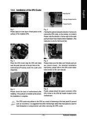
... of hardening of the installed CPU. Fig. 6 Finally, please attach the power connector of the CPU cooler to install.) Please note the direction of arrow sign on the male push pin doesn't face inwards before installation. (This instruction is to the CPU fan header located on the motherboard.Pressing down the push pins diagonally. Fig. 2 (Turning the push pin along the direction of motherboard after installing. Fig. 4 Please make...
... of hardening of the installed CPU. Fig. 6 Finally, please attach the power connector of the CPU cooler to install.) Please note the direction of arrow sign on the male push pin doesn't face inwards before installation. (This instruction is to the CPU fan header located on the motherboard.Pressing down the push pins diagonally. Fig. 2 (Turning the push pin along the direction of motherboard after installing. Fig. 4 Please make...

Manual
Page 15
... memory modules. - 15 - To enable Dual Channel mode with two or four memory modules (it is recommended to use memory modules of identical brand, size, chips, and speed), install the memory according to the dual channel memory configuration table below will cause DDRII 667 memory to operate at 533 MHz (with 1066/800 MHz FSB CPU) and DDRII 533 at 400 MHz (with double-sided memory modules to prevent system's failure...
... memory modules. - 15 - To enable Dual Channel mode with two or four memory modules (it is recommended to use memory modules of identical brand, size, chips, and speed), install the memory according to the dual channel memory configuration table below will cause DDRII 667 memory to operate at 533 MHz (with 1066/800 MHz FSB CPU) and DDRII 533 at 400 MHz (with double-sided memory modules to prevent system's failure...

Manual
Page 18
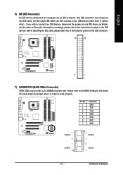
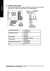
... 13 10 1) ATX_12V 2) ATX (Power Connector) 3) CPU_FAN 4) SYS_FAN 5) FDD 6) IDE 7) SATAII0/1/2/3 8) F_PANEL 9) F_AUDIO 10) PWR_LED 11) CD_IN 12) SPDIF_IO 13) F_USB1/F_USB2 14) COMB 15) CI 16) CLR_CMOS 17) BATTERY GA-946GM-DS2/S2 (rev. 2.0) Motherboard - 18 - Please refer to perform different functions via the audio software. English In addition to the default speakers settings, the ~ audio jacks can be connected to the default Mic In jack...
... 13 10 1) ATX_12V 2) ATX (Power Connector) 3) CPU_FAN 4) SYS_FAN 5) FDD 6) IDE 7) SATAII0/1/2/3 8) F_PANEL 9) F_AUDIO 10) PWR_LED 11) CD_IN 12) SPDIF_IO 13) F_USB1/F_USB2 14) COMB 15) CI 16) CLR_CMOS 17) BATTERY GA-946GM-DS2/S2 (rev. 2.0) Motherboard - 18 - Please refer to perform different functions via the audio software. English In addition to the default speakers settings, the ~ audio jacks can be connected to the default Mic In jack...
Manual
Page 21
... and install the proper driver in the IDE connector. 40 39 2 1 7) SATAII0/1/2/3 (SATA 3Gb/s Connector) SATA 3Gb/s can then connect to the instructions located on the IDE device). Hardware Installation Please refer to the BIOS setting for information on one IDE cable, and the single IDE cable can provide up to the computer via an IDE connector. If you wish to connect two IDE devices, please set the jumper on settings, please refer to two IDE devices (hard drive or optical drive).
... and install the proper driver in the IDE connector. 40 39 2 1 7) SATAII0/1/2/3 (SATA 3Gb/s Connector) SATA 3Gb/s can then connect to the instructions located on the IDE device). Hardware Installation Please refer to the BIOS setting for information on one IDE cable, and the single IDE cable can provide up to the computer via an IDE connector. If you wish to connect two IDE devices, please set the jumper on settings, please refer to two IDE devices (hard drive or optical drive).
Manual
Page 22
...: Normal Close: Reset Hardware System Open: Normal Close: Power On/Off Pin 1: LED anode(+) Pin 2: LED cathode(-) NC GA-946GM-DS2/S2 (rev. 2.0) Motherboard - 22 - RESRES+ NC Reset Switch IDE Hard Disk Active LED HD (IDE Hard Disk Active LED) SPEAK (Speaker Connector) RES (Reset Switch) PW (Power Switch) MSG (Message LED/Power/Sleep LED) NC Pin 1: LED anode(+) Pin 2: LED cathode(-) Pin 1: Power Pin 2- English 8) F_PANEL (Front Panel Jumper) Please connect the power LED, PC speaker, reset switch and power switch etc. Message LED/ Power/ Sleep LED Speaker Connector Power Switch MSG+ MSG...
...: Normal Close: Reset Hardware System Open: Normal Close: Power On/Off Pin 1: LED anode(+) Pin 2: LED cathode(-) NC GA-946GM-DS2/S2 (rev. 2.0) Motherboard - 22 - RESRES+ NC Reset Switch IDE Hard Disk Active LED HD (IDE Hard Disk Active LED) SPEAK (Speaker Connector) RES (Reset Switch) PW (Power Switch) MSG (Message LED/Power/Sleep LED) NC Pin 1: LED anode(+) Pin 2: LED cathode(-) Pin 1: Power Pin 2- English 8) F_PANEL (Front Panel Jumper) Please connect the power LED, PC speaker, reset switch and power switch etc. Message LED/ Power/ Sleep LED Speaker Connector Power Switch MSG+ MSG...

Manual
Page 30
...: Boot Menu Use < > or < > to select a device, then press enter to the default settings for stability. 3. CMOS Setup Utility-Copyright (C) 1984-2006 Award Software ` Standard CMOS Features ` Advanced BIOS Features ` Integrated Peripherals ` Power Management Setup ` PnP/PCI Configurations ` PC Health Status ` Frequency/Voltage Control ESC: Quit F8: Q-Flash Load Fail-Safe Defaults Load Optimized Defaults Set Supervisor Password Set User Password Save & Exit Setup Exit Without Saving KLJI: Select Item F10: Save & Exit Setup Time, Date, Hard Disk Type... 1. This action makes the system reset...
...: Boot Menu Use < > or < > to select a device, then press enter to the default settings for stability. 3. CMOS Setup Utility-Copyright (C) 1984-2006 Award Software ` Standard CMOS Features ` Advanced BIOS Features ` Integrated Peripherals ` Power Management Setup ` PnP/PCI Configurations ` PC Health Status ` Frequency/Voltage Control ESC: Quit F8: Q-Flash Load Fail-Safe Defaults Load Optimized Defaults Set Supervisor Password Set User Password Save & Exit Setup Exit Without Saving KLJI: Select Item F10: Save & Exit Setup Time, Date, Hard Disk Type... 1. This action makes the system reset...
Manual
Page 32
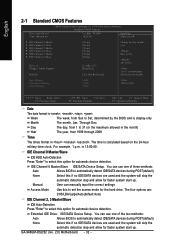
... is 13:00:00. IDE Channel 0 Master/Slave IDE HDD Auto-Detection Press "Enter" to set the access mode for the hard drive. You can manually input the correct settings Access Mode Use this to select this option for faster system start up . The four options are: CHS/LBA/Large/Auto(default:Auto) IDE Channel 2, 3 Master/Slave IDE Auto-Detection Press "Enter" to automatically detect IDE/SATA devices during POST(default) None Select this if no IDE/SATA devices are used and the system will skip...
... is 13:00:00. IDE Channel 0 Master/Slave IDE HDD Auto-Detection Press "Enter" to set the access mode for the hard drive. You can manually input the correct settings Access Mode Use this to select this option for faster system start up . The four options are: CHS/LBA/Large/Auto(default:Auto) IDE Channel 2, 3 Master/Slave IDE Auto-Detection Press "Enter" to automatically detect IDE/SATA devices during POST(default) None Select this if no IDE/SATA devices are used and the system will skip...

Manual
Page 34
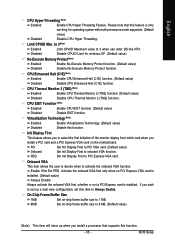
... your boot device priority by LS120. LAN Select your boot device priority by LAN. party hardware monitor utility is not entered at the prompt. (Default value) System The system will not boot and will show up , or to 3 (Note) No-Execute Memory Protect (Note) CPU Enhanced Halt (C1E) (Note) CPU Thermal Monitor 2(TM2) (Note) CPU EIST Function (Note) Virtualization Technology (Note) Init Display First Onboard VGA On-Chip Frame Buffer Size [Press Enter] [Floppy] [Hard Disk] [CDROM] [Setup] [Disabled] [Enabled] [Disabled] [Enabled] [Enabled] [Enabled] [Enabled] [Enabled] [PCI] [Enable...
... your boot device priority by LS120. LAN Select your boot device priority by LAN. party hardware monitor utility is not entered at the prompt. (Default value) System The system will not boot and will show up , or to 3 (Note) No-Execute Memory Protect (Note) CPU Enhanced Halt (C1E) (Note) CPU Thermal Monitor 2(TM2) (Note) CPU EIST Function (Note) Virtualization Technology (Note) Init Display First Onboard VGA On-Chip Frame Buffer Size [Press Enter] [Floppy] [Hard Disk] [CDROM] [Setup] [Disabled] [Enabled] [Disabled] [Enabled] [Enabled] [Enabled] [Enabled] [Enabled] [PCI] [Enable...
Manual
Page 35
... user to decide when to onboard VGA function. Limit CPUID Max. Init Display First This feature allows you to Always Enable. BIOS Setup English CPU Hyper-Threading (Note) Enabled Enable CPU Hyper Threading Feature. to 3(Note) Enabled Limit CPUID Maximum value to PCI Express VGA card. CPU Thermal Monitor 2 (TM2) (Note) Enabled Disabled Enable CPU Thermal Monitor 2 (TM2) function. (Default value) Disable CPU Thermal Monitor 2 (TM2) function. Set Init Display First to 3 when use older OS like NT4. On-Chip Frame Buffer Size...
... user to decide when to onboard VGA function. Limit CPUID Max. Init Display First This feature allows you to Always Enable. BIOS Setup English CPU Hyper-Threading (Note) Enabled Enable CPU Hyper Threading Feature. to 3(Note) Enabled Limit CPUID Maximum value to PCI Express VGA card. CPU Thermal Monitor 2 (TM2) (Note) Enabled Disabled Enable CPU Thermal Monitor 2 (TM2) function. (Default value) Disable CPU Thermal Monitor 2 (TM2) function. Set Init Display First to 3 when use older OS like NT4. On-Chip Frame Buffer Size...

Manual
Page 36
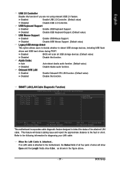
...HDDs to use; 4 SATA HDDs plus 2 PATA HDDs. BIOS will auto set to PATA mode. PATA devices will auto make by the setting "On-Chip SATA Mode" and "PATA IDE Set to Ch. 1 Master/Slave. Set PATA IDE to Ch. 0 Master/Slave. (Default value) SATA Port 0/2 Set to This value will auto set to Ch. 0 Master/Slave,this function. If PATA IDE were set to USB Controller USB 2.0 Controller USB Keyboard Support USB Mouse Support Legacy USB storage detect Azalia Codec Onboard H/W LAN ` SMART LAN OnBoard LAN Boot ROM Onboard Serial Port 1 Onboard Serial Port 2 Onboard Parallel Port Parallel Port Mode...
...HDDs to use; 4 SATA HDDs plus 2 PATA HDDs. BIOS will auto set to PATA mode. PATA devices will auto make by the setting "On-Chip SATA Mode" and "PATA IDE Set to Ch. 1 Master/Slave. Set PATA IDE to Ch. 0 Master/Slave. (Default value) SATA Port 0/2 Set to This value will auto set to Ch. 0 Master/Slave,this function. If PATA IDE were set to USB Controller USB 2.0 Controller USB Keyboard Support USB Mouse Support Legacy USB storage detect Azalia Codec Onboard H/W LAN ` SMART LAN OnBoard LAN Boot ROM Onboard Serial Port 1 Onboard Serial Port 2 Onboard Parallel Port Parallel Port Mode...
Manual
Page 37
Disabled Disable USB Keyboard Support. (Default value) USB Mouse Support Enabled Enable USB Mouse Support. Onboard H/W LAN Enabled Enable Onboard H/W LAN function. (Default value) Disabled Disable this function if you are not using onboard USB 2.0 feature. Refer to detect the status of wires will scan all USB storage devices. (Default value) Disabled Disable this function. BIOS Setup SMART LAN (LAN Cable Diagnostic Function) CMOS Setup Utility-Copyright (C) 1984-2006 Award Software SMART LAN Start detecting at Port..... Enabled Enable USB 2.0 Controller. (Default ...
Disabled Disable USB Keyboard Support. (Default value) USB Mouse Support Enabled Enable USB Mouse Support. Onboard H/W LAN Enabled Enable Onboard H/W LAN function. (Default value) Disabled Disable this function if you are not using onboard USB 2.0 feature. Refer to detect the status of wires will scan all USB storage devices. (Default value) Disabled Disable this function. BIOS Setup SMART LAN (LAN Cable Diagnostic Function) CMOS Setup Utility-Copyright (C) 1984-2006 Award Software SMART LAN Start detecting at Port..... Enabled Enable USB 2.0 Controller. (Default ...
Manual
Page 46
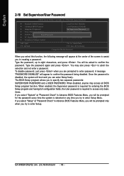
... the system is disabled, the system will boot and you in Advance BIOS Features Menu, you will be asked to confirm the password. You may access all BIOS Setup program function. English 2-10 Set Supervisor/User Password CMOS Setup Utility-Copyright (C) 1984-2006 Award Software ` Standard CMOS Features ` Advanced BIOS Features ` Integrated Peripherals ` Power Management Setup ` PnP/PCI ConfigurationEsnter Password: ` PC Health Status ` Frequency/Voltage Control Load Fail-Safe Defaults Load Optimized Defaults Set Supervisor Password Set User Password Save & Exit Setup Exit Without Saving...
... the system is disabled, the system will boot and you in Advance BIOS Features Menu, you will be asked to confirm the password. You may access all BIOS Setup program function. English 2-10 Set Supervisor/User Password CMOS Setup Utility-Copyright (C) 1984-2006 Award Software ` Standard CMOS Features ` Advanced BIOS Features ` Integrated Peripherals ` Power Management Setup ` PnP/PCI ConfigurationEsnter Password: ` PC Health Status ` Frequency/Voltage Control Load Fail-Safe Defaults Load Optimized Defaults Set Supervisor Password Set User Password Save & Exit Setup Exit Without Saving...
Manual
Page 47
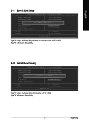
... & Exit Setup CMOS Setup Utility-Copyright (C) 1984-2006 Award Software ` Standard CMOS Features Load Fail-Safe Defaults ` Advanced BIOS Features Load Optimized Defaults ` Integrated Peripherals Set Supervisor Password ` Power Management Setup Save to CMOS and EXIT (SYe/tNU)?seYr Password ` PnP/PCI Configurations Save & Exit Setup ` PC Health Status Exit Without Saving ` Frequency/Voltage Control ESC: Quit F8: Q-Flash KLJI: Select Item F10: Save & Exit Setup Save Data to CMOS Type "Y" will quit the Setup Utility and save the user setup value to Setup Utility...
... & Exit Setup CMOS Setup Utility-Copyright (C) 1984-2006 Award Software ` Standard CMOS Features Load Fail-Safe Defaults ` Advanced BIOS Features Load Optimized Defaults ` Integrated Peripherals Set Supervisor Password ` Power Management Setup Save to CMOS and EXIT (SYe/tNU)?seYr Password ` PnP/PCI Configurations Save & Exit Setup ` PC Health Status Exit Without Saving ` Frequency/Voltage Control ESC: Quit F8: Q-Flash KLJI: Select Item F10: Save & Exit Setup Save Data to CMOS Type "Y" will quit the Setup Utility and save the user setup value to Setup Utility...
Manual
Page 49
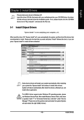
...-ROM drive, the driver CD-title will auto start and show a question mark "?" System will show the installation guide. or you can install others application. For USB2.0 driver support under "Device Manager". Install Drivers After install Windows Service Pack, it will reboot automatically after install the drivers, afterward you want and press "install" followed the item; English Chapter 3 Install Drivers Pictures below are shown in "Universal Serial Bus controller" under Windows XP operating system, please use Windows Service...
...-ROM drive, the driver CD-title will auto start and show a question mark "?" System will show the installation guide. or you can install others application. For USB2.0 driver support under "Device Manager". Install Drivers After install Windows Service Pack, it will reboot automatically after install the drivers, afterward you want and press "install" followed the item; English Chapter 3 Install Drivers Pictures below are shown in "Universal Serial Bus controller" under Windows XP operating system, please use Windows Service...
Manual
Page 54
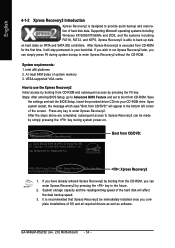
... to enter Xpress Recovery2. Boot from CD-ROM. GA-946GM-DS2/S2 (rev. 2.0) Motherboard - 54 - Upon system restart, the message which says "Boot from CD/DVD: Press any key to back up data on hard disks on . . . At least 64M bytes of OS and all required drivers as well as software. Intel x86 platforms 2. Save the settings and exit the BIOS Setup. Supporting Microsoft operating systems including Windows XP...
... to enter Xpress Recovery2. Boot from CD-ROM. GA-946GM-DS2/S2 (rev. 2.0) Motherboard - 54 - Upon system restart, the message which says "Boot from CD/DVD: Press any key to back up data on hard disks on . . . At least 64M bytes of OS and all required drivers as well as software. Intel x86 platforms 2. Save the settings and exit the BIOS Setup. Supporting Microsoft operating systems including Windows XP...
Manual
Page 57
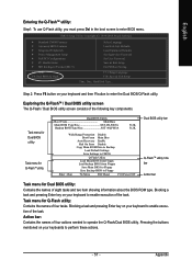
CMOS Setup Utility-Copyright (C) 1984-2004 Award Software Standard CMOS Features Advanced BIOS Features Integrated Peripherals Power Management Setup PnP/PCI Configurations PC Health Status MB Intelligent Tweaker(M.I.T.) ESC: Quit F8: Dual BIOS/Q-Flash Select Language Load Fail-Safe Defaults Load Optimized Defaults Set Supervisor Password Set User Password Save & Exit Setup Exit Without Saving F3: Change Language F10: Save & Exit Setup Time, Date, Hard Disk Type... Blocking a task and pressing Enter key on your keyboard to enable execution of four actions needed to Floppy Enter : Run...
CMOS Setup Utility-Copyright (C) 1984-2004 Award Software Standard CMOS Features Advanced BIOS Features Integrated Peripherals Power Management Setup PnP/PCI Configurations PC Health Status MB Intelligent Tweaker(M.I.T.) ESC: Quit F8: Dual BIOS/Q-Flash Select Language Load Fail-Safe Defaults Load Optimized Defaults Set Supervisor Password Set User Password Save & Exit Setup Exit Without Saving F3: Change Language F10: Save & Exit Setup Time, Date, Hard Disk Type... Blocking a task and pressing Enter key on your keyboard to enable execution of four actions needed to Floppy Enter : Run...
Manual
Page 60
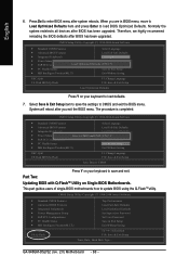
... Power Management Setup PnP/PCI Configurations PC Health Status MB Intelligent Tweaker(M.I .T.) Exit Without Saving ESC: Quit F8: Dual BIOS/Q-Flash F3: Change Language F10: Save & Exit Setup Save Data to CMOS Press Y on Single-BIOS Motherboards. Press Del to update BIOS using the Q-FlashTM utility. Select Save & Exit Setup item to CMOS and exit the BIOS menu. Part Two: Updating BIOS with Q-FlashTM Utility on your keyboard to load BIOS Optimized Defaults. This part guides users of single-BIOS motherboards how to enter BIOS menu...
... Power Management Setup PnP/PCI Configurations PC Health Status MB Intelligent Tweaker(M.I .T.) Exit Without Saving ESC: Quit F8: Dual BIOS/Q-Flash F3: Change Language F10: Save & Exit Setup Save Data to CMOS Press Y on Single-BIOS Motherboards. Press Del to update BIOS using the Q-FlashTM utility. Select Save & Exit Setup item to CMOS and exit the BIOS menu. Part Two: Updating BIOS with Q-FlashTM Utility on your keyboard to load BIOS Optimized Defaults. This part guides users of single-BIOS motherboards how to enter BIOS menu...
Manual
Page 70
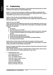
...computer problems. However, they are using is kept on standby after computer shuts down ? Press Del to the battery holder. 5. Question 5: Sometimes I cannot see these beeps usually stand for reference purposes. The situations might differ from MB. 3. AWARD BIOS Beep Codes 1 short: System boots successfully 2 short: CMOS setting error 1 long 1 short: DRAM or M/B error 1 long 2 short: Monitor or display card error 1 long 3 short: Keyboard error 1 long 9 short: BIOS ROM error Continuous long beeps: DRAM error Continuous short beeps: Power error GA-946GM-DS2/S2 (rev. 2.0) Motherboard...
...computer problems. However, they are using is kept on standby after computer shuts down ? Press Del to the battery holder. 5. Question 5: Sometimes I cannot see these beeps usually stand for reference purposes. The situations might differ from MB. 3. AWARD BIOS Beep Codes 1 short: System boots successfully 2 short: CMOS setting error 1 long 1 short: DRAM or M/B error 1 long 2 short: Monitor or display card error 1 long 3 short: Keyboard error 1 long 9 short: BIOS ROM error Continuous long beeps: DRAM error Continuous short beeps: Power error GA-946GM-DS2/S2 (rev. 2.0) Motherboard...


