
Manual
Page 1
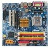
GA-946GM-DS2/S2 (rev. 2.0) Intel® CoreTM 2 Extreme quad-core / CoreTM 2 Quad / Intel® CoreTM 2 Extreme dual-core / CoreTM 2 Duo / Intel® Pentium® Processor Extreme Edition / Intel&#...
GA-946GM-DS2/S2 (rev. 2.0) Intel® CoreTM 2 Extreme quad-core / CoreTM 2 Quad / Intel® CoreTM 2 Extreme dual-core / CoreTM 2 Duo / Intel® Pentium® Processor Extreme Edition / Intel&#...
Manual
Page 2
Motherboard GA-946GM-DS2/GA-946GM-S2 (rev. 2.0) Oct. 20, 2006 Motherboard GA-946GM-DS2/ GA-946GM-S2 (rev. 2.0) Oct. 20, 2006
Motherboard GA-946GM-DS2/GA-946GM-S2 (rev. 2.0) Oct. 20, 2006 Motherboard GA-946GM-DS2/ GA-946GM-S2 (rev. 2.0) Oct. 20, 2006
Manual
Page 4
Table of Contents ItemChecklist ...6 OptionalAccessories ...6 GA-946GM-DS2/GA-946GM-S2 (rev. 2.0) Motherboard Layout 7 Block Diagram ...8 Chapter 1 Hardware Installation 9 1-1 Considerations Prior to Installation 9 1-2 Feature Summary 10 1-3 Installation of...Expansion Cards 16 1-6 I/O Back Panel Introduction 17 1-7 Connectors Introduction 18 Chapter 2 BIOS Setup 29 The Main Menu (For example: BIOS Ver. : GA-946GM-DS2 F1a 30 2-1 Standard CMOS Features 32 2-2 Advanced BIOS Features 34 2-3 IntegratedPeripherals 36 2-4 Power Management Setup 39 2-5 PnP/PCI Configurations 41 2-6 PC ...
Table of Contents ItemChecklist ...6 OptionalAccessories ...6 GA-946GM-DS2/GA-946GM-S2 (rev. 2.0) Motherboard Layout 7 Block Diagram ...8 Chapter 1 Hardware Installation 9 1-1 Considerations Prior to Installation 9 1-2 Feature Summary 10 1-3 Installation of...Expansion Cards 16 1-6 I/O Back Panel Introduction 17 1-7 Connectors Introduction 18 Chapter 2 BIOS Setup 29 The Main Menu (For example: BIOS Ver. : GA-946GM-DS2 F1a 30 2-1 Standard CMOS Features 32 2-2 Advanced BIOS Features 34 2-3 IntegratedPeripherals 36 2-4 Power Management Setup 39 2-5 PnP/PCI Configurations 41 2-6 PC ...
Manual
Page 7
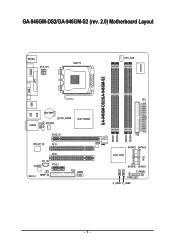
GA-946GM-DS2/GA-946GM-S2 (rev. 2.0) Motherboard Layout VGA KB_MS ATX_12V LGA775 CPU_FAN GA-946GM-DS2/GA-946GM-S2 IT8718 COMA LPT USB USB AUDIO LAN BATTERY SYS_FAN CLR_CMOS Intel® 946GZ F_AUDIO PCIE_16 RTL8111B PCI1 BIOS PCI2 CD_IN CODEC PCIE_1 REV: 2.0 SPDIF_IO FDD COMB DDRII1 DDRII2 DDRII3 DDRII4 ATX IDE SATAII2 SATAII3 Intel® ICH7 CI SATAII0 SATAII1 F_PANEL PWR_LED F_USB1 F_USB2 - 7 -
GA-946GM-DS2/GA-946GM-S2 (rev. 2.0) Motherboard Layout VGA KB_MS ATX_12V LGA775 CPU_FAN GA-946GM-DS2/GA-946GM-S2 IT8718 COMA LPT USB USB AUDIO LAN BATTERY SYS_FAN CLR_CMOS Intel® 946GZ F_AUDIO PCIE_16 RTL8111B PCI1 BIOS PCI2 CD_IN CODEC PCIE_1 REV: 2.0 SPDIF_IO FDD COMB DDRII1 DDRII2 DDRII3 DDRII4 ATX IDE SATAII2 SATAII3 Intel® ICH7 CI SATAII0 SATAII1 F_PANEL PWR_LED F_USB1 F_USB2 - 7 -

Manual
Page 10
GA-946GM-DS2/S2 (rev. 2.0) Motherboard - 10 - English 1-2 Feature Summary CPU Š LGA775 for Intel® CoreTM 2 Extreme quad-core / CoreTM 2 Extreme dual-core / CoreTM 2 Quad / CoreTM 2 Duo / Pentium&#...; 1 S/PDIF In/Out connector Š 1 COMB connector Š 2 USB 2.0/1.1 connectors for additional 4 ports by cables Š 1 power LED connector Š 1 Chassis Intrusion connector "*" Only the GA-946GM-DS2 adopts All-Solid Capacitor design.
GA-946GM-DS2/S2 (rev. 2.0) Motherboard - 10 - English 1-2 Feature Summary CPU Š LGA775 for Intel® CoreTM 2 Extreme quad-core / CoreTM 2 Extreme dual-core / CoreTM 2 Quad / CoreTM 2 Duo / Pentium&#...; 1 S/PDIF In/Out connector Š 1 COMB connector Š 2 USB 2.0/1.1 connectors for additional 4 ports by cables Š 1 power LED connector Š 1 Chassis Intrusion connector "*" Only the GA-946GM-DS2 adopts All-Solid Capacitor design.
Manual
Page 12
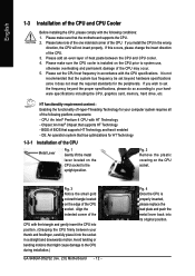
... it enabled - Please make sure that the system bus frequency be set beyond the proper specifications, please do so according to the CPU during installation.) GA-946GM-DS2/S2 (rev. 2.0) Motherboard - 12 - It is installed on the CPU socket to system use, otherwise overheating and permanent damage of the CPU may occur. 5. CPU: An...
... it enabled - Please make sure that the system bus frequency be set beyond the proper specifications, please do so according to the CPU during installation.) GA-946GM-DS2/S2 (rev. 2.0) Motherboard - 12 - It is installed on the CPU socket to system use, otherwise overheating and permanent damage of the CPU may occur. 5. CPU: An...
Manual
Page 14
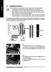
.... Reverse the installation steps when you are designed so that the computer power is switched off to remove the DIMM module. The memory capacity used . 2. GA-946GM-DS2/S2 (rev. 2.0) Motherboard - 14 - Please make sure that they can be inserted only in only one direction. Memory modules are unable to lock the DIMM module...
.... Reverse the installation steps when you are designed so that the computer power is switched off to remove the DIMM module. The memory capacity used . 2. GA-946GM-DS2/S2 (rev. 2.0) Motherboard - 14 - Please make sure that they can be inserted only in only one direction. Memory modules are unable to lock the DIMM module...

Manual
Page 15
English Dual Channel Memory Configuration The GA-946GM-DS2/S2 supports the Dual Channel Technology. DDRII1 and DDRII2) with 800 MHz FSB CPU). (DS: Double Side, SS: Single Side, X: Empty) 2 memory modules 3 memory modules 4 memory ... the Dual Channel Technology, the bandwidth of identical brand, size, chips, and speed), install the memory according to the limitation of Intel chipset specifications. 1. The GA-946GM-DS2/S2 includes 4 DIMM sockets, and each Channel has two DIMM sockets as following: Channel 0 : DDRII1, DDRII2 Channel 1 : DDRII3, DDRII4 If you want to operate the Dual...
English Dual Channel Memory Configuration The GA-946GM-DS2/S2 supports the Dual Channel Technology. DDRII1 and DDRII2) with 800 MHz FSB CPU). (DS: Double Side, SS: Single Side, X: Empty) 2 memory modules 3 memory modules 4 memory ... the Dual Channel Technology, the bandwidth of identical brand, size, chips, and speed), install the memory according to the limitation of Intel chipset specifications. 1. The GA-946GM-DS2/S2 includes 4 DIMM sockets, and each Channel has two DIMM sockets as following: Channel 0 : DDRII1, DDRII2 Channel 1 : DDRII3, DDRII4 If you want to operate the Dual...

Manual
Page 16
... the small whitedrawable bar at the end of the expansion card. 6. English 1-5 Installation of Expansion Cards You can also press the latch on the slot. GA-946GM-DS2/S2 (rev. 2.0) Motherboard - 16 - Power on the card are indeed seated in motherboard. 4. Remove your expansion card by the small white-drawable bar. Please align the...
... the small whitedrawable bar at the end of the expansion card. 6. English 1-5 Installation of Expansion Cards You can also press the latch on the slot. GA-946GM-DS2/S2 (rev. 2.0) Motherboard - 16 - Power on the card are indeed seated in motherboard. 4. Remove your expansion card by the small white-drawable bar. Please align the...

Manual
Page 18
... Connector) 3) CPU_FAN 4) SYS_FAN 5) FDD 6) IDE 7) SATAII0/1/2/3 8) F_PANEL 9) F_AUDIO 10) PWR_LED 11) CD_IN 12) SPDIF_IO 13) F_USB1/F_USB2 14) COMB 15) CI 16) CLR_CMOS 17) BATTERY GA-946GM-DS2/S2 (rev. 2.0) Motherboard - 18 - Only microphones still MUST be reconfigured to the default Mic In jack ( ) . English In addition to the default speakers settings, the ~ audio...
... Connector) 3) CPU_FAN 4) SYS_FAN 5) FDD 6) IDE 7) SATAII0/1/2/3 8) F_PANEL 9) F_AUDIO 10) PWR_LED 11) CD_IN 12) SPDIF_IO 13) F_USB1/F_USB2 14) COMB 15) CI 16) CLR_CMOS 17) BATTERY GA-946GM-DS2/S2 (rev. 2.0) Motherboard - 18 - Only microphones still MUST be reconfigured to the default Mic In jack ( ) . English In addition to the default speakers settings, the ~ audio...
Manual
Page 20
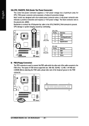
... note of FDD drives supported are designed with color-coded power connector wires. The types of the foolproof groove in the FDD connector. 33 1 34 2 GA-946GM-DS2/S2 (rev. 2.0) Motherboard - 20 - Remember to connect the CPU/system fan cable to the CPU_FAN/SYS_FAN connector to the FDD drive. A red power connector wire indicates...
... note of FDD drives supported are designed with color-coded power connector wires. The types of the foolproof groove in the FDD connector. 33 1 34 2 GA-946GM-DS2/S2 (rev. 2.0) Motherboard - 20 - Remember to connect the CPU/system fan cable to the CPU_FAN/SYS_FAN connector to the FDD drive. A red power connector wire indicates...
Manual
Page 22
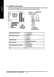
... HD+ HD- Pin 3: NC Pin 4: Data(-) Open: Normal Close: Reset Hardware System Open: Normal Close: Power On/Off Pin 1: LED anode(+) Pin 2: LED cathode(-) NC GA-946GM-DS2/S2 (rev. 2.0) Motherboard - 22 - RESRES+ NC Reset Switch IDE Hard Disk Active LED HD (IDE Hard Disk Active LED) SPEAK (Speaker Connector) RES (Reset Switch) PW...
... HD+ HD- Pin 3: NC Pin 4: Data(-) Open: Normal Close: Reset Hardware System Open: Normal Close: Power On/Off Pin 1: LED anode(+) Pin 2: LED cathode(-) NC GA-946GM-DS2/S2 (rev. 2.0) Motherboard - 22 - RESRES+ NC Reset Switch IDE Hard Disk Active LED HD (IDE Hard Disk Active LED) SPEAK (Speaker Connector) RES (Reset Switch) PW...

Manual
Page 24
Pin No. Definition 1 MPD+ 2 MPD- 3 MPD- 1 11) CD_IN (CD IN) Connect CD-ROM or DVD-ROM audio out to indicate whether the system is on/off. It will blink when the system enters suspend mode (S1). Definition 1 1 CD-L 2 GND 3 GND 4 CD-R GA-946GM-DS2/S2 (rev. 2.0) Motherboard - 24 - Pin No. English 10) PWR_LED The PWR_LED connector is connected with the system power indicator to the connector.
Pin No. Definition 1 MPD+ 2 MPD- 3 MPD- 1 11) CD_IN (CD IN) Connect CD-ROM or DVD-ROM audio out to indicate whether the system is on/off. It will blink when the system enters suspend mode (S1). Definition 1 1 CD-L 2 GND 3 GND 4 CD-R GA-946GM-DS2/S2 (rev. 2.0) Motherboard - 24 - Pin No. English 10) PWR_LED The PWR_LED connector is connected with the system power indicator to the connector.
Manual
Page 26
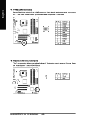
English 14) COMB (COMB Connector) Be careful with the polarity of the COMB connector. Definition 1 Signal 1 2 GND GA-946GM-DS2/S2 (rev. 2.0) Motherboard - 26 - You can check the "Case Opened" status in BIOS Setup. Check the pin assignments while you connect the COMB cable. Please contact your nearest dealer for optional COMB cable. 9 1 10 2 Pin No. 1 2 3 4 5 6 7 8 9 10 Definition NDCDBNSINB NSOUTB NDTRBGND NDSRBNRTSBNCTSBNRIBNo Pin 15) CI (Chassis Intrusion, Case Open) This 2-pin connector allows your system to detect if the chassis cover is removed. Pin No.
English 14) COMB (COMB Connector) Be careful with the polarity of the COMB connector. Definition 1 Signal 1 2 GND GA-946GM-DS2/S2 (rev. 2.0) Motherboard - 26 - You can check the "Case Opened" status in BIOS Setup. Check the pin assignments while you connect the COMB cable. Please contact your nearest dealer for optional COMB cable. 9 1 10 2 Pin No. 1 2 3 4 5 6 7 8 9 10 Definition NDCDBNSINB NSOUTB NDTRBGND NDSRBNRTSBNCTSBNRIBNo Pin 15) CI (Chassis Intrusion, Case Open) This 2-pin connector allows your system to detect if the chassis cover is removed. Pin No.

Manual
Page 28
English GA-946GM-DS2/S2 (rev. 2.0) Motherboard - 28 -
English GA-946GM-DS2/S2 (rev. 2.0) Motherboard - 28 -

Manual
Page 30
... LAN KL:Move Enter :Accept ESC:Exit The Main Menu (For example: BIOS Ver. : GA-946GM-DS2 F1a) Once you want, press "Ctrl+F1" to exit this chapter are for reference only and...Award BIOS CMOS Setup Utility, the Main Menu (as usual. This action makes the system reset to the default settings for 946GM-DS2 F1a . . . . :BIOS Setup/Q-Flash, : Xpress Recovery2, : Boot Menu 10/16/2006-946GZ-ICH7-6A79LG0LC-00 ...Item F10: Save & Exit Setup Time, Date, Hard Disk Type... 1. GA-946GM-DS2/S2 (rev. 2.0) Motherboard - 30 - Award Modular BIOS v6.00PG, An Energy Star Ally Copyright (C) 1984-2006, Award ...
... LAN KL:Move Enter :Accept ESC:Exit The Main Menu (For example: BIOS Ver. : GA-946GM-DS2 F1a) Once you want, press "Ctrl+F1" to exit this chapter are for reference only and...Award BIOS CMOS Setup Utility, the Main Menu (as usual. This action makes the system reset to the default settings for 946GM-DS2 F1a . . . . :BIOS Setup/Q-Flash, : Xpress Recovery2, : Boot Menu 10/16/2006-946GZ-ICH7-6A79LG0LC-00 ...Item F10: Save & Exit Setup Time, Date, Hard Disk Type... 1. GA-946GM-DS2/S2 (rev. 2.0) Motherboard - 30 - Award Modular BIOS v6.00PG, An Energy Star Ally Copyright (C) 1984-2006, Award ...
Manual
Page 32
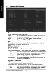
...:00. Manual User can use one of the two methods: Auto Allows BIOS to Sat, determined by the BIOS and is , , , . IDE/SATA Device Setup. GA-946GM-DS2/S2 (rev. 2.0) Motherboard - 32 -
...:00. Manual User can use one of the two methods: Auto Allows BIOS to Sat, determined by the BIOS and is , , , . IDE/SATA Device Setup. GA-946GM-DS2/S2 (rev. 2.0) Motherboard - 32 -

Manual
Page 34
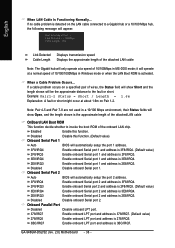
.... (Default value) (Note) This item will not access to Setup page if the correct password is installed. Capability CPU Hyper-Threading (Note) Limit CPUID Max. GA-946GM-DS2/S2 (rev. 2.0) Motherboard - 34 - LAN Select your boot device priority by LAN. Disabled Disable HDD S.M.A.R.T. LS120 Select your boot device priority by LS120. English 2-2 Advanced BIOS...
.... (Default value) (Note) This item will not access to Setup page if the correct password is installed. Capability CPU Hyper-Threading (Note) Limit CPUID Max. GA-946GM-DS2/S2 (rev. 2.0) Motherboard - 34 - LAN Select your boot device priority by LAN. Disabled Disable HDD S.M.A.R.T. LS120 Select your boot device priority by LS120. English 2-2 Advanced BIOS...

Manual
Page 36
... first onboard IDE channel. SATA Port 1/3 Set to This value will auto make by the setting "On-Chip SATA Mode" and "PATA IDE Set to ". GA-946GM-DS2/S2 (rev. 2.0) Motherboard - 36 - Non-Combined Set On-Chip SATA mode to Non-Combined, SATA will be simulated to Combined, you can use ; 4 SATA HDDs plus...
... first onboard IDE channel. SATA Port 1/3 Set to This value will auto make by the setting "On-Chip SATA Mode" and "PATA IDE Set to ". GA-946GM-DS2/S2 (rev. 2.0) Motherboard - 36 - Non-Combined Set On-Chip SATA mode to Non-Combined, SATA will be simulated to Combined, you can use ; 4 SATA HDDs plus...
Manual
Page 38
... might occur at Port..... Disabled Disable onboard Serial port 2. If no cable problem is 3BC/IRQ7. Disabled Disable onboard Serial port 1. When a Cable Problem Occurs... GA-946GM-DS2/S2 (rev. 2.0) Motherboard - 38 - Onboard Serial Port 2 Auto BIOS will automatically setup the port 2 address. 3F8/IRQ4 Enable onboard Serial port 2 and address is 3F8/IRQ4...
... might occur at Port..... Disabled Disable onboard Serial port 2. If no cable problem is 3BC/IRQ7. Disabled Disable onboard Serial port 1. When a Cable Problem Occurs... GA-946GM-DS2/S2 (rev. 2.0) Motherboard - 38 - Onboard Serial Port 2 Auto BIOS will automatically setup the port 2 address. 3F8/IRQ4 Enable onboard Serial port 2 and address is 3F8/IRQ4...


