Manual
Page 4
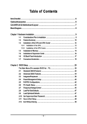
...GA-945PLM-S2 Motherboard Layout 7 Block Diagram ...8 Chapter 1 Hardware Installation 9 1-1 Considerations Prior to Installation 9 1-2 Feature Summary 10 1-3 Installation of the CPU and CPU Cooler 12 1-3-1 Installation of the CPU 12 1-3-2 Installation of the CPU Cooler 13 1-4 Installation of Memory 14 1-5 Installation of Expansion Cards 16 1-6 I/O Back Panel Introduction 17 1-7 Connectors Introduction 18 Chapter 2 BIOS... Setup 29 The Main Menu (For example: BIOS Ver. : FI 30 2-1 Standard CMOS Features 32 2-2 Advanced BIOS Features 34 2-3 ...
...GA-945PLM-S2 Motherboard Layout 7 Block Diagram ...8 Chapter 1 Hardware Installation 9 1-1 Considerations Prior to Installation 9 1-2 Feature Summary 10 1-3 Installation of the CPU and CPU Cooler 12 1-3-1 Installation of the CPU 12 1-3-2 Installation of the CPU Cooler 13 1-4 Installation of Memory 14 1-5 Installation of Expansion Cards 16 1-6 I/O Back Panel Introduction 17 1-7 Connectors Introduction 18 Chapter 2 BIOS... Setup 29 The Main Menu (For example: BIOS Ver. : FI 30 2-1 Standard CMOS Features 32 2-2 Advanced BIOS Features 34 2-3 ...

Manual
Page 5
Channel Audio Function Introduction 62 4-2 Troubleshooting 68 - 5 - Chapter 3 Install Drivers 51 3-1 Install Chipset Drivers 51 3-2 SoftwareApplications 52 3-3 Driver CD Information 52 3-4 Hardware Information 53 3-5 Contact Us ...53 Chapter 4 Appendix 55 4-1 Unique Software Utilities 55 4-1-1 EasyTune 5 Introduction 55 4-1-2 Xpress Recovery2 Introduction 56 4-1-3 Flash BIOS Method Introduction 58 4-1-4 2- / 4- / 6- / 8-
Channel Audio Function Introduction 62 4-2 Troubleshooting 68 - 5 - Chapter 3 Install Drivers 51 3-1 Install Chipset Drivers 51 3-2 SoftwareApplications 52 3-3 Driver CD Information 52 3-4 Hardware Information 53 3-5 Contact Us ...53 Chapter 4 Appendix 55 4-1 Unique Software Utilities 55 4-1-1 EasyTune 5 Introduction 55 4-1-2 Xpress Recovery2 Introduction 56 4-1-3 Flash BIOS Method Introduction 58 4-1-4 2- / 4- / 6- / 8-
Manual
Page 7
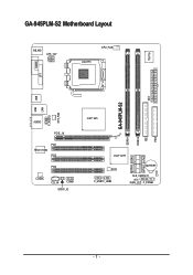
GA-945PLM-S2 Motherboard Layout KB_MS ATX_12V CPU_FAN LGA775 IT8718 COMA LPT DDRII2 IDE ATX FDD USB GA-945PLM-S2 LAN USB SYS_FAN F_AUDIO AUDIO PCIE_16 PCI1 RTL8110SC PCI2 PCI3 CODEC CD_IN COMB SPDIF_IO Intel® 945 DDRII1 SATAII0 SATAII2 SATAII1 SATAII3 Intel® ICH7 BIOS F_USB1 F_USB2 BATTERY CLR_CMOS CI PWR_LED F_PANEL - 7 -
GA-945PLM-S2 Motherboard Layout KB_MS ATX_12V CPU_FAN LGA775 IT8718 COMA LPT DDRII2 IDE ATX FDD USB GA-945PLM-S2 LAN USB SYS_FAN F_AUDIO AUDIO PCIE_16 PCI1 RTL8110SC PCI2 PCI3 CODEC CD_IN COMB SPDIF_IO Intel® 945 DDRII1 SATAII0 SATAII2 SATAII1 SATAII3 Intel® ICH7 BIOS F_USB1 F_USB2 BATTERY CLR_CMOS CI PWR_LED F_PANEL - 7 -

Manual
Page 8
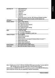
...(Note 2) Dual Channel Memory PCI Bus x1 RTL 8110SC RJ45 LAN 3 PCI PCI CLK (33 MHz) Intel® ICH7 ATA-33/66/100 IDE Channel BIOS 4 SATA 3Gb/s 8 USB Ports CODEC IT8718 Floppy LPT Port COM Ports PS/2 KB/Mouse Surround Speaker Out Center/Subwoofer Speaker Out Side Speaker Out MIC...
...(Note 2) Dual Channel Memory PCI Bus x1 RTL 8110SC RJ45 LAN 3 PCI PCI CLK (33 MHz) Intel® ICH7 ATA-33/66/100 IDE Channel BIOS 4 SATA 3Gb/s 8 USB Ports CODEC IT8718 Floppy LPT Port COM Ports PS/2 KB/Mouse Surround Speaker Out Center/Subwoofer Speaker Out Side Speaker Out MIC...
Manual
Page 11
...CPU / System fan failure warning Š CPU smart fan control BIOS Š 1 4 Mbit flash ROM Š Use of licensed AWARD BIOS Š PnP 1.0a, DMI 2.0, SM BIOS 2.3, ACPI 1.0b Additional Features Š Supports @BIOS Š Supports Download Center Š Supports Q-Flash Š Supports... EasyTune (only supports Hardware Monitor function)(Note 3) Š Supports Xpress Install Š Supports Xpress Recovery2 Š Supports Xpress BIOS Rescue Bundle Software Š Norton Internet Security (OEM revision) Form Factor Š Micro ATX form factor; 22.0cm x 24.4cm ...
...CPU / System fan failure warning Š CPU smart fan control BIOS Š 1 4 Mbit flash ROM Š Use of licensed AWARD BIOS Š PnP 1.0a, DMI 2.0, SM BIOS 2.3, ACPI 1.0b Additional Features Š Supports @BIOS Š Supports Download Center Š Supports Q-Flash Š Supports... EasyTune (only supports Hardware Monitor function)(Note 3) Š Supports Xpress Install Š Supports Xpress Recovery2 Š Supports Xpress BIOS Rescue Bundle Software Š Norton Internet Security (OEM revision) Form Factor Š Micro ATX form factor; 22.0cm x 24.4cm ...
Manual
Page 12
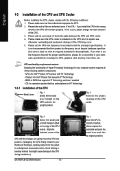
...of the CPU with the following platform components: - If you wish to set the CPU host frequency in a straight and downwards motion. BIOS: A BIOS that supports HT Technology - Please make sure that might cause damage to the upright position. Align the indented corner of the CPU. ... specifications since it enabled - Fig. 3 Notice the small gold colored triangle located on the CPU socket to the CPU during installation.) GA-945PLM-S2 Motherboard - 12 - Please make sure the CPU cooler is properly inserted, please replace the load plate and push the metal lever back...
...of the CPU with the following platform components: - If you wish to set the CPU host frequency in a straight and downwards motion. BIOS: A BIOS that supports HT Technology - Please make sure that might cause damage to the upright position. Align the indented corner of the CPU. ... specifications since it enabled - Fig. 3 Notice the small gold colored triangle located on the CPU socket to the CPU during installation.) GA-945PLM-S2 Motherboard - 12 - Please make sure the CPU cooler is properly inserted, please replace the load plate and push the metal lever back...

Manual
Page 14
The memory capacity used can be installed in only one direction. GA-945PLM-S2 Motherboard - 14 - If you wish to prevent hardware damage. 3. Fig.2 Close the plastic clip at both edges of the DIMM sockets to insert the module, ... memory modules, please comply with each slot. Please make sure that they can only fit in one direction. The motherboard supports DDR2 memory modules, whereby BIOS will automatically detect memory capacity and specifications. Then push it down.
The memory capacity used can be installed in only one direction. GA-945PLM-S2 Motherboard - 14 - If you wish to prevent hardware damage. 3. Fig.2 Close the plastic clip at both edges of the DIMM sockets to insert the module, ... memory modules, please comply with each slot. Please make sure that they can only fit in one direction. The motherboard supports DDR2 memory modules, whereby BIOS will automatically detect memory capacity and specifications. Then push it down.
Manual
Page 16
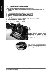
... back on the black lever on the top edge of expansion card from the computer. 3. Replace your computer's chassis cover, screws and slot bracket from BIOS. 8. For example: Installing a PCI Express x16 VGA card: When installing the graphics card, push down on the slot and then lift the card straight out... card. 6. Make sure the card is fully inserted into the PCI Express x16 slot. Be sure the metal contacts on the computer, if necessary, setup BIOS utility of the card until it is securely seated in motherboard. 4. GA-945PLM-S2 Motherboard - 16 -
... back on the black lever on the top edge of expansion card from the computer. 3. Replace your computer's chassis cover, screws and slot bracket from BIOS. 8. For example: Installing a PCI Express x16 VGA card: When installing the graphics card, push down on the slot and then lift the card straight out... card. 6. Make sure the card is fully inserted into the PCI Express x16 slot. Be sure the metal contacts on the computer, if necessary, setup BIOS utility of the card until it is securely seated in motherboard. 4. GA-945PLM-S2 Motherboard - 16 -

Manual
Page 21
...). Before attaching the IDE cable, please take note of the foolproof groove in order to the computer via an IDE connector. Please refer to the BIOS setting for information on settings, please refer to the instructions located on one IDE cable, and the single IDE cable can provide up to 300...
...). Before attaching the IDE cable, please take note of the foolproof groove in order to the computer via an IDE connector. Please refer to the BIOS setting for information on settings, please refer to the instructions located on one IDE cable, and the single IDE cable can provide up to 300...

Manual
Page 27
Hardware Installation Pin No. You can check the "Case Opened" status in BIOS Setup. Definition 1 Signal 1 2 GND - 27 - English 17) CI (Chassis Intrusion, Case Open) This 2-pin connector allows your system to detect if the chassis cover is removed.
Hardware Installation Pin No. You can check the "Case Opened" status in BIOS Setup. Definition 1 Signal 1 2 GND - 27 - English 17) CI (Chassis Intrusion, Case Open) This 2-pin connector allows your system to detect if the chassis cover is removed.
Manual
Page 29
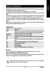
.... When the power is turned on, press the button during the BIOS POST (Power-On Self Test) will take you wish to upgrade to the CMOS SETUP screen. If you to a new BIOS, either GIGABYTE's Q-Flash or @BIOS utility can enter the BIOS setup screen by pressing "Ctrl + F1". Quit and not save ...changes into CMOS Status Page Setup Menu and Option Page Setup Menu - Because BIOS flashing is potentially risky, please do it with caution ...
.... When the power is turned on, press the button during the BIOS POST (Power-On Self Test) will take you wish to upgrade to the CMOS SETUP screen. If you to a new BIOS, either GIGABYTE's Q-Flash or @BIOS utility can enter the BIOS setup screen by pressing "Ctrl + F1". Quit and not save ...changes into CMOS Status Page Setup Menu and Option Page Setup Menu - Because BIOS flashing is potentially risky, please do it with caution ...

Manual
Page 30
..., Award Software, Inc. Select the Load Optimized Defaults item in this menu. GA-945PLM-S2 Motherboard - 30 - Press to accept . CMOS Setup Utility-Copyright (C) 1984-2007 Award Software ` Standard CMOS Features ` Advanced BIOS Features ` Integrated Peripherals ` Power Management Setup ` PnP/PCI Configurations ` PC ... want, press "Ctrl+F1" to accept or enter the sub-menu. This action makes the system reset to the default settings for 945PLM-S2 FI . . . . :BIOS Setup/Q-Flash :XpressRecovery2 :Boot Menu :Qflash 06/20/2007-I945-6A79TG0LC-00 : Boot Menu Use < > or < > to select...
..., Award Software, Inc. Select the Load Optimized Defaults item in this menu. GA-945PLM-S2 Motherboard - 30 - Press to accept . CMOS Setup Utility-Copyright (C) 1984-2007 Award Software ` Standard CMOS Features ` Advanced BIOS Features ` Integrated Peripherals ` Power Management Setup ` PnP/PCI Configurations ` PC ... want, press "Ctrl+F1" to accept or enter the sub-menu. This action makes the system reset to the default settings for 945PLM-S2 FI . . . . :BIOS Setup/Q-Flash :XpressRecovery2 :Boot Menu :Qflash 06/20/2007-I945-6A79TG0LC-00 : Boot Menu Use < > or < > to select...

Manual
Page 31
...CMOS Features This setup page includes all the items in best performance configuration. „ Set Supervisor Password Change, set , or disable password. BIOS Setup It allows you to limit access to the system. „ Save & Exit Setup Save CMOS value settings to Setup. „ ...„ Load Optimized Defaults Optimized Defaults indicates the value of the system parameters which the system would be in standard compatible BIOS. „ Advanced BIOS Features This setup page includes all the items of Award special enhanced features. „ Integrated Peripherals This setup page includes all...
...CMOS Features This setup page includes all the items in best performance configuration. „ Set Supervisor Password Change, set , or disable password. BIOS Setup It allows you to limit access to the system. „ Save & Exit Setup Save CMOS value settings to Setup. „ ...„ Load Optimized Defaults Optimized Defaults indicates the value of the system parameters which the system would be in standard compatible BIOS. „ Advanced BIOS Features This setup page includes all the items of Award special enhanced features. „ Integrated Peripherals This setup page includes all...

Manual
Page 32
is calculated base on the 24-hour military- GA-945PLM-S2 Motherboard - 32 - Through Dec. Day The day, from 1 to 31 (or...are : CHS/LBA/Large/Auto(default:Auto) Capacity Capacity of the two methods: • Auto Allows BIOS to select this if no IDE/SATA devices are used and the system will skip the automatic detection step ... hard drive. IDE Channel 0 Master/Slave IDE HDD Auto-Detection Press "Enter" to select this to Sat, determined by the BIOS and is , , , . For example, 1 p.m. You can manually input the correct settings. IDE Channel 0 Master/Slave IDE...
is calculated base on the 24-hour military- GA-945PLM-S2 Motherboard - 32 - Through Dec. Day The day, from 1 to 31 (or...are : CHS/LBA/Large/Auto(default:Auto) Capacity Capacity of the two methods: • Auto Allows BIOS to select this if no IDE/SATA devices are used and the system will skip the automatic detection step ... hard drive. IDE Channel 0 Master/Slave IDE HDD Auto-Detection Press "Enter" to select this to Sat, determined by the BIOS and is , , , . For example, 1 p.m. You can manually input the correct settings. IDE Channel 0 Master/Slave IDE...

Manual
Page 33
... disk error; The value of the base memory is the amount of memory located above 1 MB in the CPU's memory address map. - 33 - BIOS Setup This is typically 512 K for systems with 512 K memory installed on the motherboard. The two options are: Large/Auto(default:Auto) Capacity Capacity... a non-fatal error the system will stop for the hard drive. Base Memory The POST of the BIOS will determine the amount of the BIOS. Extended Memory The BIOS determines how much extended memory is determined by POST (Power On Self Test) of base (or conventional) memory installed in...
... disk error; The value of the base memory is the amount of memory located above 1 MB in the CPU's memory address map. - 33 - BIOS Setup This is typically 512 K for systems with 512 K memory installed on the motherboard. The two options are: Large/Auto(default:Auto) Capacity Capacity... a non-fatal error the system will stop for the hard drive. Base Memory The POST of the BIOS will determine the amount of the BIOS. Extended Memory The BIOS determines how much extended memory is determined by POST (Power On Self Test) of base (or conventional) memory installed in...

Manual
Page 34
... priority by USB-FDD. LS120 Hard Disk Select your boot device priority by LS120. Select your boot device priority by USB-ZIP. GA-945PLM-S2 Motherboard - 34 - Press to Setup will be denied if the correct password is not entered at the prompt. Setup The system ...and can not access to Setup page will boot, but access to exit this function. English 2-2 Advanced BIOS Features CMOS Setup Utility-Copyright (C) 1984-2007 Award Software Advanced BIOS Features ` Hard Disk Boot Priority First Boot Device Second Boot Device Third Boot Device Password Check HDD S.M.A.R.T....
... priority by USB-FDD. LS120 Hard Disk Select your boot device priority by LS120. Select your boot device priority by USB-ZIP. GA-945PLM-S2 Motherboard - 34 - Press to Setup will be denied if the correct password is not entered at the prompt. Setup The system ...and can not access to Setup page will boot, but access to exit this function. English 2-2 Advanced BIOS Features CMOS Setup Utility-Copyright (C) 1984-2007 Award Software Advanced BIOS Features ` Hard Disk Boot Priority First Boot Device Second Boot Device Third Boot Device Password Check HDD S.M.A.R.T....

Manual
Page 35
... that this function. - 35 - CPU Enhanced Halt (C1E) (Note) Enabled Enable CPU Enhanced Halt (C1E) function. (Default value) Disabled Disable CPU Enhanced Halt (C1E) function. BIOS Setup CPU Thermal Monitor 2 (TM2) (Note) Enabled Enable CPU Thermal Monitor 2 (TM2) function. (Default value) Disabled Disable CPU Thermal Monitor 2 (TM2) function. Virtualization Technology (Note...
... that this function. - 35 - CPU Enhanced Halt (C1E) (Note) Enabled Enable CPU Enhanced Halt (C1E) function. (Default value) Disabled Disable CPU Enhanced Halt (C1E) function. BIOS Setup CPU Thermal Monitor 2 (TM2) (Note) Enabled Enable CPU Thermal Monitor 2 (TM2) function. (Default value) Disabled Disable CPU Thermal Monitor 2 (TM2) function. Virtualization Technology (Note...

Manual
Page 36
... ". SATA Port 0/2 Set to This value will auto make by the setting "On-Chip SATA Mode" and "PATA IDE Set to Combined or Enhanced mode. GA-945PLM-S2 Motherboard - 36 - SATA Port 1/3 Set to This value will auto make by the setting "On-Chip SATA Mode" and "PATA IDE Set to Ch. ...Enhanced plus two SATA devices. If PATA IDE were set to Ch. 1 Master/Slave, this function will auto set SATA devices to ". Auto Lets BIOS set to USB Controller USB 2.0 Controller USB Keyboard Support USB Mouse Support Legacy USB storage detect Azalia Codec Onboard H/W LAN ` SMART LAN Onboard LAN ...
... ". SATA Port 0/2 Set to This value will auto make by the setting "On-Chip SATA Mode" and "PATA IDE Set to Combined or Enhanced mode. GA-945PLM-S2 Motherboard - 36 - SATA Port 1/3 Set to This value will auto make by the setting "On-Chip SATA Mode" and "PATA IDE Set to Ch. ...Enhanced plus two SATA devices. If PATA IDE were set to Ch. 1 Master/Slave, this function will auto set SATA devices to ". Auto Lets BIOS set to USB Controller USB 2.0 Controller USB Keyboard Support USB Mouse Support Legacy USB storage detect Azalia Codec Onboard H/W LAN ` SMART LAN Onboard LAN ...

Manual
Page 37
... Onboard H/W LAN Enabled Enable onboard H/W LAN function. (Default value) Disabled Disable this function if you are not using onboard USB 2.0 feature. BIOS Setup Disable USB mouse support. (Default value) Legacy USB storage detect This option allows users to decide whether to detect USB storage devices, including ...USB Keyboard Support Enabled Enable USB keyboard support. English USB Controller Enabled Enable USB controller. (Default value) Disabled Disable USB controller. Enabled Disabled BIOS will scan all USB storage devices. (Default value) Disable this function.
... Onboard H/W LAN Enabled Enable onboard H/W LAN function. (Default value) Disabled Disable this function if you are not using onboard USB 2.0 feature. BIOS Setup Disable USB mouse support. (Default value) Legacy USB storage detect This option allows users to decide whether to detect USB storage devices, including ...USB Keyboard Support Enabled Enable USB keyboard support. English USB Controller Enabled Enable USB controller. (Default value) Disabled Disable USB controller. Enabled Disabled BIOS will scan all USB storage devices. (Default value) Disable this function.

Manual
Page 39
... 3BC/IRQ7 Enable onboard LPT port and address is 2E8/IRQ3. Enabled Enable this function. (Default value) Onboard Serial Port 1 Auto BIOS will automatically setup the port 2 address. 3F8/IRQ4 Enable onboard Serial port 2 and address is 3F8/IRQ4. 2F8/IRQ3 Enable onboard Serial...2. Parallel Port Mode SPP Using Parallel port as Standard Parallel Port. (Default value) EPP Using Parallel port as Extended Capabilities Port. BIOS Setup ECP Using Parallel port as Enhanced Parallel Port. Disabled Disable onboard Serial port 1. ECP+EPP Using Parallel port as ECP & ...
... 3BC/IRQ7 Enable onboard LPT port and address is 2E8/IRQ3. Enabled Enable this function. (Default value) Onboard Serial Port 1 Auto BIOS will automatically setup the port 2 address. 3F8/IRQ4 Enable onboard Serial port 2 and address is 3F8/IRQ4. 2F8/IRQ3 Enable onboard Serial...2. Parallel Port Mode SPP Using Parallel port as Standard Parallel Port. (Default value) EPP Using Parallel port as Extended Capabilities Port. BIOS Setup ECP Using Parallel port as Enhanced Parallel Port. Disabled Disable onboard Serial port 1. ECP+EPP Using Parallel port as ECP & ...


