Manual
Page 4
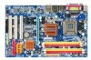
... the CPU 12 1-3-2 Installation of the Cooler 13 1-4 Installation of Memory 14 1-5 Installation of Expansion Cards 16 1-6 I/O Back Panel Introduction 17 1-7 Connectors Introduction 18 Chapter 2 BIOS Setup 29 The Main Menu (For example: GA-945PL-DS3 BIOS Ver.: F1a 30 2-1 Standard CMOS Features 32 2-2 Advanced BIOS Features 34 2-3 IntegratedPeripherals 36 2-4 Power Management Setup 39 2-5 PnP/PCI Configurations 41 2-6 PC Health Status 42 2-7 MB Intelligent Tweaker(M.I.T 44 2-8 Load Fail-Safe Defaults 47 2-9 Load Optimized Defaults 47 2-10 Set Supervisor/User Password...
... the CPU 12 1-3-2 Installation of the Cooler 13 1-4 Installation of Memory 14 1-5 Installation of Expansion Cards 16 1-6 I/O Back Panel Introduction 17 1-7 Connectors Introduction 18 Chapter 2 BIOS Setup 29 The Main Menu (For example: GA-945PL-DS3 BIOS Ver.: F1a 30 2-1 Standard CMOS Features 32 2-2 Advanced BIOS Features 34 2-3 IntegratedPeripherals 36 2-4 Power Management Setup 39 2-5 PnP/PCI Configurations 41 2-6 PC Health Status 42 2-7 MB Intelligent Tweaker(M.I.T 44 2-8 Load Fail-Safe Defaults 47 2-9 Load Optimized Defaults 47 2-10 Set Supervisor/User Password...
Manual
Page 10
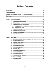
... connection of 4 SATA 3Gb/s devices O.S Support Š Microsoft Windows 2000/XP Memory Š 4 DDRII DIMM memory slots (supports up to 2 GB memory) Š Supports dual channel DDRII 533(Note 1)/400 DIMMs Š Supports 1.8V DDRII DIMMs Expanstion Slots Š 1 PCI Express x16 slot Š 3 PCI Express x1 slots Š 3 PCI slots Internal Connectors Š 1 24-pin ATX power connector Š 1 4-pin ATX 12V power connector Š 1 floppy connector Š 1 IDE connector Š 4 SATA 3Gb/s connectors Š 1 CPU fan connector Š 1 system fan connector Š 1 power...
... connection of 4 SATA 3Gb/s devices O.S Support Š Microsoft Windows 2000/XP Memory Š 4 DDRII DIMM memory slots (supports up to 2 GB memory) Š Supports dual channel DDRII 533(Note 1)/400 DIMMs Š Supports 1.8V DDRII DIMMs Expanstion Slots Š 1 PCI Express x16 slot Š 3 PCI Express x1 slots Š 3 PCI slots Internal Connectors Š 1 24-pin ATX power connector Š 1 4-pin ATX 12V power connector Š 1 floppy connector Š 1 IDE connector Š 4 SATA 3Gb/s connectors Š 1 CPU fan connector Š 1 system fan connector Š 1 power...
Manual
Page 11
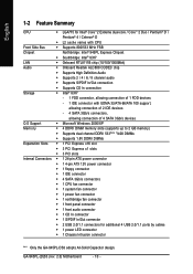
... mouse port Š 1 parallel port Š 1 serial port Š 4 USB 2.0/1.1 port Š 1 RJ-45 ports Š 6 audio jacks (Line In / Line Out / MIC In/Surround Speaker Out (Rear Speaker Out)/Center/Subwoofer Speaker Out/Side Speaker Out) I/O Control Š IT8718 chip Hardware Monitor Š System voltage detection Š CPU temperature detection Š CPU / Power / System fan speed detection Š CPU warning temperature Š CPU / Power / System fan failure warning Š Supports CPU Smart Fan function BIOS Š 1 4 Mbit flash ROM Š Use of licensed AWARD BIOS...
... mouse port Š 1 parallel port Š 1 serial port Š 4 USB 2.0/1.1 port Š 1 RJ-45 ports Š 6 audio jacks (Line In / Line Out / MIC In/Surround Speaker Out (Rear Speaker Out)/Center/Subwoofer Speaker Out/Side Speaker Out) I/O Control Š IT8718 chip Hardware Monitor Š System voltage detection Š CPU temperature detection Š CPU / Power / System fan speed detection Š CPU warning temperature Š CPU / Power / System fan failure warning Š Supports CPU Smart Fan function BIOS Š 1 4 Mbit flash ROM Š Use of licensed AWARD BIOS...
Manual
Page 13
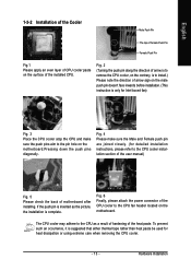
... using extreme care when removing the CPU cooler. - 13 - If the push pin is inserted as a result of hardening of arrow sign on the male push pin doesn't face inwards before installation. (This instruction is to the CPU cooler installation section of the user manual) Fig. 5 Please check the back of the installed CPU. Fig. 4 Please make sure the push pins aim to the CPU fan header located...
... using extreme care when removing the CPU cooler. - 13 - If the push pin is inserted as a result of hardening of arrow sign on the male push pin doesn't face inwards before installation. (This instruction is to the CPU cooler installation section of the user manual) Fig. 5 Please check the back of the installed CPU. Fig. 4 Please make sure the push pins aim to the CPU fan header located...
Manual
Page 15
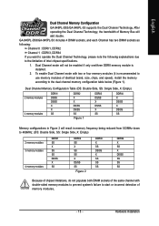
... (it is installed. 2. To enable Dual Channel mode with double-sided memory modules to prevent system's failure to start or incorrect detection of Intel chipset specifications. 1. English Dual Channel Memory Configuration GA-945PL-DS3/GA-945PL-S3 supports the Dual Channel Technology. GA-945PL-DS3/GA-945PL-S3 includes 4 DIMM sockets, and each Channel has two DIMM sockets as following: Channel 0 : DDRII1, DDRII2 Channel 1 : DDRII3, DDRII4 If you want to operate the Dual Channel Technology, please note the following explanations due to the dual channel memory configuration table below...
... (it is installed. 2. To enable Dual Channel mode with double-sided memory modules to prevent system's failure to start or incorrect detection of Intel chipset specifications. 1. English Dual Channel Memory Configuration GA-945PL-DS3/GA-945PL-S3 supports the Dual Channel Technology. GA-945PL-DS3/GA-945PL-S3 includes 4 DIMM sockets, and each Channel has two DIMM sockets as following: Channel 0 : DDRII1, DDRII2 Channel 1 : DDRII3, DDRII4 If you want to operate the Dual Channel Technology, please note the following explanations due to the dual channel memory configuration table below...
Manual
Page 20
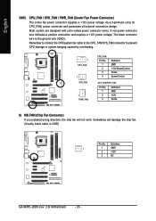
... NB_FAN (Chip Fan Connector) If you installed wrong direction, the chip fan will damage the chip fan. (Usually black cable is the ground wire (GND). The black connector wire is GND) Pin No. Sometimes will not work. A red power connector wire indicates a positive connection and requires a +12V power voltage. Definition 1 1 GND 2 +12V 3 NC GA-945PL-(D)S3 (rev. 2.0) Motherboard - 20 - English 3/4/5) CPU_FAN / SYS_FAN / PWR_FAN (Cooler Fan Power Connector) The cooler fan power connector supplies a +12V power voltage via a 3-pin/4-pin (only for CPU_FAN) power connector and...
... NB_FAN (Chip Fan Connector) If you installed wrong direction, the chip fan will damage the chip fan. (Usually black cable is the ground wire (GND). The black connector wire is GND) Pin No. Sometimes will not work. A red power connector wire indicates a positive connection and requires a +12V power voltage. Definition 1 1 GND 2 +12V 3 NC GA-945PL-(D)S3 (rev. 2.0) Motherboard - 20 - English 3/4/5) CPU_FAN / SYS_FAN / PWR_FAN (Cooler Fan Power Connector) The cooler fan power connector supplies a +12V power voltage via a 3-pin/4-pin (only for CPU_FAN) power connector and...
Manual
Page 21
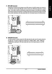
Hardware Installation English 7) IDE1 (IDE Connector) An IDE device connects to two IDE devices (hard drive or optical drive). Before attaching the FDD cable, please take note of the cable connects to connect two IDE devices, please set the jumper on the IDE device). If you wish to the FDD drive. The types of the foolproof groove in the IDE connector. 2 40 1 39 8) FDD (FDD Connector) The FDD connector is used to connect the FDD cable while the other as Master...
Hardware Installation English 7) IDE1 (IDE Connector) An IDE device connects to two IDE devices (hard drive or optical drive). Before attaching the FDD cable, please take note of the cable connects to connect two IDE devices, please set the jumper on the IDE device). If you wish to the FDD drive. The types of the foolproof groove in the IDE connector. 2 40 1 39 8) FDD (FDD Connector) The FDD connector is used to connect the FDD cable while the other as Master...
Manual
Page 22
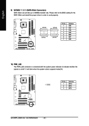
.... GA-945PL-(D)S3 (rev. 2.0) Motherboard - 22 - Pin No. It will blink when the system enters suspend mode(S1). Definition 1 1 MPD+ 2 MPD- 3 MPD- SATAII0 7 17 SATAII2 1 1 71 7 SATAII1 SATAII3 Pin No. 1 2 3 4 5 6 7 Definition GND TXP TXN GND RXN RXP GND 10) PWR_LED The PWR_LED connector is connected with the system power indicator to 300MB/s transfer rate. Please refer to the BIOS setting for the SATA...
.... GA-945PL-(D)S3 (rev. 2.0) Motherboard - 22 - Pin No. It will blink when the system enters suspend mode(S1). Definition 1 1 MPD+ 2 MPD- 3 MPD- SATAII0 7 17 SATAII2 1 1 71 7 SATAII1 SATAII3 Pin No. 1 2 3 4 5 6 7 Definition GND TXP TXN GND RXN RXP GND 10) PWR_LED The PWR_LED connector is connected with the system power indicator to 300MB/s transfer rate. Please refer to the BIOS setting for the SATA...
Manual
Page 24
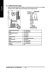
... (Power Switch) (Red) MSG (Message LED/Power/Sleep LED) (Yellow) NC ( Purple) Reset Switch IDE Hard Disk Active LED Pin 1: LED anode(+) Pin 2: LED cathode(-) Pin 1: Power Pin 2- Pin 3: NC Pin 4: Data(-) Open: Normal Close: Reset Hardware System Open: Normal Close: Power On/Off Pin 1: LED anode(+) Pin 2: LED cathode(-) NC GA-945PL-(D)S3 (rev. 2.0) Motherboard - 24 - Message LED/ Power/ Sleep LED Speaker Connector Power Switch MSG+ MSG- PW+ PWSPEAK+ SPEAK- 2 20 1 19 HD+ HD- English 12) F_PANEL (Front Panel Jumper) Please connect the power LED, PC speaker, reset switch and power...
... (Power Switch) (Red) MSG (Message LED/Power/Sleep LED) (Yellow) NC ( Purple) Reset Switch IDE Hard Disk Active LED Pin 1: LED anode(+) Pin 2: LED cathode(-) Pin 1: Power Pin 2- Pin 3: NC Pin 4: Data(-) Open: Normal Close: Reset Hardware System Open: Normal Close: Power On/Off Pin 1: LED anode(+) Pin 2: LED cathode(-) NC GA-945PL-(D)S3 (rev. 2.0) Motherboard - 24 - Message LED/ Power/ Sleep LED Speaker Connector Power Switch MSG+ MSG- PW+ PWSPEAK+ SPEAK- 2 20 1 19 HD+ HD- English 12) F_PANEL (Front Panel Jumper) Please connect the power LED, PC speaker, reset switch and power...

Manual
Page 32
... for faster system start up . You can use one of the two methods: Auto None Allows BIOS to automatically detect IDE/SATA devices during POST(default) None Select this to set the access mode for faster system start up . The time is 13:00:00. IDE Channel 0 Master IDE/SATA Device Setup. IDE Channel 0 Master, Slave IDE HDD Auto-Detection Press "Enter" to automatically detect IDE/SATA devices during POST(default) Select this option for automatic device detection. GA-945PL-(D)S3 (rev. 2.0) Motherboard - 32 - Week...
... for faster system start up . You can use one of the two methods: Auto None Allows BIOS to automatically detect IDE/SATA devices during POST(default) None Select this to set the access mode for faster system start up . The time is 13:00:00. IDE Channel 0 Master IDE/SATA Device Setup. IDE Channel 0 Master, Slave IDE HDD Auto-Detection Press "Enter" to automatically detect IDE/SATA devices during POST(default) Select this option for automatic device detection. GA-945PL-(D)S3 (rev. 2.0) Motherboard - 32 - Week...
Manual
Page 37
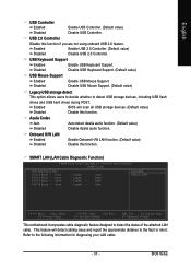
...Enter: Select F5: Previous Values +/-/PU/PD: Value F10: Save F6: Fail-Safe Defaults ESC: Exit F1: General Help F7: Optimized Defaults This motherboard incorporates cable diagnostic feature designed to the following information for diagnosing your LAN cable: - 37 - Disabled Disable USB Keyboard Support. (Default value) USB Mouse Support Enabled Enable USB Mouse Support. SMART LAN (LAN Cable Diagnostic Function) CMOS Setup Utility-Copyright (C) 1984-2006 Award Software SMART LAN Start detecting at Port..... Enabled Disabled Enable USB 2.0 Controller. (Default value) Disable USB...
...Enter: Select F5: Previous Values +/-/PU/PD: Value F10: Save F6: Fail-Safe Defaults ESC: Exit F1: General Help F7: Optimized Defaults This motherboard incorporates cable diagnostic feature designed to the following information for diagnosing your LAN cable: - 37 - Disabled Disable USB Keyboard Support. (Default value) USB Mouse Support Enabled Enable USB Mouse Support. SMART LAN (LAN Cable Diagnostic Function) CMOS Setup Utility-Copyright (C) 1984-2006 Award Software SMART LAN Start detecting at Port..... Enabled Disabled Enable USB 2.0 Controller. (Default value) Disable USB...
Manual
Page 42
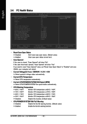
.... GA-945PL-(D)S3 (rev. 2.0) Motherboard - 42 - English 2-6 PC Health Status CMOS Setup Utility-Copyright (C) 1984-2006 Award Software PC Health Status Reset Case Open Status Case Opened Vcore DDR18V +3.3V +12V Current CPU Temperature Current CPU FAN Speed Current POWER FAN Speed Current SYSTEM FAN Speed CPU Warning Temperature CPU FAN Fail Warning POWER FAN Fail Warning SYSTEM FAN Fail Warning CPU Smart FAN Control CPU Smart FAN Mode [Disabled] No OK OK OK OK 47oC 3375 RPM 0 RPM 0 RPM [Disabled] [Disabled] [Disabled] [Disabled] [Enabled] [Auto] Item Help Menu Level` KLJI: Move Enter...
.... GA-945PL-(D)S3 (rev. 2.0) Motherboard - 42 - English 2-6 PC Health Status CMOS Setup Utility-Copyright (C) 1984-2006 Award Software PC Health Status Reset Case Open Status Case Opened Vcore DDR18V +3.3V +12V Current CPU Temperature Current CPU FAN Speed Current POWER FAN Speed Current SYSTEM FAN Speed CPU Warning Temperature CPU FAN Fail Warning POWER FAN Fail Warning SYSTEM FAN Fail Warning CPU Smart FAN Control CPU Smart FAN Mode [Disabled] No OK OK OK OK 47oC 3375 RPM 0 RPM 0 RPM [Disabled] [Disabled] [Disabled] [Disabled] [Enabled] [Auto] Item Help Menu Level` KLJI: Move Enter...
Manual
Page 48
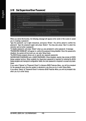
... the system is disabled, the system will boot and you can enter Setup freely. You will appear to confirm the password being disabled. Type the password again and press . English 2-10 Set Supervisor/User Password CMOS Setup Utility-Copyright (C) 1984-2006 Award Software ` Standard CMOS Features ` Advanced BIOS Features ` Integrated Peripherals ` Power Management Setup ` PnP/PCI ConfigurationEsnter Password: ` PC Health Status ` MB Intelligent Tweaker(M.I.T.) Load Fail-Safe Defaults Load Optimized Defaults Set Supervisor Password Set User Password Save & Exit Setup Exit Without Saving...
... the system is disabled, the system will boot and you can enter Setup freely. You will appear to confirm the password being disabled. Type the password again and press . English 2-10 Set Supervisor/User Password CMOS Setup Utility-Copyright (C) 1984-2006 Award Software ` Standard CMOS Features ` Advanced BIOS Features ` Integrated Peripherals ` Power Management Setup ` PnP/PCI ConfigurationEsnter Password: ` PC Health Status ` MB Intelligent Tweaker(M.I.T.) Load Fail-Safe Defaults Load Optimized Defaults Set Supervisor Password Set User Password Save & Exit Setup Exit Without Saving...
Manual
Page 49
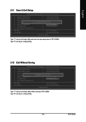
... Save & Exit Setup CMOS Setup Utility-Copyright (C) 1984-2006 Award Software ` Standard CMOS Features Load Fail-Safe Defaults ` Advanced BIOS Features Load Optimized Defaults ` Integrated Peripherals Set Supervisor Password ` Power Management Setup Save to CMOS and EXIT (SYe/tNU)?seYr Password ` PnP/PCI Configurations Save & Exit Setup ` PC Health Status Exit Without Saving ` MB Intelligent Tweaker(M.I .T.) ESC: Quit F8: Q-Flash Load Fail-Safe Defaults Load Optimized Defaults Set Supervisor Password Quit Without Saving (SYe/tNU)?sNer Password Save & Exit Setup Exit Without...
... Save & Exit Setup CMOS Setup Utility-Copyright (C) 1984-2006 Award Software ` Standard CMOS Features Load Fail-Safe Defaults ` Advanced BIOS Features Load Optimized Defaults ` Integrated Peripherals Set Supervisor Password ` Power Management Setup Save to CMOS and EXIT (SYe/tNU)?seYr Password ` PnP/PCI Configurations Save & Exit Setup ` PC Health Status Exit Without Saving ` MB Intelligent Tweaker(M.I .T.) ESC: Quit F8: Q-Flash Load Fail-Safe Defaults Load Optimized Defaults Set Supervisor Password Quit Without Saving (SYe/tNU)?sNer Password Save & Exit Setup Exit Without...
Manual
Page 51
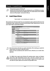
For USB2.0 driver support under "Device Manager". in "Universal Serial Bus controller" under Windows XP operating system, please use Windows Service Pack. If not, please double click the CD-ROM device icon in Windows XP. After install Windows Service Pack, it will auto start and show a question mark "?" English Chapter 3 Install Drivers Pictures below are shown in "My computer", and execute the Run.exe. 3-1 Install Chipset Drivers After insert the driver CD, "Xpress Install" will scan...
For USB2.0 driver support under "Device Manager". in "Universal Serial Bus controller" under Windows XP operating system, please use Windows Service Pack. If not, please double click the CD-ROM device icon in Windows XP. After install Windows Service Pack, it will auto start and show a question mark "?" English Chapter 3 Install Drivers Pictures below are shown in "My computer", and execute the Run.exe. 3-1 Install Chipset Drivers After insert the driver CD, "Xpress Install" will scan...
Manual
Page 56
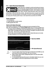
..., Award Software, Inc. System storage capacity and the reading/writing speed of the hard disk will appear in the bottom left corner of hard disk data. If you wish to run Xpress Recovery2 later, you can simply press F9 during system power-on PATA and SATA IDE controllers. VESA-supported VGA cards How to use the Xpress Recovery2 Initial access by booting from CD-ROM and subsequent access by booting from...
..., Award Software, Inc. System storage capacity and the reading/writing speed of the hard disk will appear in the bottom left corner of hard disk data. If you wish to run Xpress Recovery2 later, you can simply press F9 during system power-on PATA and SATA IDE controllers. VESA-supported VGA cards How to use the Xpress Recovery2 Initial access by booting from CD-ROM and subsequent access by booting from...
Manual
Page 59
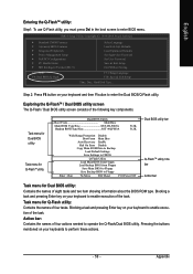
...: To use Q-Flash utility, you must press Del in the boot screen to enable execution of the following key components. CMOS Setup Utility-Copyright (C) 1984-2004 Award Software Standard CMOS Features Advanced BIOS Features Integrated Peripherals Power Management Setup PnP/PCI Configurations PC Health Status MB Intelligent Tweaker(M.I.T.) ESC: Quit F8: Dual BIOS/Q-Flash Select Language Load Fail-Safe Defaults Load Optimized Defaults Set Supervisor Password Set User Password Save & Exit Setup Exit Without Saving F3: Change Language F10: Save & Exit Setup Time, Date, Hard Disk Type...
...: To use Q-Flash utility, you must press Del in the boot screen to enable execution of the following key components. CMOS Setup Utility-Copyright (C) 1984-2004 Award Software Standard CMOS Features Advanced BIOS Features Integrated Peripherals Power Management Setup PnP/PCI Configurations PC Health Status MB Intelligent Tweaker(M.I.T.) ESC: Quit F8: Dual BIOS/Q-Flash Select Language Load Fail-Safe Defaults Load Optimized Defaults Set Supervisor Password Set User Password Save & Exit Setup Exit Without Saving F3: Change Language F10: Save & Exit Setup Time, Date, Hard Disk Type...
Manual
Page 61
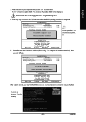
... Protection Disable Boot From Main Bios !A! The progress of updating BIOS will restart automatically after you are sure to exit the Q-Flash utility. Load Default Settings Save Settings to CMOS Q-Flash Utility Load Main BIOS from Floppy Load Backup BIOS from Floppy Save Main BIOS to Floppy Save Backup BIOS to Floppy Enter : Run :Move ESC:Reset F10:Power Off You can repeat Step 1 to 4 to flash the backup BIOS, too. 5. Please do not take out the floppy disk when it will begin to Floppy Enter...
... Protection Disable Boot From Main Bios !A! The progress of updating BIOS will restart automatically after you are sure to exit the Q-Flash utility. Load Default Settings Save Settings to CMOS Q-Flash Utility Load Main BIOS from Floppy Load Backup BIOS from Floppy Save Main BIOS to Floppy Save Backup BIOS to Floppy Enter : Run :Move ESC:Reset F10:Power Off You can repeat Step 1 to 4 to flash the backup BIOS, too. 5. Please do not take out the floppy disk when it will begin to Floppy Enter...
Manual
Page 62
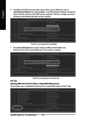
.... Part Two: Updating BIOS with Q-FlashTM Utility on your keyboard to save the settings to load BIOS Optimized Defaults. System will reboot after system reboots. GA-945PL-(D)S3 (rev. 2.0) Motherboard - 62 - Press Del to update BIOS using the Q-FlashTM utility. Normally the system redetects all devices after BIOS has been upgraded. CMOS Setup Utility-Copyright (C) 1984-2004 Award Software Standard CMOS Features Select Language Advanced BIOS Features Load Fail-Safe Defaults Integrated Peripherals Load Optimized Defaults Power Management Setup PnP/PCI Configurations...
.... Part Two: Updating BIOS with Q-FlashTM Utility on your keyboard to save the settings to load BIOS Optimized Defaults. System will reboot after system reboots. GA-945PL-(D)S3 (rev. 2.0) Motherboard - 62 - Press Del to update BIOS using the Q-FlashTM utility. Normally the system redetects all devices after BIOS has been upgraded. CMOS Setup Utility-Copyright (C) 1984-2004 Award Software Standard CMOS Features Select Language Advanced BIOS Features Load Fail-Safe Defaults Integrated Peripherals Load Optimized Defaults Power Management Setup PnP/PCI Configurations...
Manual
Page 72
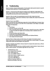
... get a weak sound after entering BIOS menu and you can use a metal object to MB again and turn on . Please press Ctrl and F1 keys after turning up . Re-insert the battery to enter BIOS and load Fail-Safe Defaults(or load Optimized Defaults). 7. AWARD BIOS Beep Codes 1 short: System boots successfully 2 short: CMOS setting error 1 long 1 short: DRAM or M/B error 1 long 2 short: Monitor or display card error 1 long 3 short: Keyboard error 1 long 9 short: BIOS ROM error Continuous long beeps: DRAM error Continuous short beeps: Power error GA-945PL-(D)S3 (rev. 2.0) Motherboard - 72...
... get a weak sound after entering BIOS menu and you can use a metal object to MB again and turn on . Please press Ctrl and F1 keys after turning up . Re-insert the battery to enter BIOS and load Fail-Safe Defaults(or load Optimized Defaults). 7. AWARD BIOS Beep Codes 1 short: System boots successfully 2 short: CMOS setting error 1 long 1 short: DRAM or M/B error 1 long 2 short: Monitor or display card error 1 long 3 short: Keyboard error 1 long 9 short: BIOS ROM error Continuous long beeps: DRAM error Continuous short beeps: Power error GA-945PL-(D)S3 (rev. 2.0) Motherboard - 72...


