Manual
Page 10
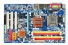
... Chipset Š Southbridge: Intel® ICH7 LAN Š Onboard RTL8111B chip (10/100/1000Mbit) Audio Š Onboard Realtek ALC888 CODEC chip Š Supports High Definition Audio Š Supports 2 / 4 / 6 / 8 channel audio Š Supports S/PDIF In/Out connection Š Supports CD In connection Storage Š Intel®... Š 2 USB 2.0/1.1 connectors for additional 4 USB 2.0/1.1 ports by cables Š 1 power LED connector Š 1 Chassis Intrusion connector "*" Only the GA-945PL-DS3 adopts All-Solid Capacitor design. GA-945PL-(D)S3 (rev. 2.0) Motherboard - 10 -
... Chipset Š Southbridge: Intel® ICH7 LAN Š Onboard RTL8111B chip (10/100/1000Mbit) Audio Š Onboard Realtek ALC888 CODEC chip Š Supports High Definition Audio Š Supports 2 / 4 / 6 / 8 channel audio Š Supports S/PDIF In/Out connection Š Supports CD In connection Storage Š Intel®... Š 2 USB 2.0/1.1 connectors for additional 4 USB 2.0/1.1 ports by cables Š 1 power LED connector Š 1 Chassis Intrusion connector "*" Only the GA-945PL-DS3 adopts All-Solid Capacitor design. GA-945PL-(D)S3 (rev. 2.0) Motherboard - 10 -
Manual
Page 19
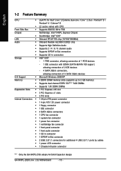
.... It is not connected, the system will not start . otherwise, please do not remove it. 3 4 1 2 ATX_12V Pin No. 1 2 3 4 Definition GND GND +12V +12V 12 24 1 13 ATX Pin No. 1 2 3 4 5 6 7 8 9 10 11 12 Definition 3.3V 3.3V GND +5V GND +5V GND Power Good 5V SB(stand by +5V) +12V +12V(Only for 24...-pin ATX) 3.3V(Only for 24-pin ATX) Pin No. 13 14 15 16 17 18 19 20 21 22 23 24 Definition 3.3V -12V GND PS_ON(soft On/Off) GND GND GND -5V +5V +5V +5V (Only for 24-pin ATX) GND(Only for 24-pin ATX...
.... It is not connected, the system will not start . otherwise, please do not remove it. 3 4 1 2 ATX_12V Pin No. 1 2 3 4 Definition GND GND +12V +12V 12 24 1 13 ATX Pin No. 1 2 3 4 5 6 7 8 9 10 11 12 Definition 3.3V 3.3V GND +5V GND +5V GND Power Good 5V SB(stand by +5V) +12V +12V(Only for 24...-pin ATX) 3.3V(Only for 24-pin ATX) Pin No. 13 14 15 16 17 18 19 20 21 22 23 24 Definition 3.3V -12V GND PS_ON(soft On/Off) GND GND GND -5V +5V +5V +5V (Only for 24-pin ATX) GND(Only for 24-pin ATX...
Manual
Page 20
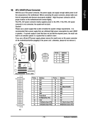
Sometimes will not work. A red power connector wire indicates a positive connection and requires a +12V power voltage. Definition 1 1 GND 2 +12V 3 NC GA-945PL-(D)S3 (rev. 2.0) Motherboard - 20 - Most coolers are designed with color-coded power connector wires. Remember to connect the CPU/system fan cable to the CPU_FAN/...
Sometimes will not work. A red power connector wire indicates a positive connection and requires a +12V power voltage. Definition 1 1 GND 2 +12V 3 NC GA-945PL-(D)S3 (rev. 2.0) Motherboard - 20 - Most coolers are designed with color-coded power connector wires. Remember to connect the CPU/system fan cable to the CPU_FAN/...
Manual
Page 22
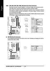
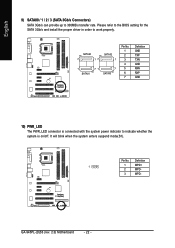
GA-945PL-(D)S3 (rev. 2.0) Motherboard - 22 - It will blink when the system enters suspend mode(S1). Pin No. SATAII0 7 17 SATAII2 1 1 71 7 SATAII1 SATAII3 Pin No. 1 2 3 4 5 6 7 Definition GND TXP TXN GND RXN RXP GND 10) PWR_LED The PWR_LED connector is on/off. Definition 1 1 MPD+ 2 MPD- 3 MPD- English 9) SATAII0 / 1 / 2 / 3 (SATA 3Gb/s Connectors) SATA 3Gb/s can provide...
GA-945PL-(D)S3 (rev. 2.0) Motherboard - 22 - It will blink when the system enters suspend mode(S1). Pin No. SATAII0 7 17 SATAII2 1 1 71 7 SATAII1 SATAII3 Pin No. 1 2 3 4 5 6 7 Definition GND TXP TXN GND RXN RXP GND 10) PWR_LED The PWR_LED connector is on/off. Definition 1 1 MPD+ 2 MPD- 3 MPD- English 9) SATAII0 / 1 / 2 / 3 (SATA 3Gb/s Connectors) SATA 3Gb/s can provide...
Manual
Page 23
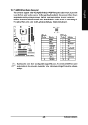
.... For optional front panel audio module, please contact your chassis manufacturer. 10 9 HD Audio: Pin No. 1 2 3 4 5 6 7 8 9 10 2 Definition MIC2_L GND MIC2_R -ACZ_DET LINE2_R FSENSE1 FAUDIO_JD No Pin LINE2_L FSENSE2 1 AC'97 Audio: Pin No. Definition 1 MIC 2 GND 3 MIC Power 4 NC 5 Line Out (R) 6 NC 7 NC 8 No Pin 9 Line Out (L) 10 NC By default...
.... For optional front panel audio module, please contact your chassis manufacturer. 10 9 HD Audio: Pin No. 1 2 3 4 5 6 7 8 9 10 2 Definition MIC2_L GND MIC2_R -ACZ_DET LINE2_R FSENSE1 FAUDIO_JD No Pin LINE2_L FSENSE2 1 AC'97 Audio: Pin No. Definition 1 MIC 2 GND 3 MIC Power 4 NC 5 Line Out (R) 6 NC 7 NC 8 No Pin 9 Line Out (L) 10 NC By default...
Manual
Page 25
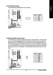
... (S/PDIF In/Out Connector) The S/PDIF output is capable of the SPDIF_IO connector. Use this feature only when your local dealer. 26 15 Pin No. 1 2 3 4 5 6 Definition Power No Pin SPDIF SPDIFI GND GND - 25 - For optional S/PDIF cable, please contact your stereo system has digital input function. Use S/PDIF IN feature...
... (S/PDIF In/Out Connector) The S/PDIF output is capable of the SPDIF_IO connector. Use this feature only when your local dealer. 26 15 Pin No. 1 2 3 4 5 6 Definition Power No Pin SPDIF SPDIFI GND GND - 25 - For optional S/PDIF cable, please contact your stereo system has digital input function. Use S/PDIF IN feature...
Manual
Page 26
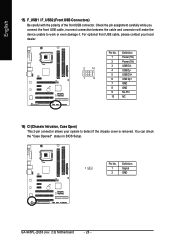
For optional front USB cable, please contact your local dealer. 2 10 1 9 Pin No. 1 2 3 4 5 6 7 8 9 10 Definition Power (5V) Power (5V) USB DXUSB DyUSB DX+ USB Dy+ GND GND No Pin NC 16) CI (Chassis Intrusion, Case Open) This 2-pin connector allows ... connect the front USB cable, incorrect connection between the cable and connector will make the device unable to detect if the chassis cover is removed. Definition 1 1 Signal 2 GND GA-945PL-(D)S3 (rev. 2.0) Motherboard - 26 -
For optional front USB cable, please contact your local dealer. 2 10 1 9 Pin No. 1 2 3 4 5 6 7 8 9 10 Definition Power (5V) Power (5V) USB DXUSB DyUSB DX+ USB Dy+ GND GND No Pin NC 16) CI (Chassis Intrusion, Case Open) This 2-pin connector allows ... connect the front USB cable, incorrect connection between the cable and connector will make the device unable to detect if the chassis cover is removed. Definition 1 1 Signal 2 GND GA-945PL-(D)S3 (rev. 2.0) Motherboard - 26 -
