
Manual
Page 8
Block Diagram PCIe CLK (100 MHz) LGA775 Processor CPU CLK+/-(200/133 MHz) PCI Express x16 RJ45 RTL 8111B x1 PCI Express Bus x1 x1 x1 PCIe CLK (100 MHz) 3 PCI Express x1 PCI Bus Host Interface Intel® 945PL DDRII 400/533 MHz DIMM Dual Channel Memory MCH CLK(200/133 MHz) BIOS 4 SATA 3Gb/s Intel® ATA33/66/100 ICH7 IDE1 Channel Floppy IT8718 LPT Port COM Port CODEC 8 USB Ports PS/2 KB/Mouse Surround Speaker Out Center/Subwoofer Speaker Out Side Speaker Out MIC Line-Out Line-In SPDIF In SPDIF Out 3 PCI PCI CLK (33 MHz) - 8 -
Block Diagram PCIe CLK (100 MHz) LGA775 Processor CPU CLK+/-(200/133 MHz) PCI Express x16 RJ45 RTL 8111B x1 PCI Express Bus x1 x1 x1 PCIe CLK (100 MHz) 3 PCI Express x1 PCI Bus Host Interface Intel® 945PL DDRII 400/533 MHz DIMM Dual Channel Memory MCH CLK(200/133 MHz) BIOS 4 SATA 3Gb/s Intel® ATA33/66/100 ICH7 IDE1 Channel Floppy IT8718 LPT Port COM Port CODEC 8 USB Ports PS/2 KB/Mouse Surround Speaker Out Center/Subwoofer Speaker Out Side Speaker Out MIC Line-Out Line-In SPDIF In SPDIF Out 3 PCI PCI CLK (33 MHz) - 8 -
Manual
Page 11
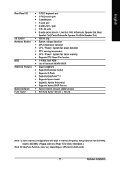
... I/O Š 1 PS/2 keyboard port Š 1 PS/2 mouse port Š 1 parallel port Š 1 serial port Š 4 USB 2.0/1.1 port Š 1 RJ-45 ports Š 6 audio jacks (Line In / Line Out / MIC In/Surround Speaker Out (Rear Speaker Out)/Center/Subwoofer Speaker Out/Side Speaker Out) I/O Control Š IT8718 chip Hardware Monitor Š System voltage...
... I/O Š 1 PS/2 keyboard port Š 1 PS/2 mouse port Š 1 parallel port Š 1 serial port Š 4 USB 2.0/1.1 port Š 1 RJ-45 ports Š 6 audio jacks (Line In / Line Out / MIC In/Surround Speaker Out (Rear Speaker Out)/Center/Subwoofer Speaker Out/Side Speaker Out) I/O Control Š IT8718 chip Hardware Monitor Š System voltage...
Manual
Page 17
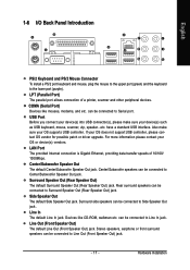
...Keyboard and PS/2 Mouse Connector To install a PS/2 port keyboard and mouse, plug the mouse to the upper port (green) and the keyboard to Line Out (Front Speaker Out) jack. - 17 - USB Port Before you connect your device(s) into USB connector(s), please make sure your device(s) such as... USB keyboard, mouse, scanner, zip, speaker...etc. Rear surround speakers can be connected to Center/Subwoofer Speaker Out jack. Line In The default Line In jack. LPT (Parallel Port) The parallel port allows connection of 10/100/ 1000Mbps. If your OS or device(s) vendors. Side ...
...Keyboard and PS/2 Mouse Connector To install a PS/2 port keyboard and mouse, plug the mouse to the upper port (green) and the keyboard to Line Out (Front Speaker Out) jack. - 17 - USB Port Before you connect your device(s) into USB connector(s), please make sure your device(s) such as... USB keyboard, mouse, scanner, zip, speaker...etc. Rear surround speakers can be connected to Center/Subwoofer Speaker Out jack. Line In The default Line In jack. LPT (Parallel Port) The parallel port allows connection of 10/100/ 1000Mbps. If your OS or device(s) vendors. Side ...
Manual
Page 23
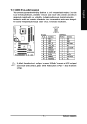
Definition 1 MIC 2 GND 3 MIC Power 4 NC 5 Line Out (R) 6 NC 7 NC 8 No Pin 9 Line Out (L) 10 NC By default, the audio driver is configured to this connector, please refer to work or even damage it. English 11) F_AUDIO (Front ...
Definition 1 MIC 2 GND 3 MIC Power 4 NC 5 Line Out (R) 6 NC 7 NC 8 No Pin 9 Line Out (L) 10 NC By default, the audio driver is configured to this connector, please refer to work or even damage it. English 11) F_AUDIO (Front ...
Manual
Page 29
Status Page Setup Menu / Option Page Setup Menu Press F1 to use and the possible selections for Main Menu Main Menu The on-line description of the highlighted setup function is displayed at the bottom of the motherboard. To exit the Help Window press . English Chapter 2 BIOS ... the power is potentially risky, please do it with caution and avoid inadequate operation that does not require users to boot to a new BIOS, either Gigabyte's Q-Flash or @BIOS utility can enter the BIOS setup screen by pressing "Ctrl + F1". BIOS Setup Because BIOS flashing is turned off, the...
Status Page Setup Menu / Option Page Setup Menu Press F1 to use and the possible selections for Main Menu Main Menu The on-line description of the highlighted setup function is displayed at the bottom of the motherboard. To exit the Help Window press . English Chapter 2 BIOS ... the power is potentially risky, please do it with caution and avoid inadequate operation that does not require users to boot to a new BIOS, either Gigabyte's Q-Flash or @BIOS utility can enter the BIOS setup screen by pressing "Ctrl + F1". BIOS Setup Because BIOS flashing is turned off, the...
Manual
Page 67
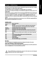
... Manager icon in your system tray (you can also find the icon in Windows XP) Center/Subwoofer Speaker Out Rear Speaker Out Side Speaker Out Line In Line Out (Front Speaker Out) Mic In Note that support audio output at the same time. English 4-1-4 2- / 4- / 6- / 8- Doubleclick the icon to 192 kHz/24-bit...
... Manager icon in your system tray (you can also find the icon in Windows XP) Center/Subwoofer Speaker Out Rear Speaker Out Side Speaker Out Line In Line Out (Front Speaker Out) Mic In Note that support audio output at the same time. English 4-1-4 2- / 4- / 6- / 8- Doubleclick the icon to 192 kHz/24-bit...

Manual
Page 68
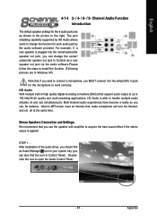
The 2-channel audio setup is completed. 4 Channel Audio Setup STEP 1 : After installation of equipment is plugged into the rear Line Out jack, a small window will pop up and ask you what type of the audio driver, you should find an Audio Manager icon in ... Control Panel, click the Audio I /O tab. In the upper left list, click 4CH Speaker. Choose Headphone or Line Out depending on the device connected and click OK. In the upper left list, click 2CH Speaker. GA-945PL-(D)S3 (rev. 2.0) Motherboard - 68 - English STEP 2: In the Audio Control Panel, click the Audio I /O tab. ...
The 2-channel audio setup is completed. 4 Channel Audio Setup STEP 1 : After installation of equipment is plugged into the rear Line Out jack, a small window will pop up and ask you what type of the audio driver, you should find an Audio Manager icon in ... Control Panel, click the Audio I /O tab. In the upper left list, click 4CH Speaker. Choose Headphone or Line Out depending on the device connected and click OK. In the upper left list, click 2CH Speaker. GA-945PL-(D)S3 (rev. 2.0) Motherboard - 68 - English STEP 2: In the Audio Control Panel, click the Audio I /O tab. ...
Manual
Page 69
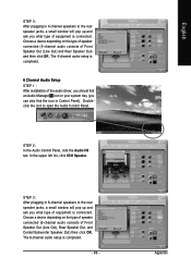
...can also find the icon in Control Panel). Choose a device depending on the type of speaker connected (4-channel audio consists of Front Speaker Out (Line Out) and Rear Speaker Out) and then click OK. In the upper left list, click 6CH Speaker. STEP 3: After plugging in 6-channel ...ask you what type of equipment is connected. Choose a device depending on the type of speaker connected (6-channel audio consists of Front Speaker Out (Line Out), Rear Speaker Out, and Center/Subwoofer Speaker Out) then click OK. Doubleclick the icon to open the Audio Control Panel. Appendix English ...
...can also find the icon in Control Panel). Choose a device depending on the type of speaker connected (4-channel audio consists of Front Speaker Out (Line Out) and Rear Speaker Out) and then click OK. In the upper left list, click 6CH Speaker. STEP 3: After plugging in 6-channel ...ask you what type of equipment is connected. Choose a device depending on the type of speaker connected (6-channel audio consists of Front Speaker Out (Line Out), Rear Speaker Out, and Center/Subwoofer Speaker Out) then click OK. Doubleclick the icon to open the Audio Control Panel. Appendix English ...
Manual
Page 70
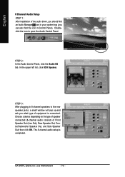
... find the icon in your system tray (you what type of Front Speaker Out (Line Out), Rear Speaker Out, Center/Subwoofer Speaker Out, and Side Speaker Out) then click OK. In the upper left list, click 8CH Speaker. GA-945PL-(D)S3 (rev. 2.0) Motherboard - 70 - STEP 2: In the Audio Control Panel, click the Audio...
... find the icon in your system tray (you what type of Front Speaker Out (Line Out), Rear Speaker Out, Center/Subwoofer Speaker Out, and Side Speaker Out) then click OK. In the upper left list, click 8CH Speaker. GA-945PL-(D)S3 (rev. 2.0) Motherboard - 70 - STEP 2: In the Audio Control Panel, click the Audio...

