Manual
Page 5
... of the CPU 14 1-3-2 Installation of the CPU Cooler 15 1-4 Installation of Memory 16 1-5 Installation of Expansion Cards 18 1-6 I/O Back Panel Introduction 19 1-7 Connectors Introduction 20 Chapter 2 BIOS Setup 31 The Main Menu (For example: GA-945GCMX-S2 BIOS Ver. : F5a 32 2-1 Standard CMOS Features 34 2-2 Advanced BIOS Features 36 2-3 IntegratedPeripherals 38 2-4 Power Management Setup 42 2-5 PnP/PCI Configurations 44 2-6 PC Health Status 45 2-7 Frequency/Voltage Control 47 2-8 Load Fail-Safe Defaults 49 2-9 Load Optimized Defaults 49 2-10 Set Supervisor/User Password 50...
... of the CPU 14 1-3-2 Installation of the CPU Cooler 15 1-4 Installation of Memory 16 1-5 Installation of Expansion Cards 18 1-6 I/O Back Panel Introduction 19 1-7 Connectors Introduction 20 Chapter 2 BIOS Setup 31 The Main Menu (For example: GA-945GCMX-S2 BIOS Ver. : F5a 32 2-1 Standard CMOS Features 34 2-2 Advanced BIOS Features 36 2-3 IntegratedPeripherals 38 2-4 Power Management Setup 42 2-5 PnP/PCI Configurations 44 2-6 PC Health Status 45 2-7 Frequency/Voltage Control 47 2-8 Load Fail-Safe Defaults 49 2-9 Load Optimized Defaults 49 2-10 Set Supervisor/User Password 50...
Manual
Page 10
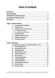
... LAN CODEC 3 PCI 2 PCI PCI CLK PCI CLK (33 MHz) (33 MHz) ATA-33/66/100 IDE Channel BIOS 4 SATA 3Gb/s 8 USB Ports IT8718 Floppy LPT Port COM Ports PS/2 KB/Mouse Surround Speaker Out Center/Subwoofer Speaker Out Side Speaker Out MIC Line-Out Line-In SPDIF In SPDIF Out (Note 1) Enable use of a 1066/800 MHz FSB CPU is required if you wish to install DDR2 667 MHz memory. Only for GA-945GCMX-S2...
... LAN CODEC 3 PCI 2 PCI PCI CLK PCI CLK (33 MHz) (33 MHz) ATA-33/66/100 IDE Channel BIOS 4 SATA 3Gb/s 8 USB Ports IT8718 Floppy LPT Port COM Ports PS/2 KB/Mouse Surround Speaker Out Center/Subwoofer Speaker Out Side Speaker Out MIC Line-Out Line-In SPDIF In SPDIF Out (Note 1) Enable use of a 1066/800 MHz FSB CPU is required if you wish to install DDR2 667 MHz memory. Only for GA-945GCMX-S2...
Manual
Page 12
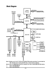
...138; 2 PCI slots Š 3 PCI slots Internal Connectors Š 1 24-pin ATX power connector Š 1 4-pin ATX 12V power connector Š 1 floppy connector Š 1 IDE connector Š 4 SATA 3Gb/s connectors Š 1 CPU fan connector Š 1 system fan connector Š 1 front panel connector Š 1 front audio connector Š 1 CD In connector Š 1 S/PDIF In/Out connector Š 2 USB 2.0/1.1 connectors for additional 4 ports by cables Š 1 COMB connector Š 1 Chassis Intrusion connector Š 1 power LED connector Only for GA-945GCM-S2. Only for GA...
...138; 2 PCI slots Š 3 PCI slots Internal Connectors Š 1 24-pin ATX power connector Š 1 4-pin ATX 12V power connector Š 1 floppy connector Š 1 IDE connector Š 4 SATA 3Gb/s connectors Š 1 CPU fan connector Š 1 system fan connector Š 1 front panel connector Š 1 front audio connector Š 1 CD In connector Š 1 S/PDIF In/Out connector Š 2 USB 2.0/1.1 connectors for additional 4 ports by cables Š 1 COMB connector Š 1 Chassis Intrusion connector Š 1 power LED connector Only for GA-945GCM-S2. Only for GA...
Manual
Page 15
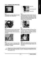
... the motherboard.Pressing down the push pins diagonally. Hardware Installation Fig. 6 Finally, please attach the power connector of motherboard after installing. Fig. 4 Please make sure the Male and Female push pin are joined closely. (for Intel boxed fan) Fig. 3 Place the CPU cooler atop the CPU and make sure the push pins aim to the CPU fan header located on the motherboard. Use extreme care when removing the CPU cooler...
... the motherboard.Pressing down the push pins diagonally. Hardware Installation Fig. 6 Finally, please attach the power connector of motherboard after installing. Fig. 4 Please make sure the Male and Female push pin are joined closely. (for Intel boxed fan) Fig. 3 Place the CPU cooler atop the CPU and make sure the push pins aim to the CPU fan header located on the motherboard. Use extreme care when removing the CPU cooler...

Manual
Page 17
The GA-945GCMX-S2/GA-945GCM-S2 includes 2 DIMM sockets. English Dual Channel Memory Configuration The GA-945GCMX-S2/GA-945GCM-S2 supports the Dual Channel Technology. If you want to operate the Dual Channel Technology, please note the following explanations due to the limitation of memory bus will not be used. - 17 - Hardware Installation Dual Channel mode will double. When enabling Dual Channel mode with two memory modules, it is recommended that memory of the same capacity, brand, speed, and chips be enabled if only one DDR2 memory module...
The GA-945GCMX-S2/GA-945GCM-S2 includes 2 DIMM sockets. English Dual Channel Memory Configuration The GA-945GCMX-S2/GA-945GCM-S2 supports the Dual Channel Technology. If you want to operate the Dual Channel Technology, please note the following explanations due to the limitation of memory bus will not be used. - 17 - Hardware Installation Dual Channel mode will double. When enabling Dual Channel mode with two memory modules, it is recommended that memory of the same capacity, brand, speed, and chips be enabled if only one DDR2 memory module...

Manual
Page 22
... KB, 1.2 MB, 1.44 MB and 2.88 MB. A red power connector wire indicates a positive connection and requires a +12V power voltage. Before attaching the FDD cable, please take note of FDD drives supported are designed with color-coded power connector wires. English 3/4) CPU_FAN / SYS_FAN (Cooler Fan Power Connector) The cooler fan power connector supplies a +12V power voltage via a 3-pin/4-pin(CPU_FAN) power connector and possesses a foolproof connection design. The types of the foolproof groove in the FDD connector. 34 33 2 1 GA-945GCM(X)-S2 Motherboard - 22 -
... KB, 1.2 MB, 1.44 MB and 2.88 MB. A red power connector wire indicates a positive connection and requires a +12V power voltage. Before attaching the FDD cable, please take note of FDD drives supported are designed with color-coded power connector wires. English 3/4) CPU_FAN / SYS_FAN (Cooler Fan Power Connector) The cooler fan power connector supplies a +12V power voltage via a 3-pin/4-pin(CPU_FAN) power connector and possesses a foolproof connection design. The types of the foolproof groove in the FDD connector. 34 33 2 1 GA-945GCM(X)-S2 Motherboard - 22 -

Manual
Page 23
... BIOS setting for information on settings, please refer to two IDE devices (hard drive or optical drive). English 6) IDE (IDE Connector) An IDE device connects to work properly. 1 SATAII2 7 1 SATAII0 7 7 SATAII3 1 7 SATAII1 1 Pin No. 1 2 3 4 5 6 7 Definition GND TXP TXN GND RXN RXP GND - 23 - One IDE connector can connect to one IDE device as Master and the other as Slave (for the SATA 3Gb/s and install the proper driver in the IDE connector. 40 39 2 1 7) SATAII0 / 1 / 2 / 3 (SATA 3Gb/s Connector, Controlled...
... BIOS setting for information on settings, please refer to two IDE devices (hard drive or optical drive). English 6) IDE (IDE Connector) An IDE device connects to work properly. 1 SATAII2 7 1 SATAII0 7 7 SATAII3 1 7 SATAII1 1 Pin No. 1 2 3 4 5 6 7 Definition GND TXP TXN GND RXN RXP GND - 23 - One IDE connector can connect to one IDE device as Master and the other as Slave (for the SATA 3Gb/s and install the proper driver in the IDE connector. 40 39 2 1 7) SATAII0 / 1 / 2 / 3 (SATA 3Gb/s Connector, Controlled...

Manual
Page 26
... use the front audio function, connect the front panel audio module to support HD Audio. Pin No. If you connect the front panel audio module. For optional front panel audio module, please contact your chassis manufacturer. 10 9 HD Audio: Pin No. 1 2 3 4 5 6 7 8 9 10 2 Definition MIC2_L GND MIC2_R -ACZ_DET LINE2_R FSENSE1 FAUDIO_JD No Pin LINE2_L FSENSE2 1 AC'97 Audio: Pin No. Definition 1 CD-L 1 2 GND 3 GND 4 CD-R GA-945GCM(X)-S2 Motherboard - 26 - English 11) F_AUDIO (Front Audio Connector) This connector supports...
... use the front audio function, connect the front panel audio module to support HD Audio. Pin No. If you connect the front panel audio module. For optional front panel audio module, please contact your chassis manufacturer. 10 9 HD Audio: Pin No. 1 2 3 4 5 6 7 8 9 10 2 Definition MIC2_L GND MIC2_R -ACZ_DET LINE2_R FSENSE1 FAUDIO_JD No Pin LINE2_L FSENSE2 1 AC'97 Audio: Pin No. Definition 1 CD-L 1 2 GND 3 GND 4 CD-R GA-945GCM(X)-S2 Motherboard - 26 - English 11) F_AUDIO (Front Audio Connector) This connector supports...
Manual
Page 32
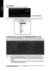
...) will appear on cards) device. English : Boot Menu Select boot sequence for your motherboard. CMOS Setup Utility-Copyright (C) 1984-2007 Award Software ` Standard CMOS Features ` Advanced BIOS Features ` Integrated Peripherals ` Power Management Setup ` PnP/PCI Configurations ` PC Health Status ` Frequency/Voltage Control ESC: Quit F8: Q-Flash Load Fail-Safe Defaults Load Optimized Defaults Set Supervisor Password Set User Password Save & Exit Setup Exit Without Saving KLJI: Select Item F10: Save & Exit Setup Time, Date, Hard Disk Type... 1. GA-945GCM(X)-S2 Motherboard - 32 - If...
...) will appear on cards) device. English : Boot Menu Select boot sequence for your motherboard. CMOS Setup Utility-Copyright (C) 1984-2007 Award Software ` Standard CMOS Features ` Advanced BIOS Features ` Integrated Peripherals ` Power Management Setup ` PnP/PCI Configurations ` PC Health Status ` Frequency/Voltage Control ESC: Quit F8: Q-Flash Load Fail-Safe Defaults Load Optimized Defaults Set Supervisor Password Set User Password Save & Exit Setup Exit Without Saving KLJI: Select Item F10: Save & Exit Setup Time, Date, Hard Disk Type... 1. GA-945GCM(X)-S2 Motherboard - 32 - If...
Manual
Page 34
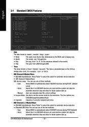
... Keyboard] Base Memory Extended Memory 640K 239M KLJI: Move Enter: Select F5: Previous Values +/-/PU/PD: Value F10: Save F6: Fail-Safe Defaults ESC: Exit F1: General Help F7: Optimized Defaults Date The date format is calculated base on the 24-hour military-time clock. For example, 1 p.m. You can manually input the correct settings. Extended IDE Drive You can use one of currectly installed hard drive. GA-945GCM(X)-S2 Motherboard...
... Keyboard] Base Memory Extended Memory 640K 239M KLJI: Move Enter: Select F5: Previous Values +/-/PU/PD: Value F10: Save F6: Fail-Safe Defaults ESC: Exit F1: General Help F7: Optimized Defaults Date The date format is calculated base on the 24-hour military-time clock. For example, 1 p.m. You can manually input the correct settings. Extended IDE Drive You can use one of currectly installed hard drive. GA-945GCM(X)-S2 Motherboard...

Manual
Page 37
... monitor utility is only working for operating system with multi processors mode supported. (Default value) Disabled Disable CPU Hyper Threading. Virtualization Technology (Note) Enabled Disabled Enable Virtualization technology function. (Default value) Disable this function. (Note) This item will show up when you install a processor which supports this feature is installed. Disabled Disable HDD S.M.A.R.T. Init Display First Specifies the first initiation of the monitor display from the installed PCI graphics card, PCI Express graphics card, or the onboard VGA. CPU...
... monitor utility is only working for operating system with multi processors mode supported. (Default value) Disabled Disable CPU Hyper Threading. Virtualization Technology (Note) Enabled Disabled Enable Virtualization technology function. (Default value) Disable this function. (Note) This item will show up when you install a processor which supports this feature is installed. Disabled Disable HDD S.M.A.R.T. Init Display First Specifies the first initiation of the monitor display from the installed PCI graphics card, PCI Express graphics card, or the onboard VGA. CPU...

Manual
Page 39
... onboard USB 2.0 feature. Enabled BIOS will scan all USB storage devices. (Default value) Disabled Disable this function. Azalia Codec Auto Disabled Auto detect Azalia audio function. (Default value) Disable Azalia audio function. USB Keyboard Support Enabled Disabled Enable USB keyboard support. Enabled Disabled Enable USB 2.0 controller. (Default value) Disable USB 2.0 controller. Disabled Disable USB mouse support. (Default value) Legacy USB storage detect This option allows users to decide whether to detect USB storage devices, including USB flash drives and USB hard...
... onboard USB 2.0 feature. Enabled BIOS will scan all USB storage devices. (Default value) Disabled Disable this function. Azalia Codec Auto Disabled Auto detect Azalia audio function. (Default value) Disable Azalia audio function. USB Keyboard Support Enabled Disabled Enable USB keyboard support. Enabled Disabled Enable USB 2.0 controller. (Default value) Disable USB 2.0 controller. Disabled Disable USB mouse support. (Default value) Legacy USB storage detect This option allows users to decide whether to detect USB storage devices, including USB flash drives and USB hard...
Manual
Page 44
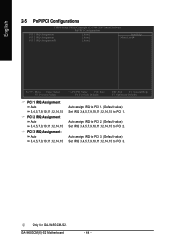
GA-945GCM(X)-S2 Motherboard - 44 - Only for GA-945GCM-S2. Auto assign IRQ to PCI 3. (Default value) Set IRQ 3,4,5,7,9,10,11,12,14,15 to PCI 1. English 2-5 PnP/PCI Configurations CMOS Setup Utility-Copyright (C) 1984-2007 Award Software PnP/PCI Configurations PCI 1 IRQ Assignment PCI 2 IRQ Assignment PCI 3 IRQ Assignment2 [Auto] [Auto] [Auto] Item Help Menu Level` KLJI: Move Enter: Select F5: Previous Values PCI 1 IRQ Assignment Auto 3,4,5,7,9,10,11,12,14,15 PCI 2 IRQ Assignment Auto 3,4,5,7,9,10,11,12,14,15 PCI 3 IRQ Assignment...
GA-945GCM(X)-S2 Motherboard - 44 - Only for GA-945GCM-S2. Auto assign IRQ to PCI 3. (Default value) Set IRQ 3,4,5,7,9,10,11,12,14,15 to PCI 1. English 2-5 PnP/PCI Configurations CMOS Setup Utility-Copyright (C) 1984-2007 Award Software PnP/PCI Configurations PCI 1 IRQ Assignment PCI 2 IRQ Assignment PCI 3 IRQ Assignment2 [Auto] [Auto] [Auto] Item Help Menu Level` KLJI: Move Enter: Select F5: Previous Values PCI 1 IRQ Assignment Auto 3,4,5,7,9,10,11,12,14,15 PCI 2 IRQ Assignment Auto 3,4,5,7,9,10,11,12,14,15 PCI 3 IRQ Assignment...

Manual
Page 47
.... For power End-User use only! (Note) This item will show up when you use a 533 MHz FSB processor, set "CPU Host Frequency" to 266 MHz. BIOS Setup The option will automatically assign by CPU detection. If you use of a CoreTM 2 CPU with DDR2 533 (or above) memory module(s). for GA-945GCMX-S2. - 47 - Disabled Disable CPU Host Clock Control. (Default value) Enabled Enable CPU Host Clock Control. Incorrect using these components. English 2-7 Frequency/Voltage Control CMOS Setup Utility-Copyright (C) 1984-2007 Award Software Frequency/Voltage Control CPU Clock Ratio...
.... For power End-User use only! (Note) This item will show up when you use a 533 MHz FSB processor, set "CPU Host Frequency" to 266 MHz. BIOS Setup The option will automatically assign by CPU detection. If you use of a CoreTM 2 CPU with DDR2 533 (or above) memory module(s). for GA-945GCMX-S2. - 47 - Disabled Disable CPU Host Clock Control. (Default value) Enabled Enable CPU Host Clock Control. Incorrect using these components. English 2-7 Frequency/Voltage Control CMOS Setup Utility-Copyright (C) 1984-2007 Award Software Frequency/Voltage Control CPU Clock Ratio...
Manual
Page 50
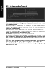
... the center of the screen to assist you in creating a password. English 2-10 Set Supervisor/User Password CMOS Setup Utility-Copyright (C) 1984-2007 Award Software ` Standard CMOS Features ` Advanced BIOS Features ` Integrated Peripherals ` Power Management Setup ` PnP/PCI ConfiguratioEnsnter Password: ` PC Health Status ` Frequency/Voltage Control Load Fail-Safe Defaults Load Optimized Defaults Set Supervisor Password Set User Password Save & Exit Setup Exit Without Saving ESC: Quit F8: Q-Flash KLJI: Select Item F10: Save & Exit Setup Change/Set/Disable Password When you select this...
... the center of the screen to assist you in creating a password. English 2-10 Set Supervisor/User Password CMOS Setup Utility-Copyright (C) 1984-2007 Award Software ` Standard CMOS Features ` Advanced BIOS Features ` Integrated Peripherals ` Power Management Setup ` PnP/PCI ConfiguratioEnsnter Password: ` PC Health Status ` Frequency/Voltage Control Load Fail-Safe Defaults Load Optimized Defaults Set Supervisor Password Set User Password Save & Exit Setup Exit Without Saving ESC: Quit F8: Q-Flash KLJI: Select Item F10: Save & Exit Setup Change/Set/Disable Password When you select this...
Manual
Page 53
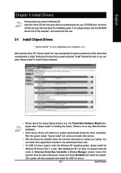
... device drivers will restart your CD-ROM drive, the driver CD-title will auto start and show the installation guide. Please pick the item that came with your motherboard into your system automatically during the driver installation. Insert the driver CD-title that you can install other drivers. • After the drivers are shown in the motherboard driver disk. • For USB 2.0 driver support under the Windows XP operating system, please install the Windows XP Service...
... device drivers will restart your CD-ROM drive, the driver CD-title will auto start and show the installation guide. Please pick the item that came with your motherboard into your system automatically during the driver installation. Insert the driver CD-title that you can install other drivers. • After the drivers are shown in the motherboard driver disk. • For USB 2.0 driver support under the Windows XP operating system, please install the Windows XP Service...
Manual
Page 58
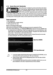
... SATA IDE controllers. Intel x86 platforms 2. Insert the provided driver CD into your hard disk. VESA-supported VGA cards How to startup XpressRecovery2..... Boot from CD/DVD:" will affect the data backup speed. 3. Upon system restart, the message which says "Boot from CD/DVD: Press any key to provide quick backup and restoration of system memory 3. Award Modular BIOS v6.00PG, An Energy Star Ally Copyright (C) 1984-2007, Award Software...
... SATA IDE controllers. Intel x86 platforms 2. Insert the provided driver CD into your hard disk. VESA-supported VGA cards How to startup XpressRecovery2..... Boot from CD/DVD:" will affect the data backup speed. 3. Upon system restart, the message which says "Boot from CD/DVD: Press any key to provide quick backup and restoration of system memory 3. Award Modular BIOS v6.00PG, An Energy Star Ally Copyright (C) 1984-2007, Award Software...
Manual
Page 60
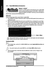
... Use: Follow the steps below before using FAT32/16/12 file system. 3. Extract the downloaded BIOS files and save the new BIOS file (e.g. 9gcmxs2.F1) to the independent IDE/SATA controller. NOTE: Press the End key to enter Q-Flash if you wish to back up the current BIOS file, use the UP or DOWN ARROW key to select Update BIOS from Drive Sa0vefilBeI(Os)SfotounDdrive EnteFr l:oRppuyn A :Move ESC:Reset :Power Off HDD 0-0 Total size : 0 GA-945GCM(X)-S2 Motherboard Free size...
... Use: Follow the steps below before using FAT32/16/12 file system. 3. Extract the downloaded BIOS files and save the new BIOS file (e.g. 9gcmxs2.F1) to the independent IDE/SATA controller. NOTE: Press the End key to enter Q-Flash if you wish to back up the current BIOS file, use the UP or DOWN ARROW key to select Update BIOS from Drive Sa0vefilBeI(Os)SfotounDdrive EnteFr l:oRppuyn A :Move ESC:Reset :Power Off HDD 0-0 Total size : 0 GA-945GCM(X)-S2 Motherboard Free size...
Manual
Page 62
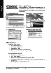
... update process following the instruction. Click "Internet Update" icon b. Select the exact model name on your motherboard e. Please search for BIOS unzip file, downloading from internet or any other methods (such as: 9gcmxs2.F1). The @BIOS Utility Fig 4. Select @BIOSTM sever d. Just select the desired @BIOS server to update their BIOS under Windows. Installation Complete and Run @BIOS Click Start/ Programs/ GIGABYTE/@BIOS/@BIOS Select @BIOS item than click Install Fig 3. e. d. Installing the @BIOS utility...
... update process following the instruction. Click "Internet Update" icon b. Select the exact model name on your motherboard e. Please search for BIOS unzip file, downloading from internet or any other methods (such as: 9gcmxs2.F1). The @BIOS Utility Fig 4. Select @BIOSTM sever d. Just select the desired @BIOS server to update their BIOS under Windows. Installation Complete and Run @BIOS Click Start/ Programs/ GIGABYTE/@BIOS/@BIOS Select @BIOS item than click Install Fig 3. e. d. Installing the @BIOS utility...
Manual
Page 69
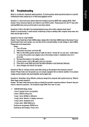
...CMOS setting error 1 long 1 short: DRAM or M/B error 1 long 2 short: Monitor or display card error 1 long 3 short: Keyboard error 1 long 9 short: BIOS ROM error Continuous long beeps: DRAM error Continuous short beeps: Power error - 69 - Appendix Turn off the on-board battery to leak voltage to clear CMOS. If not, please change another speaker with an internal amplifier. What do these options. Question 3: How do I clear CMOS? If your board has a Clear CMOS jumper, please refer to makethem short for reference purposes. Disconnect the power cord from case to case. Connect...
...CMOS setting error 1 long 1 short: DRAM or M/B error 1 long 2 short: Monitor or display card error 1 long 3 short: Keyboard error 1 long 9 short: BIOS ROM error Continuous long beeps: DRAM error Continuous short beeps: Power error - 69 - Appendix Turn off the on-board battery to leak voltage to clear CMOS. If not, please change another speaker with an internal amplifier. What do these options. Question 3: How do I clear CMOS? If your board has a Clear CMOS jumper, please refer to makethem short for reference purposes. Disconnect the power cord from case to case. Connect...


