Manual
Page 4
... Heatsink 12 1-3-1 Installation of the CPU 12 1-3-2 Installation of the Heatsink 13 1-4 Installation of Memory 14 1-5 Install expansion cards 16 1-6 I/O Back Panel Introduction 17 1-7 Connectors Introduction 18 Chapter 2 BIOS Setup 29 The Main Menu (For example: BIOS Ver. : F2 30 2-1 Standard CMOS Features 32 2-2 Advanced BIOS Features 35 2-3 IntegratedPeripherals 37 2-4 Power Management Setup 40 2-5 PnP/PCI Configurations 42 2-6 PC Health Status 43 2-7 Frequency/Voltage Control 45 2-8 Load Fail-Safe Defaults 46 2-9 Load Optimized Defaults 46 2-10 Set Supervisor/User Password...
... Heatsink 12 1-3-1 Installation of the CPU 12 1-3-2 Installation of the Heatsink 13 1-4 Installation of Memory 14 1-5 Install expansion cards 16 1-6 I/O Back Panel Introduction 17 1-7 Connectors Introduction 18 Chapter 2 BIOS Setup 29 The Main Menu (For example: BIOS Ver. : F2 30 2-1 Standard CMOS Features 32 2-2 Advanced BIOS Features 35 2-3 IntegratedPeripherals 37 2-4 Power Management Setup 40 2-5 PnP/PCI Configurations 42 2-6 PC Health Status 43 2-7 Frequency/Voltage Control 45 2-8 Load Fail-Safe Defaults 46 2-9 Load Optimized Defaults 46 2-10 Set Supervisor/User Password...
Manual
Page 11
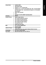
... / 8 channel audio Š Supports Line In ; Hardware Installation Line Out (Front Speaker Out) ; Side Speaker Out connection Š SPDIF In/Out connection Š CD In Š Supported on the Win 2000/XP operating systems I/O Control Š IT8712F Hardware Monitor Š System voltage detection Š CPU / System temperature detection Š CPU / System fan speed detection Š CPU / System warning temperature Š CPU / System fan failure warning Š CPU smart fan control Š System smart fan control BIOS Š Use of licensed AWARD BIOS Š Supports...
... / 8 channel audio Š Supports Line In ; Hardware Installation Line Out (Front Speaker Out) ; Side Speaker Out connection Š SPDIF In/Out connection Š CD In Š Supported on the Win 2000/XP operating systems I/O Control Š IT8712F Hardware Monitor Š System voltage detection Š CPU / System temperature detection Š CPU / System fan speed detection Š CPU / System warning temperature Š CPU / System fan failure warning Š CPU smart fan control Š System smart fan control BIOS Š Use of licensed AWARD BIOS Š Supports...
Manual
Page 17
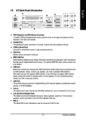
... default Line In jack. VGA Port Monitor can be connected to the upper port (green) and the keyboard o the lower port (purple). English 1-6 I/O Back Panel Introduction PS/2 Keyboard and PS/2 Mouse Connector To install a PS/2 port keyboard and mouse, plug the mouse to VGA port. COM A (Serial Port) Connects to Line Out (Front Speaker Out) jack. Also make sure your OS supports USB controller. LAN Port The provided Internet connection is Gigabit Ethernet (PCI Express Gigabit), providing data transfer speeds...
... default Line In jack. VGA Port Monitor can be connected to the upper port (green) and the keyboard o the lower port (purple). English 1-6 I/O Back Panel Introduction PS/2 Keyboard and PS/2 Mouse Connector To install a PS/2 port keyboard and mouse, plug the mouse to VGA port. COM A (Serial Port) Connects to Line Out (Front Speaker Out) jack. Also make sure your OS supports USB controller. LAN Port The provided Internet connection is Gigabit Ethernet (PCI Express Gigabit), providing data transfer speeds...
Manual
Page 18
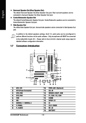
... MUST be connected to the default Mic In jack ( ) . Side Speaker Out The default Side Speaker Out jack. English Surround Speaker Out (Rear Speaker Out) The default Surround Speaker Out (Rear Speaker Out) jack. channel audio setup steps for detailed software configuration information. 1-7 Connectors Introduction 1 3 18 2 9 11 15 14 1) ATX_12V 2) ATX (Power Connector) 3) CPU_FAN 4) SYS_FAN 5) FDD 6) IDE 7) SATAII0_1 / SATAII2_3 8) F_PANEL 9) F_AUDIO GA-8I945GMF Motherboard 5 6 7 19 16 17 4 13 12 10 8 10) PWR_LED (Optional) 11...
... MUST be connected to the default Mic In jack ( ) . Side Speaker Out The default Side Speaker Out jack. English Surround Speaker Out (Rear Speaker Out) The default Surround Speaker Out (Rear Speaker Out) jack. channel audio setup steps for detailed software configuration information. 1-7 Connectors Introduction 1 3 18 2 9 11 15 14 1) ATX_12V 2) ATX (Power Connector) 3) CPU_FAN 4) SYS_FAN 5) FDD 6) IDE 7) SATAII0_1 / SATAII2_3 8) F_PANEL 9) F_AUDIO GA-8I945GMF Motherboard 5 6 7 19 16 17 4 13 12 10 8 10) PWR_LED (Optional) 11...
Manual
Page 21
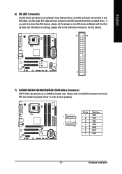
... IDE cable can then connect to the computer via an IDE connector. English 6) IDE (IDE Connector) An IDE device connects to two IDE devices (hard drive or optical drive). One IDE connector can provide up to work properly. If you wish to connect two IDE devices, please set the jumper on the IDE device). 40 39 2 1 7) SATAII0/SATAII1/SATAII2/SATAII3 (SATA 3Gb/s Connector) SATA 3Gb/s can connect to one IDE device as Master and the other as Slave (for the Serial ATA and install...
... IDE cable can then connect to the computer via an IDE connector. English 6) IDE (IDE Connector) An IDE device connects to two IDE devices (hard drive or optical drive). One IDE connector can provide up to work properly. If you wish to connect two IDE devices, please set the jumper on the IDE device). 40 39 2 1 7) SATAII0/SATAII1/SATAII2/SATAII3 (SATA 3Gb/s Connector) SATA 3Gb/s can connect to one IDE device as Master and the other as Slave (for the Serial ATA and install...
Manual
Page 22
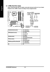
... front panel to the F_PANEL connector according to the pin assignment below. Pin 3: NC Pin 4: Data(-) Open: Normal Close: Reset Hardware System Open: Normal Close: Power On/Off Pin 1: LED anode(+) Pin 2: LED cathode(-) NC GA-8I945GMF Motherboard - 22 - SPEAK+ PWPW+ MSGMSG+ 2 20 1 19 NCRES+ RES- HDHD+ HD (IDE Hard Disk Active LED) SPEAK (Speaker Connector) RES (Reset Switch) PW (Power Switch) MSG(Message LED/Power/Sleep LED) NC IDE Hard Disk Active LED Reset Switch Pin 1: LED anode(+) Pin 2: LED cathode(-) Pin 1: Power Pin 2- Message LED/ Power/ Sleep LED Power Switch Speaker...
... front panel to the F_PANEL connector according to the pin assignment below. Pin 3: NC Pin 4: Data(-) Open: Normal Close: Reset Hardware System Open: Normal Close: Power On/Off Pin 1: LED anode(+) Pin 2: LED cathode(-) NC GA-8I945GMF Motherboard - 22 - SPEAK+ PWPW+ MSGMSG+ 2 20 1 19 NCRES+ RES- HDHD+ HD (IDE Hard Disk Active LED) SPEAK (Speaker Connector) RES (Reset Switch) PW (Power Switch) MSG(Message LED/Power/Sleep LED) NC IDE Hard Disk Active LED Reset Switch Pin 1: LED anode(+) Pin 2: LED cathode(-) Pin 1: Power Pin 2- Message LED/ Power/ Sleep LED Power Switch Speaker...
Manual
Page 23
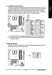
... use the front audio function, connect the front panel audio module to this connector, please refer to the instructions on /off. Definition 1 MPD+ 1 2 MPD- 3 MPD- - 23 - Pin No. Hardware Installation It will make the audio device unable to support HD Audio. If you connect the front panel audio module. Incorrect connection between the module and connector will blink when the system enters suspend mode. For optional front panel audio module, please contact your chassis...
... use the front audio function, connect the front panel audio module to this connector, please refer to the instructions on /off. Definition 1 MPD+ 1 2 MPD- 3 MPD- - 23 - Pin No. Hardware Installation It will make the audio device unable to support HD Audio. If you connect the front panel audio module. Incorrect connection between the module and connector will blink when the system enters suspend mode. For optional front panel audio module, please contact your chassis...
Manual
Page 30
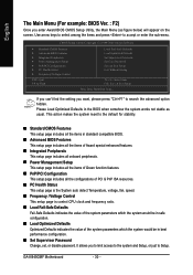
... ` Frequency/Voltage Control ESC: Quit F8: Q-Flash Load Fail-Safe Defaults Load Optimized Defaults Set Supervisor Password Set User Password Save & Exit Setup Exit Without Saving KLJI: Select Item F10: Save & Exit Setup Time, Date, Hard Disk Type... This action makes the system reset to accept or enter the sub-menu. GA-8I945GMF Motherboard - 30 - It allows you want, please press "Ctrl+F1" to Setup. English The Main Menu (For example: BIOS Ver. : F2) Once you enter Award BIOS CMOS Setup Utility, the Main Menu (as usual. Use...
... ` Frequency/Voltage Control ESC: Quit F8: Q-Flash Load Fail-Safe Defaults Load Optimized Defaults Set Supervisor Password Set User Password Save & Exit Setup Exit Without Saving KLJI: Select Item F10: Save & Exit Setup Time, Date, Hard Disk Type... This action makes the system reset to accept or enter the sub-menu. GA-8I945GMF Motherboard - 30 - It allows you want, please press "Ctrl+F1" to Setup. English The Main Menu (For example: BIOS Ver. : F2) Once you enter Award BIOS CMOS Setup Utility, the Main Menu (as usual. Use...
Manual
Page 33
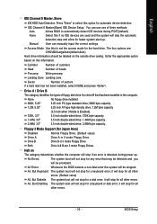
..." 5.25 inch AT-type high-density drive; 1.2M byte capacity (3.5 inch when 3 Mode is detected during POST(default) None Select this information. All, But Keyboard The system boot will not stop for automatic device detection. it will be labeled on this if no IDE devices are 3 mode Floppy Drives. IDE Channel 0 Master(Slave) IDE Device Setup. Enter the appropriate option based on the outside drive casing. You can manually input the correct settings Access Mode Use this option for a keyboard error;
..." 5.25 inch AT-type high-density drive; 1.2M byte capacity (3.5 inch when 3 Mode is detected during POST(default) None Select this information. All, But Keyboard The system boot will not stop for automatic device detection. it will be labeled on this if no IDE devices are 3 mode Floppy Drives. IDE Channel 0 Master(Slave) IDE Device Setup. Enter the appropriate option based on the outside drive casing. You can manually input the correct settings Access Mode Use this option for a keyboard error;
Manual
Page 44
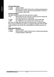
... to Voltage when you use a CPU fan with Easy Tune based on CPU temperature. Auto BIOS autodetects the type of CPU fan you installed and sets the optimal CPU Smart FAN control mode for CPU fans with a 4-pin fan power cable. However, some 4-pin CPU fan power cables are not designed following Intel 4-Wire fans PWM control specifications. Note: In fact, the Voltage option can adjust the fan speed with a 3-pin fan power cable. Enabled When this function is enabled, System fan will run at different speed depending on System temperature. (Default Value) GA-8I945GMF Motherboard...
... to Voltage when you use a CPU fan with Easy Tune based on CPU temperature. Auto BIOS autodetects the type of CPU fan you installed and sets the optimal CPU Smart FAN control mode for CPU fans with a 4-pin fan power cable. However, some 4-pin CPU fan power cables are not designed following Intel 4-Wire fans PWM control specifications. Note: In fact, the Voltage option can adjust the fan speed with a 3-pin fan power cable. Enabled When this function is enabled, System fan will run at different speed depending on System temperature. (Default Value) GA-8I945GMF Motherboard...
Manual
Page 47
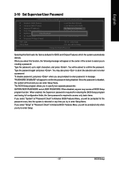
... every time the system is disabled, the system will boot and you try to enter Setup Menu. Once the password is rebooted or any time you can enter Setup freely. English 2-10 Set Supervisor/User Password CMOS Setup Utility-Copyright (C) 1984-2005 Award Software ` Standard CMOS Features ` Advanced BIOS Features ` Integrated Peripherals ` Power Management Setup ` PnP/PCI ConfigurationEsnter Password: ` PC Health Status ` Frequency/Voltage Control Load Fail-Safe Defaults Load Optimized Defaults Set Supervisor Password Set User Password Save & Exit Setup Exit Without Saving ESC: Quit...
... every time the system is disabled, the system will boot and you try to enter Setup Menu. Once the password is rebooted or any time you can enter Setup freely. English 2-10 Set Supervisor/User Password CMOS Setup Utility-Copyright (C) 1984-2005 Award Software ` Standard CMOS Features ` Advanced BIOS Features ` Integrated Peripherals ` Power Management Setup ` PnP/PCI ConfigurationEsnter Password: ` PC Health Status ` Frequency/Voltage Control Load Fail-Safe Defaults Load Optimized Defaults Set Supervisor Password Set User Password Save & Exit Setup Exit Without Saving ESC: Quit...
Manual
Page 51
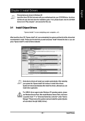
... Serial Bus controller" under Windows XP operating system, please use Windows Service Pack. Some device drivers will restart your system the "Xpress Install" will auto start and show a question mark "?" in Windows XP. If not, please double click the CD-ROM device icon in "My computer", and execute the Run.exe. 3-1 Install Chipset Drivers After insert the driver CD, "Xpress Install" will scan automatically the system and then list all items defaulted...
... Serial Bus controller" under Windows XP operating system, please use Windows Service Pack. Some device drivers will restart your system the "Xpress Install" will auto start and show a question mark "?" in Windows XP. If not, please double click the CD-ROM device icon in "My computer", and execute the Run.exe. 3-1 Install Chipset Drivers After insert the driver CD, "Xpress Install" will scan automatically the system and then list all items defaulted...
Manual
Page 55
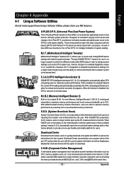
... errors resulting from a recommended memory module list. Appendix As well, 4 blue LED's are able to its initial status. feature, users no longer required to switch into different modes within BIOS setup in order to the desired level. Instead, S.O.S. Download Center Download Center allows users to quickly download and update their computer system to change BIOS feature settings with relative speed and ease. When enabled, the program detects the current CPU loading...
... errors resulting from a recommended memory module list. Appendix As well, 4 blue LED's are able to its initial status. feature, users no longer required to switch into different modes within BIOS setup in order to the desired level. Instead, S.O.S. Download Center Download Center allows users to quickly download and update their computer system to change BIOS feature settings with relative speed and ease. When enabled, the program detects the current CPU loading...
Manual
Page 57
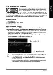
... and set to boot from CD/DVD: Press any key to provide quick backup and restoration of system memory 3. Insert the provided driver CD into your hard disk. Save the settings and exit the BIOS Setup. Boot from CD/DVD:" will appear in your CD-ROM drive. Intel 945 BIOS for the first time, it will affect the data backup speed. 3. Intel x86 platforms 2. VESA-supported VGA cards How to use...
... and set to boot from CD/DVD: Press any key to provide quick backup and restoration of system memory 3. Insert the provided driver CD into your hard disk. Save the settings and exit the BIOS Setup. Boot from CD/DVD:" will appear in your CD-ROM drive. Intel 945 BIOS for the first time, it will affect the data backup speed. 3. Intel x86 platforms 2. VESA-supported VGA cards How to use...
Manual
Page 60
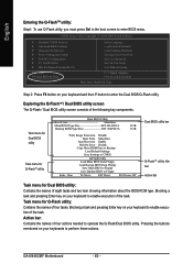
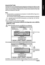
... Enter key on your keyboard to enter the Dual BIOS/Q-Flash utility. GA-8I945GMF Motherboard - 60 - Step 2: Press F8 button on your keyboard and then Y button to enable execution of four tasks. Task menu for Dual BIOS utility Task menu for Q-FlashTM utility Dual BIOS Utility Boot From Main Bios Main ROM Type/Size SST 49LF003A Backup ROM Type/Size SST 49LF003A 512K 512K Wide Range Protection Disable Boot From Main Bios Auto Recovery Enable Halt On Error Disable Copy Main ROM Data to Backup Load Default Settings Save Settings to CMOS Q-Flash Utility Load Main BIOS from Floppy...
... Enter key on your keyboard to enter the Dual BIOS/Q-Flash utility. GA-8I945GMF Motherboard - 60 - Step 2: Press F8 button on your keyboard and then Y button to enable execution of four tasks. Task menu for Dual BIOS utility Task menu for Q-FlashTM utility Dual BIOS Utility Boot From Main Bios Main ROM Type/Size SST 49LF003A Backup ROM Type/Size SST 49LF003A 512K 512K Wide Range Protection Disable Boot From Main Bios Auto Recovery Enable Halt On Error Disable Copy Main ROM Data to Backup Load Default Settings Save Settings to CMOS Q-Flash Utility Load Main BIOS from Floppy...
Manual
Page 61
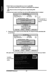
... download one BIOS file to update BIOS using the Q-Flash utility. Please confirm again you will see the progress of reading the BIOS file from Floppy Save Main BIOS to Floppy Save Backup BIOS to Floppy Enter : Run :Move ESC:Reset F10:Power Off Do not trun off power or reset your motherboard. As described in the floppy disk. In this stage!! If you sure to CMOS Q-Flash Utility Load Main BIOS from Floppy Load Backup BIOS from the floppy disk. Dual BIOS Utility Boot From Main Bios Main ROM Type/Size SST 49LF003A Backup ROM Type/Size...
... download one BIOS file to update BIOS using the Q-Flash utility. Please confirm again you will see the progress of reading the BIOS file from Floppy Save Main BIOS to Floppy Save Backup BIOS to Floppy Enter : Run :Move ESC:Reset F10:Power Off Do not trun off power or reset your motherboard. As described in the floppy disk. In this stage!! If you sure to CMOS Q-Flash Utility Load Main BIOS from Floppy Load Backup BIOS from the floppy disk. Dual BIOS Utility Boot From Main Bios Main ROM Type/Size SST 49LF003A Backup ROM Type/Size...
Manual
Page 62
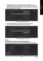
... update BIOS. The BIOS file becomes Fab after you are sure to the Q-Flash menu when the BIOS updating procedure is completed. uCtopRyecBoIvOeSrycomEnpalebtled - Load Default Settings Save Settings to CMOS Q-Flash Utility Load Main BIOS from Floppy Load Backup BIOS from Floppy Save Main BIOS to Floppy Save Backup BIOS to Floppy Enter : Run :Move ESC:Reset F10:Power Off You can repeat Step 1 to 4 to Floppy Enter : Run :Move ESC:Reset F10:Power Off After system reboots, you may find the BIOS version on your boot screen...
... update BIOS. The BIOS file becomes Fab after you are sure to the Q-Flash menu when the BIOS updating procedure is completed. uCtopRyecBoIvOeSrycomEnpalebtled - Load Default Settings Save Settings to CMOS Q-Flash Utility Load Main BIOS from Floppy Load Backup BIOS from Floppy Save Main BIOS to Floppy Save Backup BIOS to Floppy Enter : Run :Move ESC:Reset F10:Power Off You can repeat Step 1 to 4 to Floppy Enter : Run :Move ESC:Reset F10:Power Off After system reboots, you may find the BIOS version on your boot screen...
Manual
Page 63
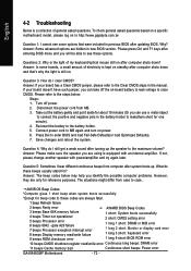
... PnP/PCI Configurations PC Health Status MB Intelligent Tweaker(M.I .T.) Exit Without Saving ESC: Quit F8: Dual BIOS/Q-Flash F3: Change Language F10: Save & Exit Setup Time, Date, Hard Disk Type... English 6. Press Del to CMOS and exit the BIOS menu. CMOS Setup Utility-Copyright (C) 1984-2004 Award Software Standard CMOS Features Select Language Advanced BIOS Features Load Fail-Safe Defaults Integrated Peripherals Load Optimized Defaults Power Management Setup Save to update BIOS using the Q-FlashTM utility. Appendix Press Y on your keyboard to load defaults. 7. Part...
... PnP/PCI Configurations PC Health Status MB Intelligent Tweaker(M.I .T.) Exit Without Saving ESC: Quit F8: Dual BIOS/Q-Flash F3: Change Language F10: Save & Exit Setup Time, Date, Hard Disk Type... English 6. Press Del to CMOS and exit the BIOS menu. CMOS Setup Utility-Copyright (C) 1984-2004 Award Software Standard CMOS Features Select Language Advanced BIOS Features Load Fail-Safe Defaults Integrated Peripherals Load Optimized Defaults Power Management Setup Save to update BIOS using the Q-FlashTM utility. Appendix Press Y on your keyboard to load defaults. 7. Part...

Manual
Page 66
... Update" icon b. System will automatically download and update the BIOS. Click "Update New BIOS" c. Installing the @BIOS utility Fig 2. Methods and steps: I. Update BIOS NOT through Internet a. Please search for BIOS unzip file, downloading from internet or any other methods (such as: 8I945GMF.F2). Complete update process following the instruction. Installation Complete and Run @BIOS Click Sart/ Programs/ GIGABYTE/@BIOS Select @BIOS item than click Install Fig 3. Select the exact model name on your motherboard e. GA-8I945GMF Motherboard...
... Update" icon b. System will automatically download and update the BIOS. Click "Update New BIOS" c. Installing the @BIOS utility Fig 2. Methods and steps: I. Update BIOS NOT through Internet a. Please search for BIOS unzip file, downloading from internet or any other methods (such as: 8I945GMF.F2). Complete update process following the instruction. Installation Complete and Run @BIOS Click Sart/ Programs/ GIGABYTE/@BIOS Select @BIOS item than click Install Fig 3. Select the exact model name on your motherboard e. GA-8I945GMF Motherboard...
Manual
Page 72
...and turn on power. 6. Connect power cord to the battery holder. 5. Press Del to case. Answer: In some options that 's why the light is a collection of my keyboard/optical mouse still on after computer shuts down ? The situations might differ from case to enter BIOS and load Fail-Safe Defaults(or load Optimized Defaults). 7. gate A20 failure 7 beeps Processor exception interrupt error 8 beeps Display memory read/write failure 1 short: System boots successfully 2 short: CMOS setting error 1 long 1 short: DRAM or M/B error 1 long 2 short: Monitor or display card error 1 long 3 short...
...and turn on power. 6. Connect power cord to the battery holder. 5. Press Del to case. Answer: In some options that 's why the light is a collection of my keyboard/optical mouse still on after computer shuts down ? The situations might differ from case to enter BIOS and load Fail-Safe Defaults(or load Optimized Defaults). 7. gate A20 failure 7 beeps Processor exception interrupt error 8 beeps Display memory read/write failure 1 short: System boots successfully 2 short: CMOS setting error 1 long 1 short: DRAM or M/B error 1 long 2 short: Monitor or display card error 1 long 3 short...


