Manual
Page 4
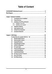
Table of Content GA-8I945GMF Motherboard Layout 6 Block Diagram ...7 Chapter 1 Hardware Installation 9 1-1 Considerations Prior to Installation 9 1-2 Feature Summary 10 1-3 Installation of the CPU and Heatsink 12 1-3-1 Installation of the CPU 12 1-3-2 Installation of the Heatsink 13 1-4 Installation of Memory 14 1-5 Install expansion cards 16 1-6 I/O Back Panel Introduction 17 1-7 Connectors Introduction 18 Chapter 2 BIOS Setup 29...
Table of Content GA-8I945GMF Motherboard Layout 6 Block Diagram ...7 Chapter 1 Hardware Installation 9 1-1 Considerations Prior to Installation 9 1-2 Feature Summary 10 1-3 Installation of the CPU and Heatsink 12 1-3-1 Installation of the CPU 12 1-3-2 Installation of the Heatsink 13 1-4 Installation of Memory 14 1-5 Install expansion cards 16 1-6 I/O Back Panel Introduction 17 1-7 Connectors Introduction 18 Chapter 2 BIOS Setup 29...

Manual
Page 9
Prior to wear an electrostatic discharge (ESD) cuff when handling electronic components (CPU, RAM). 4. Please verify that all cables and power connectors are no leftover screws or metal components placed on the motherboard or within a electrostatic shielding ... determined to installation, please do not remove the stickers on top of the motherboard or any metal leads or connectors. 3. Prior to be an unofficial Gigabyte product. - 9 - Before using the product, please verify that you are required for warranty validation. 2. To prevent damage to the motherboard, please do not...
Prior to wear an electrostatic discharge (ESD) cuff when handling electronic components (CPU, RAM). 4. Please verify that all cables and power connectors are no leftover screws or metal components placed on the motherboard or within a electrostatic shielding ... determined to installation, please do not remove the stickers on top of the motherboard or any metal leads or connectors. 3. Prior to be an unofficial Gigabyte product. - 9 - Before using the product, please verify that you are required for warranty validation. 2. To prevent damage to the motherboard, please do not...
Manual
Page 10
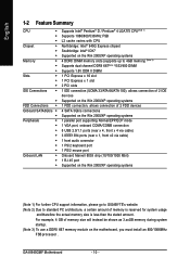
For example, 4 GB of memory is reserved for system usage and therefore the actual memory size is less than the stated amount. GA-8I945GMF Motherboard - 10 - English 1-2 Feature Summary CPU Š Š Š Chipset Š Š Š Memory Š Š Š Slots Š Š Š IDE Connections &#... (10/100/1000 Mbit) 1 RJ 45 port Supported on the Win 2000/XP operating systems (Note 1) For further CPU support information, please go to GIGABYTE's website. (Note 2) Due to standard PC architecture, a certain amount of memory size will instead be shown as 3....
For example, 4 GB of memory is reserved for system usage and therefore the actual memory size is less than the stated amount. GA-8I945GMF Motherboard - 10 - English 1-2 Feature Summary CPU Š Š Š Chipset Š Š Š Memory Š Š Š Slots Š Š Š IDE Connections &#... (10/100/1000 Mbit) 1 RJ 45 port Supported on the Win 2000/XP operating systems (Note 1) For further CPU support information, please go to GIGABYTE's website. (Note 2) Due to standard PC architecture, a certain amount of memory size will instead be shown as 3....
Manual
Page 11
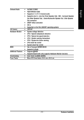
... the Win 2000/XP operating systems I/O Control Š IT8712F Hardware Monitor Š System voltage detection Š CPU / System temperature detection Š CPU / System fan speed detection Š CPU / System warning temperature Š CPU / System fan failure warning Š CPU smart fan control Š System smart fan control BIOS Š Use of licensed AWARD BIOS Š...
... the Win 2000/XP operating systems I/O Control Š IT8712F Hardware Monitor Š System voltage detection Š CPU / System temperature detection Š CPU / System fan speed detection Š CPU / System warning temperature Š CPU / System fan failure warning Š CPU smart fan control Š System smart fan control BIOS Š Use of licensed AWARD BIOS Š...
Manual
Page 12
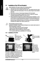
...® Pentium 4 Processor with HT Technology - Fig. 4 Once the CPU is installed on the CPU socket to the CPU during installation.) GA-8I945GMF Motherboard - 12 - If this occurs, please change the insert direction of the CPU. It is not recommended that supports HT Technology and has it into the socket in a straight and downwards motion. Chipset...
...® Pentium 4 Processor with HT Technology - Fig. 4 Once the CPU is installed on the CPU socket to the CPU during installation.) GA-8I945GMF Motherboard - 12 - If this occurs, please change the insert direction of the CPU. It is not recommended that supports HT Technology and has it into the socket in a straight and downwards motion. Chipset...

Manual
Page 13
...Hardware Installation Fig. 6 Finally, please attach the power connector of the installed CPU. Fig. 2 (Turning the push pin along the direction of arrow is ... and Female push pin are joined closely. (for Intel boxed fan) Fig. 3 Place the heatsink atop the CPU and make sure the push pins aim to the pin hole on the motherboard.Pressing down the push pins diagonally....layer of heatsink paste on the surface of the heatsink to the CPU fan header located on the motherboard. The heatsink may adhere to the CPU as the picture, the installation is suggested that either thermal tape rather...
...Hardware Installation Fig. 6 Finally, please attach the power connector of the installed CPU. Fig. 2 (Turning the push pin along the direction of arrow is ... and Female push pin are joined closely. (for Intel boxed fan) Fig. 3 Place the heatsink atop the CPU and make sure the push pins aim to the pin hole on the motherboard.Pressing down the push pins diagonally....layer of heatsink paste on the surface of the heatsink to the CPU fan header located on the motherboard. The heatsink may adhere to the CPU as the picture, the installation is suggested that either thermal tape rather...
Manual
Page 19
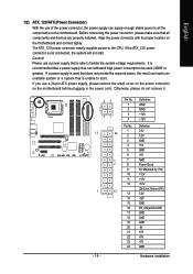
...) 3.3V -12V GND PS_ON(soft On/Off) GND GND GND -5V +5V +5V +5V GND - 19 - If the ATX_12V power connector is able to the CPU. Please use a 24-pin ATX power supply, please remove the small cover on the power connector on the motherboard and connect tightly. Hardware Installation Before...
...) 3.3V -12V GND PS_ON(soft On/Off) GND GND GND -5V +5V +5V +5V GND - 19 - If the ATX_12V power connector is able to the CPU. Please use a 24-pin ATX power supply, please remove the small cover on the power connector on the motherboard and connect tightly. Hardware Installation Before...
Manual
Page 20
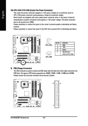
... connection and requires a +12V power voltage. Please remember to connect the power to the CPU fan to the FDD drive. Please remember to connect the power to the cooler to the pin1 position. 34 33 GA-8I945GMF Motherboard 2 1 - 20 - Caution! Most coolers are : 360KB, 720KB, 1.2MB..., 1.44MB and 2.88MB. The types of the cable connects to prevent CPU overheating and failure. 1 CPU_FAN 1 SYS_FAN Pin No. 1 2 3 4 Definition...
... connection and requires a +12V power voltage. Please remember to connect the power to the CPU fan to the FDD drive. Please remember to connect the power to the cooler to the pin1 position. 34 33 GA-8I945GMF Motherboard 2 1 - 20 - Caution! Most coolers are : 360KB, 720KB, 1.2MB..., 1.44MB and 2.88MB. The types of the cable connects to prevent CPU overheating and failure. 1 CPU_FAN 1 SYS_FAN Pin No. 1 2 3 4 Definition...
Manual
Page 30
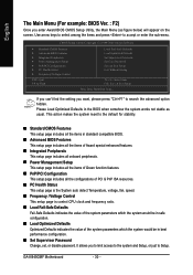
...PC Health Status This setup page is the System auto detect Temperature, voltage, fan, speed. „ Frequency / Voltage Control This setup page is control CPU clock and frequency ratio. „ Load Fail-Safe Defaults Fail-Safe Defaults indicates the value of the system parameters which the system would be in...system parameters which the system would be in the BIOS when somehow the system works not stable as figure below) will appear on the screen. GA-8I945GMF Motherboard - 30 - If you can't find the setting you to limit access to the system and Setup, or just to search the advanced...
...PC Health Status This setup page is the System auto detect Temperature, voltage, fan, speed. „ Frequency / Voltage Control This setup page is control CPU clock and frequency ratio. „ Load Fail-Safe Defaults Fail-Safe Defaults indicates the value of the system parameters which the system would be in...system parameters which the system would be in the BIOS when somehow the system works not stable as figure below) will appear on the screen. GA-8I945GMF Motherboard - 30 - If you can't find the setting you to limit access to the system and Setup, or just to search the advanced...
Manual
Page 34
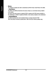
... is typically 512K for systems with 512K memory installed on the motherboard, or 640K for systems with 640K or more memory installed on the motherboard. GA-8I945GMF Motherboard - 34 - This is determined by POST (Power On Self Test) of the BIOS. Base Memory The POST of the BIOS will determine the amount... of base (or conventional) memory installed in the CPU's memory address map. English Memory The category is display-only which is the amount of memory located above 1 MB in the system.
... is typically 512K for systems with 512K memory installed on the motherboard, or 640K for systems with 640K or more memory installed on the motherboard. GA-8I945GMF Motherboard - 34 - This is determined by POST (Power On Self Test) of the BIOS. Base Memory The POST of the BIOS will determine the amount... of base (or conventional) memory installed in the CPU's memory address map. English Memory The category is display-only which is the amount of memory located above 1 MB in the system.
Manual
Page 35
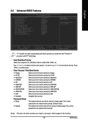
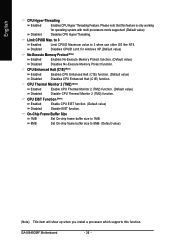
...1984-2005 Award Software Advanced BIOS Features ` Hard Disk Boot Priority First Boot Device Second Boot Device Third Boot Device Password Check # CPU Hyper-Threading Limit CPUID Max. First / Second / Third Boot Device Floppy Select your boot device priority by Floppy. Hard Disk Select...entered at the prompt. (Default value) The system will not boot and will not access to 3 No-Execute Memory Protect (Note) CPU Enhanced Halt (C1E) (Note) CPU Thermal Monitor 2(TM2) (Note) CPU EIST Function (Note) On-Chip Frame Buffer Size [Press Enter] [Floppy] [Hard Disk] [CDROM] [Setup] [Enabled] [...
...1984-2005 Award Software Advanced BIOS Features ` Hard Disk Boot Priority First Boot Device Second Boot Device Third Boot Device Password Check # CPU Hyper-Threading Limit CPUID Max. First / Second / Third Boot Device Floppy Select your boot device priority by Floppy. Hard Disk Select...entered at the prompt. (Default value) The system will not boot and will not access to 3 No-Execute Memory Protect (Note) CPU Enhanced Halt (C1E) (Note) CPU Thermal Monitor 2(TM2) (Note) CPU EIST Function (Note) On-Chip Frame Buffer Size [Press Enter] [Floppy] [Hard Disk] [CDROM] [Setup] [Enabled] [...
Manual
Page 36
.... 8MB Set On-chip frame buffer size to 3 when use older OS like NT4. Limit CPUID Max. CPU EIST Function (Note) Enabled Enable CPU EIST function. (Default value) Disabled Disable EIST function. to 3 Enabled Disabled Limit CPUID Maximum value to 8MB... Memory Protect function. (Default value) Disabled Disables No-Execute Memory Protect function. CPU Enhanced Halt (C1E) (Note) Enabled Disabled Enables CPU Enhanced Halt (C1E) function. (Default value) Disables CPU Enhanced Halt (C1E) function. GA-8I945GMF Motherboard - 36 - Please note that this function. English...
.... 8MB Set On-chip frame buffer size to 3 when use older OS like NT4. Limit CPUID Max. CPU EIST Function (Note) Enabled Enable CPU EIST function. (Default value) Disabled Disable EIST function. to 3 Enabled Disabled Limit CPUID Maximum value to 8MB... Memory Protect function. (Default value) Disabled Disables No-Execute Memory Protect function. CPU Enhanced Halt (C1E) (Note) Enabled Disabled Enables CPU Enhanced Halt (C1E) function. (Default value) Disables CPU Enhanced Halt (C1E) function. GA-8I945GMF Motherboard - 36 - Please note that this function. English...
Manual
Page 43
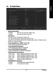
... DDRV +3.3V +12V Current System Temperature Current CPU Temperature Current CPU FAN Speed Current SYSTEM FAN Speed System Warning Temperature CPU Warning Temperature CPU FAN Fail Warning SYSTEM FAN Fail Warning CPU Smart FAN Control CPU Smart FAN Mode System Smart FAN Control [Disabled...) Clear case open status at 90oC / 194oF. Current System/CPU Temperature Detect System/CPU temperature automatically. CPU/System Warning Temperature 60oC / 140oF Monitor CPU/System temperature at 60oC / 140oF. 70oC / 158oF 80oC / 176oF Monitor CPU/System temperature at 70oC / 158oF. If you want to reset...
... DDRV +3.3V +12V Current System Temperature Current CPU Temperature Current CPU FAN Speed Current SYSTEM FAN Speed System Warning Temperature CPU Warning Temperature CPU FAN Fail Warning SYSTEM FAN Fail Warning CPU Smart FAN Control CPU Smart FAN Mode System Smart FAN Control [Disabled...) Clear case open status at 90oC / 194oF. Current System/CPU Temperature Detect System/CPU temperature automatically. CPU/System Warning Temperature 60oC / 140oF Monitor CPU/System temperature at 60oC / 140oF. 70oC / 158oF 80oC / 176oF Monitor CPU/System temperature at 70oC / 158oF. If you want to reset...

Manual
Page 44
Enabled When this function is enabled, System fan will run at different speed depending on System temperature. (Default Value) GA-8I945GMF Motherboard - 44 - Enabled When this function is enabled. PWM Set to Voltage when you use a CPU fan with 3-pin or 4-pin power cables. System Smart FAN Control Disabled Disable this function. However, some...
Enabled When this function is enabled, System fan will run at different speed depending on System temperature. (Default Value) GA-8I945GMF Motherboard - 44 - Enabled When this function is enabled. PWM Set to Voltage when you use a CPU fan with 3-pin or 4-pin power cables. System Smart FAN Control Disabled Disable this function. However, some...
Manual
Page 45
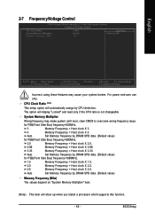
... (Note) This setup option will display "Locked" and read only if the CPU ratio is not changeable. Auto Set Memory frequency by DRAM SPD data. (Default value) Memory Frequency (Mhz) The values depend on "System ..., 3 Memory Frequency = Host clock X 3. 4 Memory Frequency = Host clock X 4. Auto Set Memory frequency by CPU detection. English 2-7 Frequency/Voltage Control CMOS Setup Utility-Copyright (C) 1984-2005 Award Software Frequency/Voltage Control CPU Clock Ratio System Memory Multiplier Memory Frequency (Mhz) [16X] [Auto] 533 Item Help Menu Level` KLJI: Move...
... (Note) This setup option will display "Locked" and read only if the CPU ratio is not changeable. Auto Set Memory frequency by DRAM SPD data. (Default value) Memory Frequency (Mhz) The values depend on "System ..., 3 Memory Frequency = Host clock X 3. 4 Memory Frequency = Host clock X 4. Auto Set Memory frequency by CPU detection. English 2-7 Frequency/Voltage Control CMOS Setup Utility-Copyright (C) 1984-2005 Award Software Frequency/Voltage Control CPU Clock Ratio System Memory Multiplier Memory Frequency (Mhz) [16X] [Auto] 533 Item Help Menu Level` KLJI: Move...
Manual
Page 55
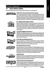
... Overclock Saver (S.O.S.) is a unique feature that allows system hardware information such as the CPU system bus, memory timings or to the desired level. With GIGABYTE's proprietary S.O.S. Download Center automatically runs a system check of the user PC and provides...to 10%. allows corporate MIS engineers to maximize system performance. M.I .B. 2 features. C.I.A.2 (CPU Intelligent Accelerator 2) GIGABYTE CPU Intelligent Accelerator 2(C.I .B. 2) is designed to automatically adjust CPU computing power to easily maintain corporate computers such as displaying a detailed list of all new ...
... Overclock Saver (S.O.S.) is a unique feature that allows system hardware information such as the CPU system bus, memory timings or to the desired level. With GIGABYTE's proprietary S.O.S. Download Center automatically runs a system check of the user PC and provides...to 10%. allows corporate MIS engineers to maximize system performance. M.I .B. 2 features. C.I.A.2 (CPU Intelligent Accelerator 2) GIGABYTE CPU Intelligent Accelerator 2(C.I .B. 2) is designed to automatically adjust CPU computing power to easily maintain corporate computers such as displaying a detailed list of all new ...
Manual
Page 56
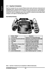
... 1. GIGABYTE Logo Log on different motherboards. for special enhancement for CPU and Memory, 3) Smart-Fan control for managing fan speed control of CPU frequency 8. English 4-1-1 EasyTune 5 Introduction EasyTune 5 presents the most convenient Windows based system performance enhancement and manageability utility. C.I.A./C.I.A.2 and M.I.B./M.I.B.2 Enters the C.I.A./2 and M.I .B. Smart-Fan Enters the Smart-Fan setting page 4. GA-8I945GMF Motherboard...
... 1. GIGABYTE Logo Log on different motherboards. for special enhancement for CPU and Memory, 3) Smart-Fan control for managing fan speed control of CPU frequency 8. English 4-1-1 EasyTune 5 Introduction EasyTune 5 presents the most convenient Windows based system performance enhancement and manageability utility. C.I.A./C.I.A.2 and M.I.B./M.I.B.2 Enters the C.I.A./2 and M.I .B. Smart-Fan Enters the Smart-Fan setting page 4. GA-8I945GMF Motherboard...


