Manual
Page 4
...GA-8I915P-MF Motherboard Layout 6 Block Diagram ...7 Chapter 1 Hardware Installation 9 1-1 Considerations Prior to Installation 9 1-2 Feature Summary 10 1-3 Installation of the CPU and Heatsink 12 1-3-1 Installation of the CPU 12 1-3-2 Installation of the Heatsink 13 1-4 Installation of Memory 14 1-5 Install expansion cards 16 1-6 I/O Back Panel Introduction 17 1-7 Connectors Introduction 18 Chapter 2 BIOS... Setup 29 The Main Menu (For example: BIOS Ver. : F4 30 2-1 Standard CMOS Features 32 2-2 Advanced BIOS Features 34 2-3 IntegratedPeripherals ...
...GA-8I915P-MF Motherboard Layout 6 Block Diagram ...7 Chapter 1 Hardware Installation 9 1-1 Considerations Prior to Installation 9 1-2 Feature Summary 10 1-3 Installation of the CPU and Heatsink 12 1-3-1 Installation of the CPU 12 1-3-2 Installation of the Heatsink 13 1-4 Installation of Memory 14 1-5 Install expansion cards 16 1-6 I/O Back Panel Introduction 17 1-7 Connectors Introduction 18 Chapter 2 BIOS... Setup 29 The Main Menu (For example: BIOS Ver. : F4 30 2-1 Standard CMOS Features 32 2-2 Advanced BIOS Features 34 2-3 IntegratedPeripherals ...

Manual
Page 5
Channel Audio Function Introduction 65 4-2 Troubleshooting 69 - 5 - Chapter 3 Install Drivers 47 3-1 Install Chipset Drivers 47 3-2 SoftwareApplications 48 3-3 Driver CD Information 48 3-4 Hardware Information 49 3-5 Contact Us ...49 Chapter 4 Appendix 51 4-1 Unique Software Utilities 51 4-1-1 EasyTune 5 Introduction 52 4-1-2 Xpress Recovery Introduction 53 4-1-3 Flash BIOS Method Introduction 56 4-1-4 2- / 4- / 6- / 8-
Channel Audio Function Introduction 65 4-2 Troubleshooting 69 - 5 - Chapter 3 Install Drivers 47 3-1 Install Chipset Drivers 47 3-2 SoftwareApplications 48 3-3 Driver CD Information 48 3-4 Hardware Information 49 3-5 Contact Us ...49 Chapter 4 Appendix 51 4-1 Unique Software Utilities 51 4-1-1 EasyTune 5 Introduction 52 4-1-2 Xpress Recovery Introduction 53 4-1-3 Flash BIOS Method Introduction 56 4-1-4 2- / 4- / 6- / 8-

Manual
Page 6
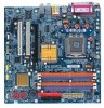
GA-8I915P-MF Motherboard Layout IT8712 KB_MS SPDIF_O SPDIF_I CPU_FAN SYS_FAN IR ATX COMA LPT R_USB ATX_12V LGA775 GA-8I915P-MF DDR1 DDR2 USB LAN AZALIA_FP AUDIO1 AUDIO2 PCIE_16 RTL8110S CD_IN CODEC PCIE_1 COMB Intel 915P IDE FDD DDR3 DDR4 PCI1 PCI2 ICH6 TSB43AB23 F2_1394 F1_1394 F_USB1 F_USB2 BAT S_ATA3 S_ATA2 S_ATA1 S_ATA0 BIOS CLR_CMOS PWR_LED F_PANEL - 6 -
GA-8I915P-MF Motherboard Layout IT8712 KB_MS SPDIF_O SPDIF_I CPU_FAN SYS_FAN IR ATX COMA LPT R_USB ATX_12V LGA775 GA-8I915P-MF DDR1 DDR2 USB LAN AZALIA_FP AUDIO1 AUDIO2 PCIE_16 RTL8110S CD_IN CODEC PCIE_1 COMB Intel 915P IDE FDD DDR3 DDR4 PCI1 PCI2 ICH6 TSB43AB23 F2_1394 F1_1394 F_USB1 F_USB2 BAT S_ATA3 S_ATA2 S_ATA1 S_ATA0 BIOS CLR_CMOS PWR_LED F_PANEL - 6 -

Manual
Page 7
... 2 PCI LGA775 Processor CPUCLK+/-(200/133MHz) Host Interface DDR400/333MHz DIMM Intel 915P GMCH Dual Channel Memory GMCHCLK (133/200MHz) 66MHz 33MHz 14.318MHz 48MHz BIOS 4 Serial ATA Intel ATA33/66/100 ICH6 IDE Channels Floppy IT 8712 LPT Port COM Ports CODEC 8 USB Ports 24MHz 33MHz PS/2 KB/Mouse PCICLK...
... 2 PCI LGA775 Processor CPUCLK+/-(200/133MHz) Host Interface DDR400/333MHz DIMM Intel 915P GMCH Dual Channel Memory GMCHCLK (133/200MHz) 66MHz 33MHz 14.318MHz 48MHz BIOS 4 Serial ATA Intel ATA33/66/100 ICH6 IDE Channels Floppy IT 8712 LPT Port COM Ports CODEC 8 USB Ports 24MHz 33MHz PS/2 KB/Mouse PCICLK...

Manual
Page 11
Hardware Installation English Hardware Monitor Š System voltage detection Š CPU temperature detection Š CPU / System fan speed detection Š CPU warning temperature Š CPU / System fan failure warning Š CPU smart fan control BIOS Š Use of licensed AWARD BIOS Š Supports Q-Flash Additional Features Š Supports @BIOS Š Supports EasyTune5 (only supports Hardware Monitor function) Overclocking Š Over Clock via BIOS (DDR) Form Factor Š Micro ATX form factor; 24.4 cm x 24.4cm - 11 -
Hardware Installation English Hardware Monitor Š System voltage detection Š CPU temperature detection Š CPU / System fan speed detection Š CPU warning temperature Š CPU / System fan failure warning Š CPU smart fan control BIOS Š Use of licensed AWARD BIOS Š Supports Q-Flash Additional Features Š Supports @BIOS Š Supports EasyTune5 (only supports Hardware Monitor function) Overclocking Š Over Clock via BIOS (DDR) Form Factor Š Micro ATX form factor; 24.4 cm x 24.4cm - 11 -

Manual
Page 12
...located on the edge of the CPU Metal Lever Fig. 1 Gently lift the metal lever located on the CPU socket to the CPU during installation.) GA-8I915P-MF Motherboard - 12 - HT functionality requirement content : Enabling the functionality of Hyper-Threading Technology for the peripherals. Avoid twisting or bending motions that the system... graphics card, memory, hard drive, etc. Fig. 2 Remove the plastic covering on the CPU prior to your thumb and forefinger, carefully place it enabled - BIOS: A BIOS that has optimizations for HT Technology 1-3-1 Installation of the CPU socket.
...located on the edge of the CPU Metal Lever Fig. 1 Gently lift the metal lever located on the CPU socket to the CPU during installation.) GA-8I915P-MF Motherboard - 12 - HT functionality requirement content : Enabling the functionality of Hyper-Threading Technology for the peripherals. Avoid twisting or bending motions that the system... graphics card, memory, hard drive, etc. Fig. 2 Remove the plastic covering on the CPU prior to your thumb and forefinger, carefully place it enabled - BIOS: A BIOS that has optimizations for HT Technology 1-3-1 Installation of the CPU socket.
Manual
Page 14
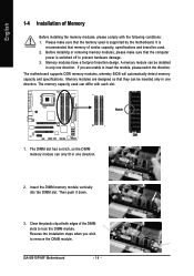
.... It is supported by the motherboard. The motherboard supports DDR memory modules, whereby BIOS will automatically detect memory capacity and specifications. The memory capacity used . 2. Insert the DIMM memory module vertically into the DIMM slot. Then push it down. 3. GA-8I915P-MF Motherboard - 14 - Close the plastic clip at both edges of the DIMM...
.... It is supported by the motherboard. The motherboard supports DDR memory modules, whereby BIOS will automatically detect memory capacity and specifications. The memory capacity used . 2. Insert the DIMM memory module vertically into the DIMM slot. Then push it down. 3. GA-8I915P-MF Motherboard - 14 - Close the plastic clip at both edges of the DIMM...

Manual
Page 16
... the small whitedrawable bar at the end of the PCI Express x 16 slot when you try to secure the slot bracket of expansion card from BIOS. 8. GA-8I915P-MF Motherboard - 16 - Be sure the metal contacts on the card are indeed seated in motherboard. 4. Replace your VGA card is locked by following the steps... computer's chassis cover. 7. Please align the VGA card to the onboard PCI Express x 16 slot and press firmly down on the computer, if necessary, setup BIOS utility of the expansion card. 6. Press the expansion card firmly into the computer. 2.
... the small whitedrawable bar at the end of the PCI Express x 16 slot when you try to secure the slot bracket of expansion card from BIOS. 8. GA-8I915P-MF Motherboard - 16 - Be sure the metal contacts on the card are indeed seated in motherboard. 4. Replace your VGA card is locked by following the steps... computer's chassis cover. 7. Please align the VGA card to the onboard PCI Express x 16 slot and press firmly down on the computer, if necessary, setup BIOS utility of the expansion card. 6. Press the expansion card firmly into the computer. 2.

Manual
Page 21
Pin No. Hardware Installation Please refer to the BIOS setting for information on settings, please refer to the instructions located on one IDE cable, and the single IDE cable can connect to one IDE ...
Pin No. Hardware Installation Please refer to the BIOS setting for information on settings, please refer to the instructions located on one IDE cable, and the single IDE cable can connect to one IDE ...

Manual
Page 23
Definition 1 MPD+ 1 2 MPD- 3 MPD- 10) AZALIA_FP (Front Audio Connector) This connector is supported to AC97. - 23 - To enable AC'97 Audio, from BIOS settings, set Front Panel Type under Integrated Peripherals to connect HD(High Definition) Audio and AC'97 Audio. For optional audio panel cable, please contact ...
Definition 1 MPD+ 1 2 MPD- 3 MPD- 10) AZALIA_FP (Front Audio Connector) This connector is supported to AC97. - 23 - To enable AC'97 Audio, from BIOS settings, set Front Panel Type under Integrated Peripherals to connect HD(High Definition) Audio and AC'97 Audio. For optional audio panel cable, please contact ...

Manual
Page 29
... to the CMOS SETUP screen. You can be reset to its original settings. If you wish to upgrade to a new BIOS, either Gigabyte's Q-Flash or @BIOS utility can enter the BIOS setup screen by pressing "Ctrl + F1". Exit current page and return to select item Select Item Main Menu - The ...CMOS SETUP saves the configuration in the event that BIOS needs to activate certain system features. When the power is displayed at ...
... to the CMOS SETUP screen. You can be reset to its original settings. If you wish to upgrade to a new BIOS, either Gigabyte's Q-Flash or @BIOS utility can enter the BIOS setup screen by pressing "Ctrl + F1". Exit current page and return to select item Select Item Main Menu - The ...CMOS SETUP saves the configuration in the event that BIOS needs to activate certain system features. When the power is displayed at ...
Manual
Page 30
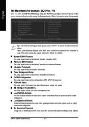
... best performance configuration. „ Set Supervisor Password Change, set, or disable password. GA-8I915P-MF Motherboard - 30 - CMOS Setup Utility-Copyright (C) 1984-2004 Award Software ` Standard CMOS Features ` Advanced BIOS Features ` Integrated Peripherals ` Power Management Setup ` PnP/PCI Configurations ` PC Health...default for stability. „ Standard CMOS Features This setup page includes all the items in standard compatible BIOS. „ Advanced BIOS Features This setup page includes all the items of Award special enhanced features. „ Integrated Peripherals This ...
... best performance configuration. „ Set Supervisor Password Change, set, or disable password. GA-8I915P-MF Motherboard - 30 - CMOS Setup Utility-Copyright (C) 1984-2004 Award Software ` Standard CMOS Features ` Advanced BIOS Features ` Integrated Peripherals ` Power Management Setup ` PnP/PCI Configurations ` PC Health...default for stability. „ Standard CMOS Features This setup page includes all the items in standard compatible BIOS. „ Advanced BIOS Features This setup page includes all the items of Award special enhanced features. „ Integrated Peripherals This ...

Manual
Page 31
BIOS Setup English „ Set User Password Change, set, or disable password. It allows you to limit access to the system. „ Save & Exit Setup Save CMOS value settings to CMOS and exit setup. „ Exit Without Saving Abandon all CMOS value changes and exit setup. - 31 -
BIOS Setup English „ Set User Password Change, set, or disable password. It allows you to limit access to the system. „ Save & Exit Setup Save CMOS value settings to CMOS and exit setup. „ Exit Without Saving Abandon all CMOS value changes and exit setup. - 31 -

Manual
Page 32
... this if no IDE devices are : CHS/LBA/Large/Auto(default:Auto) Hard drive information should be labeled on this option for the hard drive. GA-8I915P-MF Motherboard - 32 - Week The week, from 1 to 2098 KLJI: Move Enter: Select F5: Previous Values +/-/PU/PD: Value F10: Save F6:... casing. Cylinder Number of cylinders Head Number of heads Precomp Write precomp Landing Zone Landing zone Sector Number of three methods: Auto Allows BIOS to Sat, determined by the BIOS and is , , , . IDE Channel 0 Master, Slave IDE HDD Auto-Detection Press "Enter" to Dec. The time is 13...
... this if no IDE devices are : CHS/LBA/Large/Auto(default:Auto) Hard drive information should be labeled on this option for the hard drive. GA-8I915P-MF Motherboard - 32 - Week The week, from 1 to 2098 KLJI: Move Enter: Select F5: Previous Values +/-/PU/PD: Value F10: Save F6:... casing. Cylinder Number of cylinders Head Number of heads Precomp Write precomp Landing Zone Landing zone Sector Number of three methods: Auto Allows BIOS to Sat, determined by the BIOS and is , , , . IDE Channel 0 Master, Slave IDE HDD Auto-Detection Press "Enter" to Dec. The time is 13...

Manual
Page 33
..., 5.25" 5.25 inch AT-type high-density drive; 1.2M byte capacity (3.5 inch when 3 Mode is 3 mode Floppy Drive. Whenever the BIOS detects a non-fatal error the system will stop for Japan Area) Disabled Normal Floppy Drive. (Default value) Drive A Drive B Both Drive A... is the amount of the BIOS. Drive B is Enabled). 720K, 3.5" 1.44M, 3.5" 3.5 inch double-sided drive; 720K byte capacity 3.5 inch double-sided drive; 1.44M byte capacity. 2.88M...
..., 5.25" 5.25 inch AT-type high-density drive; 1.2M byte capacity (3.5 inch when 3 Mode is 3 mode Floppy Drive. Whenever the BIOS detects a non-fatal error the system will stop for Japan Area) Disabled Normal Floppy Drive. (Default value) Drive A Drive B Both Drive A... is the amount of the BIOS. Drive B is Enabled). 720K, 3.5" 1.44M, 3.5" 3.5 inch double-sided drive; 720K byte capacity 3.5 inch double-sided drive; 1.44M byte capacity. 2.88M...

Manual
Page 34
... CMOS Setup Utility-Copyright (C) 1984-2004 Award Software Advanced BIOS Features ` Hard Disk Boot Priority First Boot Device Second Boot Device Third Boot Device Password Check # CPU Hyper-Threading Limit CPUID Max. to Setup page ... supports this menu. USB-ZIP Select your boot device priority by LS120. First / Second / Third Boot Device Floppy Select your boot device priority by ZIP. GA-8I915P-MF Motherboard - 34 - Press to move it down the list. LS120 Select your boot device priority by USB-HDD. USB-FDD Select your boot device priority...
... CMOS Setup Utility-Copyright (C) 1984-2004 Award Software Advanced BIOS Features ` Hard Disk Boot Priority First Boot Device Second Boot Device Third Boot Device Password Check # CPU Hyper-Threading Limit CPUID Max. to Setup page ... supports this menu. USB-ZIP Select your boot device priority by LS120. First / Second / Third Boot Device Floppy Select your boot device priority by ZIP. GA-8I915P-MF Motherboard - 34 - Press to move it down the list. LS120 Select your boot device priority by USB-HDD. USB-FDD Select your boot device priority...

Manual
Page 35
... 3 when use older OS like NT4. (Default value) Disables CPUID Limit for operating system with multi processors mode supported. (Default value) Disables CPU Hyper Threading. BIOS Setup Disable CPU Thermal Monitor 2 (TM2) function. (Default value) (Note) This item will show up when you install a processor which supports this feature is only...
... 3 when use older OS like NT4. (Default value) Disables CPUID Limit for operating system with multi processors mode supported. (Default value) Disables CPU Hyper Threading. BIOS Setup Disable CPU Thermal Monitor 2 (TM2) function. (Default value) (Note) This item will show up when you install a processor which supports this feature is only...

Manual
Page 37
...Controller. (Default value) Disabled Disable USB Controller. Disabled Disable USB Keyboard Support. (Default value) USB Mouse Support Enabled Enable USB Mouse Support. BIOS Setup Enabled Enable USB 2.0 Controller. (Default value) Disabled Disable USB 2.0 Controller. HD Audio Set front audio panel type to Ch. 0 .... (Default value) Disable Azalia audio function. If PATA IDE were set to Ch. 0 Master/Slave, this function. Auto Combined BIOS will auto make by the setting "On-Chip SATA Mode" and "PATA IDE Set to". English On-Chip SATA Mode Disabled Disable...
...Controller. (Default value) Disabled Disable USB Controller. Disabled Disable USB Keyboard Support. (Default value) USB Mouse Support Enabled Enable USB Mouse Support. BIOS Setup Enabled Enable USB 2.0 Controller. (Default value) Disabled Disable USB 2.0 Controller. HD Audio Set front audio panel type to Ch. 0 .... (Default value) Disable Azalia audio function. If PATA IDE were set to Ch. 0 Master/Slave, this function. Auto Combined BIOS will auto make by the setting "On-Chip SATA Mode" and "PATA IDE Set to". English On-Chip SATA Mode Disabled Disable...

Manual
Page 38
...address is 2E8. This function will automatically setup the port 1 address. Disabled Disable onboard Serial port 1. Disable onboard Serial port 2. GA-8I915P-MF Motherboard - 38 - Onboard H/W LAN1 Enabled Enable Onboard H/W LAN1 function. (Default value) Disabled Disable this function. Enabled Enable ...this function. Disabled Disable this function. Onboard Serial Port 2 Auto 3F8/IRQ4 BIOS will automatically setup the port 2 address. IrDA Set onboard I /O chip UART to determine which Infra Red(IR) function ...
...address is 2E8. This function will automatically setup the port 1 address. Disabled Disable onboard Serial port 1. Disable onboard Serial port 2. GA-8I915P-MF Motherboard - 38 - Onboard H/W LAN1 Enabled Enable Onboard H/W LAN1 function. (Default value) Disabled Disable this function. Enabled Enable ...this function. Disabled Disable this function. Onboard Serial Port 2 Auto 3F8/IRQ4 BIOS will automatically setup the port 2 address. IrDA Set onboard I /O chip UART to determine which Infra Red(IR) function ...
Manual
Page 39
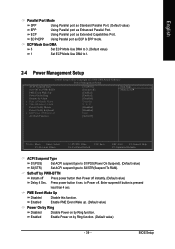
... button 4 sec. to S3/STR(Suspend To RAM). PME Event Wake Up Disabled Disable this function. Enter suspend if button is pressed less than 4 sec. BIOS Setup Enabled Enable PME Event Wake up. (Default value) Power On by Ring Disabled Disable Power on by PWR-BTTN Instant-off Press power button...
... button 4 sec. to S3/STR(Suspend To RAM). PME Event Wake Up Disabled Disable this function. Enter suspend if button is pressed less than 4 sec. BIOS Setup Enabled Enable PME Event Wake up. (Default value) Power On by Ring Disabled Disable Power on by PWR-BTTN Instant-off Press power button...


