Manual
Page 4
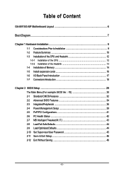
... 1-3-1 Installation of the CPU 12 1-3-2 Installation of the Heatsink 13 1-4 Installation of Memory 14 1-5 Install expansion cards 16 1-6 I/O Back Panel Introduction 17 1-7 Connectors Introduction 18 Chapter 2 BIOS Setup 29 The Main Menu (For example: BIOS Ver. : F2 30 2-1 Standard CMOS Features 32 2-2 Advanced BIOS Features 34 2-3 IntegratedPeripherals 36 2-4 Power Management Setup 39 2-5 PnP/PCI Configurations 41 2-6 PC Health Status 42 2-7 MB Intelligent Tweaker(M.I.T 43 2-8 Load Fail-Safe Defaults 44 2-9 Load Optimized Defaults 44 2-10 Set Supervisor/User Password 45...
... 1-3-1 Installation of the CPU 12 1-3-2 Installation of the Heatsink 13 1-4 Installation of Memory 14 1-5 Install expansion cards 16 1-6 I/O Back Panel Introduction 17 1-7 Connectors Introduction 18 Chapter 2 BIOS Setup 29 The Main Menu (For example: BIOS Ver. : F2 30 2-1 Standard CMOS Features 32 2-2 Advanced BIOS Features 34 2-3 IntegratedPeripherals 36 2-4 Power Management Setup 39 2-5 PnP/PCI Configurations 41 2-6 PC Health Status 42 2-7 MB Intelligent Tweaker(M.I.T 43 2-8 Load Fail-Safe Defaults 44 2-9 Load Optimized Defaults 44 2-10 Set Supervisor/User Password 45...
Manual
Page 10
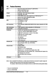
...; 1 RJ 45 port Š ALC880 CODEC Š High Definition Audio Š Supports 2 / 4 / 6 / 8 channel audio Š Supports Line In ; Surround Speaker Out (Rear Speaker Out) ; Line Out (Front Speaker Out) ; MIC ; Only for GA-8I915G-MF. GA-8I915G-MF/GA-8I915GM Motherboard - 10 - Only for GA-8I915GM. For example, 4 GB of memory size will instead be shown as 3.xxGB memory during system startup. English 1-2 Feature Summary CPU Chipset Memory Slots IDE Connections FDD Connections Onboard SATA Peripherals Onboard LAN Onboard Audio I/O Control Š Supports the latest...
...; 1 RJ 45 port Š ALC880 CODEC Š High Definition Audio Š Supports 2 / 4 / 6 / 8 channel audio Š Supports Line In ; Surround Speaker Out (Rear Speaker Out) ; Line Out (Front Speaker Out) ; MIC ; Only for GA-8I915G-MF. GA-8I915G-MF/GA-8I915GM Motherboard - 10 - Only for GA-8I915GM. For example, 4 GB of memory size will instead be shown as 3.xxGB memory during system startup. English 1-2 Feature Summary CPU Chipset Memory Slots IDE Connections FDD Connections Onboard SATA Peripherals Onboard LAN Onboard Audio I/O Control Š Supports the latest...
Manual
Page 20
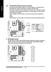
.... 34 33 2 1 GA-8I915G-MF/GA-8I915GM Motherboard - 20 - English 3/4) CPU_FAN / SYS_FAN (Cooler Fan Power Connector) The cooler fan power connector supplies a +12V power voltage via a 3-pin/4-pin (only for CPU_FAN) 5) FDD (Floppy Connector) The FDD connector is the ground wire (GND). The black connector wire is used to connect the FDD cable while the other end of FDD drives supported are designed with color-coded power connector wires. The types of the cable connects to the FDD drive. Please connect the red power connector wire to prevent...
.... 34 33 2 1 GA-8I915G-MF/GA-8I915GM Motherboard - 20 - English 3/4) CPU_FAN / SYS_FAN (Cooler Fan Power Connector) The cooler fan power connector supplies a +12V power voltage via a 3-pin/4-pin (only for CPU_FAN) 5) FDD (Floppy Connector) The FDD connector is the ground wire (GND). The black connector wire is used to connect the FDD cable while the other end of FDD drives supported are designed with color-coded power connector wires. The types of the cable connects to the FDD drive. Please connect the red power connector wire to prevent...
Manual
Page 21
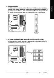
... 7 GND - 21 - Please refer to the BIOS setting for information on settings, please refer to the instructions located on the IDE device). 40 39 2 1 7) S_ATA0/S_ATA1/S_ATA2/S_ATA3 (Serial ATA Connector, Controlled by ICH6) Serial ATA can then connect to connect two IDE devices, please set the jumper on one IDE cable, and the single IDE cable can provide 150MB/s transfer rate. If you wish to two IDE devices (hard drive or optical drive). Hardware Installation Pin No.
... 7 GND - 21 - Please refer to the BIOS setting for information on settings, please refer to the instructions located on the IDE device). 40 39 2 1 7) S_ATA0/S_ATA1/S_ATA2/S_ATA3 (Serial ATA Connector, Controlled by ICH6) Serial ATA can then connect to connect two IDE devices, please set the jumper on one IDE cable, and the single IDE cable can provide 150MB/s transfer rate. If you wish to two IDE devices (hard drive or optical drive). Hardware Installation Pin No.
Manual
Page 22
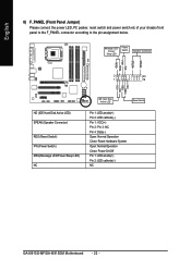
... IDE Hard Disk Active LED Reset Switch Pin 1: LED anode(+) Pin 2: LED cathode(-) Pin 1: VCC(+) Pin 2- SPEAK+ PWPW+ MSGMSG+ 2 20 1 19 NCRES+ RES- English 8) F_PANEL (Front Panel Jumper) Please connect the power LED, PC peaker, reset switch and power switch etc of your chassis front panel to the F_PANEL connector according to the pin assignment below. Pin 3: NC Pin 4: Data(-) Open: Normal Operation Close: Reset Hardware System Open: Normal Operation Close: Power On/Off Pin 1: LED anode(+) Pin 2: LED cathode(-) NC GA-8I915G-MF/GA-8I915GM Motherboard...
... IDE Hard Disk Active LED Reset Switch Pin 1: LED anode(+) Pin 2: LED cathode(-) Pin 1: VCC(+) Pin 2- SPEAK+ PWPW+ MSGMSG+ 2 20 1 19 NCRES+ RES- English 8) F_PANEL (Front Panel Jumper) Please connect the power LED, PC peaker, reset switch and power switch etc of your chassis front panel to the F_PANEL connector according to the pin assignment below. Pin 3: NC Pin 4: Data(-) Open: Normal Operation Close: Reset Hardware System Open: Normal Operation Close: Power On/Off Pin 1: LED anode(+) Pin 2: LED cathode(-) NC GA-8I915G-MF/GA-8I915GM Motherboard...
Manual
Page 30
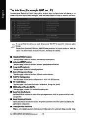
Use arrow keys to select among the items and press to Setup. Please Load Optimized Defaults in best performance configuration. „ Set Supervisor Password Change, set, or disable password. It allows you to limit access to the system and Setup, or just to accept or enter the sub-menu. GA-8I915G-MF/GA-8I915GM Motherboard - 30 - This action makes the system reset to search the advanced option hidden. CMOS Setup Utility-Copyright (C) 1984-2004 Award Software ` Standard CMOS Features...
Use arrow keys to select among the items and press to Setup. Please Load Optimized Defaults in best performance configuration. „ Set Supervisor Password Change, set, or disable password. It allows you to limit access to the system and Setup, or just to accept or enter the sub-menu. GA-8I915G-MF/GA-8I915GM Motherboard - 30 - This action makes the system reset to search the advanced option hidden. CMOS Setup Utility-Copyright (C) 1984-2004 Award Software ` Standard CMOS Features...
Manual
Page 32
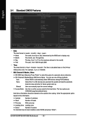
...) CMOS Setup Utility-Copyright (C) 1984-2004 Award Software Standard CMOS Features Thu, Apr 29 2004 22:31:24 Item Help Menu Level` ` IDE Channel 0 Master ` IDE Channel 0 Slave [None] [None] Change the day, month, year Drive A Drive B Floppy 3 Mode Suport Holt On [1.44M, 3.5"] [None] [Disabled] [All, But Keyboard] Sun. Enter the appropriate option based on the 24-hour military-time clock. The time is 13:00:00. IDE Channel 0 Master, Slave IDE HDD Auto-Detection Press "Enter...
...) CMOS Setup Utility-Copyright (C) 1984-2004 Award Software Standard CMOS Features Thu, Apr 29 2004 22:31:24 Item Help Menu Level` ` IDE Channel 0 Master ` IDE Channel 0 Slave [None] [None] Change the day, month, year Drive A Drive B Floppy 3 Mode Suport Holt On [1.44M, 3.5"] [None] [Disabled] [All, But Keyboard] Sun. Enter the appropriate option based on the 24-hour military-time clock. The time is 13:00:00. IDE Channel 0 Master, Slave IDE HDD Auto-Detection Press "Enter...
Manual
Page 34
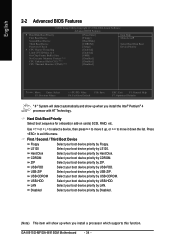
... your boot device priority by Floppy. USB-HDD Select your boot device priority by CDROM. English 2-2 Advanced BIOS Features CMOS Setup Utility-Copyright (C) 1984-2004 Award Software Advanced BIOS Features ` Hard Disk Boot Priority First Boot Device Second Boot Device Third Boot Device Password Check # CPU Hyper-Threading Limit CPUID Max. Hard Disk Boot Priority Select boot sequence for onboard(or add-on cards) SCSI, RAID, etc. First / Second / Third Boot Device Floppy Select your boot device priority by LAN. LS120 Select your boot device priority by USB-HDD. LAN Select...
... your boot device priority by Floppy. USB-HDD Select your boot device priority by CDROM. English 2-2 Advanced BIOS Features CMOS Setup Utility-Copyright (C) 1984-2004 Award Software Advanced BIOS Features ` Hard Disk Boot Priority First Boot Device Second Boot Device Third Boot Device Password Check # CPU Hyper-Threading Limit CPUID Max. Hard Disk Boot Priority Select boot sequence for onboard(or add-on cards) SCSI, RAID, etc. First / Second / Third Boot Device Floppy Select your boot device priority by LAN. LS120 Select your boot device priority by USB-HDD. LAN Select...
Manual
Page 37
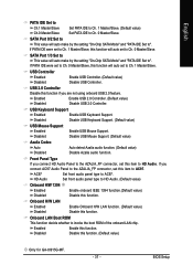
...HD Audio Set front audio panel type to invoke the boot ROM of the onboard LAN chip. SATA Port 1/3 Set to This value will auto make by the setting "On-Chip SATA Mode" and "PATA IDE Set to ". Onboard H/W LAN Enabled Enable Onboard H/W LAN function. (Default value) Disabled Disable this function if you are not using onboard USB 2.0 feature. Disabled Disable this function. Enabled Enable USB 2.0 Controller. (Default value) Disabled Disable USB 2.0 Controller. SATA Port 0/2 Set to This value will auto make by the setting "On-Chip SATA Mode" and "PATA IDE Set...
...HD Audio Set front audio panel type to invoke the boot ROM of the onboard LAN chip. SATA Port 1/3 Set to This value will auto make by the setting "On-Chip SATA Mode" and "PATA IDE Set to ". Onboard H/W LAN Enabled Enable Onboard H/W LAN function. (Default value) Disabled Disable this function if you are not using onboard USB 2.0 feature. Disabled Disable this function. Enabled Enable USB 2.0 Controller. (Default value) Disabled Disable USB 2.0 Controller. SATA Port 0/2 Set to This value will auto make by the setting "On-Chip SATA Mode" and "PATA IDE Set...
Manual
Page 43
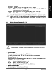
..., clear CMOS to Voltage when you use only. For power end-user use a CPU fan with 3-pin or 4-pin power cables. BIOS Setup However, some 4-pin CPU fan power cables are not designed following Intel 4-wire fans PWM control specifications. Auto BIOS autodetects the type of CPU fan you installed and sets the optimal CPU Smart FAN control mode for FSB(Front Side Bus) frequency=800MHz, 2.0 Memory Frequency = Host clock X 2.0. 2.66 Memory Frequency = Host clock X 2.66. With such CPU fans, selecting PWM will display "Locked" and read only if the CPU ratio is enabled...
..., clear CMOS to Voltage when you use only. For power end-user use a CPU fan with 3-pin or 4-pin power cables. BIOS Setup However, some 4-pin CPU fan power cables are not designed following Intel 4-wire fans PWM control specifications. Auto BIOS autodetects the type of CPU fan you installed and sets the optimal CPU Smart FAN control mode for FSB(Front Side Bus) frequency=800MHz, 2.0 Memory Frequency = Host clock X 2.0. 2.66 Memory Frequency = Host clock X 2.66. With such CPU fans, selecting PWM will display "Locked" and read only if the CPU ratio is enabled...
Manual
Page 45
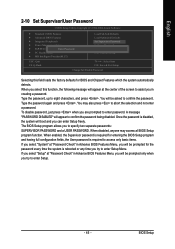
... User password is disabled, the system will be prompted only when you try to enter Setup. - 45 - You may access all BIOS Setup program function. BIOS Setup You will appear to eight characters, and press . English 2-10 Set Supervisor/User Password CMOS Setup Utility-Copyright (C) 1984-2004 Award Software ` Standard CMOS Features ` Advanced BIOS Features ` Integrated Peripherals ` Power Management Setup ` PnP/PCI ConfigurationEsnter Password: ` PC Health Status ` MB Intelligent Tweaker(M.I.T.) Load Fail-Safe Defaults Load Optimized Defaults Set Supervisor Password Set User...
... User password is disabled, the system will be prompted only when you try to enter Setup. - 45 - You may access all BIOS Setup program function. BIOS Setup You will appear to eight characters, and press . English 2-10 Set Supervisor/User Password CMOS Setup Utility-Copyright (C) 1984-2004 Award Software ` Standard CMOS Features ` Advanced BIOS Features ` Integrated Peripherals ` Power Management Setup ` PnP/PCI ConfigurationEsnter Password: ` PC Health Status ` MB Intelligent Tweaker(M.I.T.) Load Fail-Safe Defaults Load Optimized Defaults Set Supervisor Password Set User...

Manual
Page 47
.... 3-1 Install Chipset Drivers After insert the driver CD, "Xpress Install" will auto start and show a question mark "?" Please pick the item that recommended to install other drivers. English Chapter 3 Install Drivers Pictures below are shown in "Universal Serial Bus controller" under Windows XP operating system, please use Windows Service Pack. For USB2.0 driver support under "Device Manager". Install Drivers or you want and press "install" followed the item; System will show the installation guide. After install Windows Service Pack...
.... 3-1 Install Chipset Drivers After insert the driver CD, "Xpress Install" will auto start and show a question mark "?" Please pick the item that recommended to install other drivers. English Chapter 3 Install Drivers Pictures below are shown in "Universal Serial Bus controller" under Windows XP operating system, please use Windows Service Pack. For USB2.0 driver support under "Device Manager". Install Drivers or you want and press "install" followed the item; System will show the installation guide. After install Windows Service Pack...
Manual
Page 51
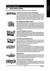
...-date drivers and BIOS. - 51 - for download. Appendix C.I.A.2 (CPU Intelligent Accelerator 2) GIGABYTE CPU Intelligent Accelerator 2(C.I .B. 2 features. automatically resets the overclocked system settings back to their BIOS as well as the CPU system bus, memory timings or to enabled Gigabyte's unique C.I.A. 2 and M.I .A. 2) is no longer need to open up the PC chassis and short-circuit the "Clear CMOS" pins or the battery on the motherboard to reset the system back to provide a more user-friendly...
...-date drivers and BIOS. - 51 - for download. Appendix C.I.A.2 (CPU Intelligent Accelerator 2) GIGABYTE CPU Intelligent Accelerator 2(C.I .B. 2 features. automatically resets the overclocked system settings back to their BIOS as well as the CPU system bus, memory timings or to enabled Gigabyte's unique C.I.A. 2 and M.I .A. 2) is no longer need to open up the PC chassis and short-circuit the "Clear CMOS" pins or the battery on the motherboard to reset the system back to provide a more user-friendly...

Manual
Page 53
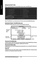
... you complete installations of the screen. Appendix System requirements: 1. Save the settings and exit the BIOS Setup. Press any key to enter Xpress Recovery2 without the CD-ROM. Intel 945 BIOS for the first time, it will appear in your CD-ROM drive. Insert the provided driver CD into your hard disk. Upon system restart, the message which says "Boot from CD/DVD: Press any key to...
... you complete installations of the screen. Appendix System requirements: 1. Save the settings and exit the BIOS Setup. Press any key to enter Xpress Recovery2 without the CD-ROM. Intel 945 BIOS for the first time, it will appear in your CD-ROM drive. Insert the provided driver CD into your hard disk. Upon system restart, the message which says "Boot from CD/DVD: Press any key to...
Manual
Page 56
... names of four tasks. Task menu for Dual BIOS utility: Contains the names of the following key components. CMOS Setup Utility-Copyright (C) 1984-2004 Award Software Standard CMOS Features Advanced BIOS Features Integrated Peripherals Power Management Setup PnP/PCI Configurations PC Health Status MB Intelligent Tweaker(M.I.T.) ESC: Quit F8: Dual BIOS/Q-Flash Select Language Load Fail-Safe Defaults Load Optimized Defaults Set Supervisor Password Set User Password Save & Exit Setup Exit Without Saving F3: Change Language F10: Save & Exit Setup Time, Date, Hard Disk Type...
... names of four tasks. Task menu for Dual BIOS utility: Contains the names of the following key components. CMOS Setup Utility-Copyright (C) 1984-2004 Award Software Standard CMOS Features Advanced BIOS Features Integrated Peripherals Power Management Setup PnP/PCI Configurations PC Health Status MB Intelligent Tweaker(M.I.T.) ESC: Quit F8: Dual BIOS/Q-Flash Select Language Load Fail-Safe Defaults Load Optimized Defaults Set Supervisor Password Set User Password Save & Exit Setup Exit Without Saving F3: Change Language F10: Save & Exit Setup Time, Date, Hard Disk Type...
Manual
Page 57
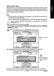
... Save Settings to CMOS Q-Flash Utility Load Main BIOS from Floppy Load Backup BIOS from Floppy Save Main BIOS to Floppy Save Backup BIOS to update BIOS using the Q-Flash utility. If you sure to Floppy" item. 2. Move to the BIOS file you want to save the current BIOS for backup purpose, you can begin " section above, you begin Step 1 with "Save Main BIOS to update BIOS?" - 57 - As described in the Q-Flash menu and press Enter button. Dual BIOS Utility Boot From Main Bios Main ROM Type/Size SST 49LF003A Backup ROM Type/Size...
... Save Settings to CMOS Q-Flash Utility Load Main BIOS from Floppy Load Backup BIOS from Floppy Save Main BIOS to Floppy Save Backup BIOS to update BIOS using the Q-Flash utility. If you sure to Floppy" item. 2. Move to the BIOS file you want to save the current BIOS for backup purpose, you can begin " section above, you begin Step 1 with "Save Main BIOS to update BIOS?" - 57 - As described in the Q-Flash menu and press Enter button. Dual BIOS Utility Boot From Main Bios Main ROM Type/Size SST 49LF003A Backup ROM Type/Size...
Manual
Page 58
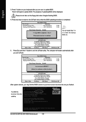
... Error Disable CPopleyasMe apirneRssOaMnyDkaetya tto cBoanctkiunpue Load Default Settings Save Settings to CMOS Q-Flash Utility Load Main BIOS from Floppy Load Backup BIOS from Floppy Save Main BIOS to Floppy Save Backup BIOS to Floppy Enter : Run :Move ESC:Reset F10:Power Off After system reboots, you may find the BIOS version on your boot screen becomes the one you are sure to the Q-Flash menu when the BIOS updating procedure is completed. Press Y button on your keyboard after updating. Press any keys to return to update BIOS...
... Error Disable CPopleyasMe apirneRssOaMnyDkaetya tto cBoanctkiunpue Load Default Settings Save Settings to CMOS Q-Flash Utility Load Main BIOS from Floppy Load Backup BIOS from Floppy Save Main BIOS to Floppy Save Backup BIOS to Floppy Enter : Run :Move ESC:Reset F10:Power Off After system reboots, you may find the BIOS version on your boot screen becomes the one you are sure to the Q-Flash menu when the BIOS updating procedure is completed. Press Y button on your keyboard after updating. Press any keys to return to update BIOS...
Manual
Page 59
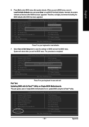
.../PCI Configurations PC Health Status MB Intelligent Tweaker(M.I .T.) Exit Without Saving ESC: Quit F8: Dual BIOS/Q-Flash F3: Change Language F10: Save & Exit Setup Time, Date, Hard Disk Type... Therefore, we highly recommend reloading the BIOS defaults after you are in BIOS menu, move to Load Fail-Safe Defaults item and press Enter to load defaults. 7. Press Y on your keyboard to load BIOS Fail-Safe Defaults. Select Save & Exit Setup item to update BIOS using the Q-FlashTM utility. CMOS Setup Utility-Copyright (C) 1984-2004 Award Software...
.../PCI Configurations PC Health Status MB Intelligent Tweaker(M.I .T.) Exit Without Saving ESC: Quit F8: Dual BIOS/Q-Flash F3: Change Language F10: Save & Exit Setup Time, Date, Hard Disk Type... Therefore, we highly recommend reloading the BIOS defaults after you are in BIOS menu, move to Load Fail-Safe Defaults item and press Enter to load defaults. 7. Press Y on your keyboard to load BIOS Fail-Safe Defaults. Select Save & Exit Setup item to update BIOS using the Q-FlashTM utility. CMOS Setup Utility-Copyright (C) 1984-2004 Award Software...
Manual
Page 62
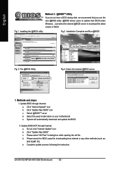
... d. d. Complete update process following the instruction. English Method 2 : @BIOSTM Utility If you do not have a DOS startup disk, we recommend that you use the new @BIOS utility. @BIOS allows users to download the latest version of BIOS. Click "Internet Update" icon b. Click "Update New BIOS" c. Update BIOS through Internet: a. Select the exact model name on your motherboard e. GA-8I915G-MF/GA-8I915GM Motherboard - 62 - Click "Update New BIOS" icon c. Do not click "Internet Update" icon b. e. Installation Complete...
... d. d. Complete update process following the instruction. English Method 2 : @BIOSTM Utility If you do not have a DOS startup disk, we recommend that you use the new @BIOS utility. @BIOS allows users to download the latest version of BIOS. Click "Internet Update" icon b. Click "Update New BIOS" c. Update BIOS through Internet: a. Select the exact model name on your motherboard e. GA-8I915G-MF/GA-8I915GM Motherboard - 62 - Click "Update New BIOS" icon c. Do not click "Internet Update" icon b. e. Installation Complete...
Manual
Page 68
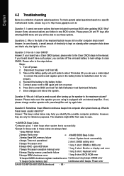
... Processor exception interrupt error 8 beeps Display memory read/write failure 1 short: System boots successfully 2 short: CMOS setting error 1 long 1 short: DRAM or M/B error 1 long 2 short: Monitor or display card error 1 long 3 short: Keyboard error 9 beeps ROM checksum error 1 long 9 short: BIOS ROM error 10 beeps CMOS shutdown register read/write error Continuous long beeps: DRAM error 11 beeps Cache memory bad Continuous short beeps: Power error GA-8I915G-MF/GA-8I915GM Motherboard - 68 - Why? Disconnect the power cord from case to enter BIOS and load Fail-Safe Defaults...
... Processor exception interrupt error 8 beeps Display memory read/write failure 1 short: System boots successfully 2 short: CMOS setting error 1 long 1 short: DRAM or M/B error 1 long 2 short: Monitor or display card error 1 long 3 short: Keyboard error 9 beeps ROM checksum error 1 long 9 short: BIOS ROM error 10 beeps CMOS shutdown register read/write error Continuous long beeps: DRAM error 11 beeps Cache memory bad Continuous short beeps: Power error GA-8I915G-MF/GA-8I915GM Motherboard - 68 - Why? Disconnect the power cord from case to enter BIOS and load Fail-Safe Defaults...


