Manual
Page 4
Table of Content GA-8I915G-MF Motherboard Layout 6 Block Diagram ...7 Chapter 1 Hardware Installation 9 1-1 Considerations Prior to Installation 9 1-2 Feature Summary 10 1-3 Installation of the CPU and Heatsink 12 1-3-1 Installation of the CPU 12 1-3-2 Installation of the Heatsink 13 1-4 Installation of Memory 14 1-5 Install expansion cards 16 1-6 I/O Back Panel Introduction 17 1-7 Connectors Introduction 18 Chapter 2 BIOS Setup 29...
Table of Content GA-8I915G-MF Motherboard Layout 6 Block Diagram ...7 Chapter 1 Hardware Installation 9 1-1 Considerations Prior to Installation 9 1-2 Feature Summary 10 1-3 Installation of the CPU and Heatsink 12 1-3-1 Installation of the CPU 12 1-3-2 Installation of the Heatsink 13 1-4 Installation of Memory 14 1-5 Install expansion cards 16 1-6 I/O Back Panel Introduction 17 1-7 Connectors Introduction 18 Chapter 2 BIOS Setup 29...
Manual
Page 10
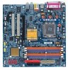
... memory is reserved for system usage and therefore the actual memory size is less than the stated amount. GA-8I915G-MF/GA-8I915GM Motherboard - 10 - Line Out (Front Speaker Out) ; Only for GA-8I915GM. MIC ; English 1-2 Feature Summary CPU Chipset Memory Slots IDE Connections FDD Connections Onboard SATA Peripherals Onboard LAN Onboard Audio I/O Control Š Supports...
... memory is reserved for system usage and therefore the actual memory size is less than the stated amount. GA-8I915G-MF/GA-8I915GM Motherboard - 10 - Line Out (Front Speaker Out) ; Only for GA-8I915GM. MIC ; English 1-2 Feature Summary CPU Chipset Memory Slots IDE Connections FDD Connections Onboard SATA Peripherals Onboard LAN Onboard Audio I/O Control Š Supports...
Manual
Page 12
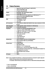
... to your computer system requires all of the following conditions: 1. Fig. 3 Notice the small gold colored triangle located on the CPU socket to the CPU during installation.) GA-8I915G-MF/GA-8I915GM Motherboard - 12 - OS: An operation system that might cause damage to the upright position. Avoid twisting or bending motions that has optimizations for your...
... to your computer system requires all of the following conditions: 1. Fig. 3 Notice the small gold colored triangle located on the CPU socket to the CPU during installation.) GA-8I915G-MF/GA-8I915GM Motherboard - 12 - OS: An operation system that might cause damage to the upright position. Avoid twisting or bending motions that has optimizations for your...
Manual
Page 20
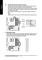
...other end of FDD drives supported are designed with color-coded power connector wires. Caution! Please remember to connect the power to the CPU fan to prevent CPU overheating and failure. 1 CPU_FAN 1 SYS_FAN Pin No. 1 2 3 4 Definition GND +12V Sense Speed Control (Only for CPU_FAN... FDD connector is the ground wire (GND). Please remember to connect the power to the cooler to the pin1 position. 34 33 2 1 GA-8I915G-MF/GA-8I915GM Motherboard - 20 - A red power connector wire indicates a positive connection and requires a +12V power voltage. Most coolers are : 360KB, 720KB, ...
...other end of FDD drives supported are designed with color-coded power connector wires. Caution! Please remember to connect the power to the CPU fan to prevent CPU overheating and failure. 1 CPU_FAN 1 SYS_FAN Pin No. 1 2 3 4 Definition GND +12V Sense Speed Control (Only for CPU_FAN... FDD connector is the ground wire (GND). Please remember to connect the power to the cooler to the pin1 position. 34 33 2 1 GA-8I915G-MF/GA-8I915GM Motherboard - 20 - A red power connector wire indicates a positive connection and requires a +12V power voltage. Most coolers are : 360KB, 720KB, ...
Manual
Page 30
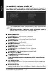
...Set User Password Save & Exit Setup Exit Without Saving KLJI: Select Item F10: Save & Exit Setup Time, Date, Hard Disk Type... GA-8I915G-MF/GA-8I915GM Motherboard - 30 - CMOS Setup Utility-Copyright (C) 1984-2004 Award Software ` Standard CMOS Features ` Advanced BIOS Features ` Integrated Peripherals ...` Power Management Setup ` PnP/PCI Configurations ` PC Health Status ` MB Intelligent Tweaker(M.I .T.) This setup page is control CPU clock and frequency ratio. „ Load Fail-Safe Defaults Fail-Safe Defaults indicates the value of the system parameters which the system ...
...Set User Password Save & Exit Setup Exit Without Saving KLJI: Select Item F10: Save & Exit Setup Time, Date, Hard Disk Type... GA-8I915G-MF/GA-8I915GM Motherboard - 30 - CMOS Setup Utility-Copyright (C) 1984-2004 Award Software ` Standard CMOS Features ` Advanced BIOS Features ` Integrated Peripherals ...` Power Management Setup ` PnP/PCI Configurations ` PC Health Status ` MB Intelligent Tweaker(M.I .T.) This setup page is control CPU clock and frequency ratio. „ Load Fail-Safe Defaults Fail-Safe Defaults indicates the value of the system parameters which the system ...
Manual
Page 34
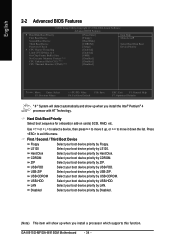
... device priority by ZIP. ZIP Select your boot device priority by Floppy. USB-CDROM Select your boot device priority by CDROM. GA-8I915G-MF/GA-8I915GM Motherboard - 34 - English 2-2 Advanced BIOS Features CMOS Setup Utility-Copyright (C) 1984-2004 Award Software Advanced BIOS Features `..., RAID, etc. USB-HDD Select your boot device priority by LS120. to 3 On-Chip Frame Buffer Size No-Execute Memory Protect (Note) CPU Enhanced Halt (C1E) (Note) CPU Thermal Monitor 2(TM2) (Note) [Press Enter] [Floppy] [Hard Disk] [CDROM] [Setup] [Enabled] [Enabled] [8MB] [Disabled] ...
... device priority by ZIP. ZIP Select your boot device priority by Floppy. USB-CDROM Select your boot device priority by CDROM. GA-8I915G-MF/GA-8I915GM Motherboard - 34 - English 2-2 Advanced BIOS Features CMOS Setup Utility-Copyright (C) 1984-2004 Award Software Advanced BIOS Features `..., RAID, etc. USB-HDD Select your boot device priority by LS120. to 3 On-Chip Frame Buffer Size No-Execute Memory Protect (Note) CPU Enhanced Halt (C1E) (Note) CPU Thermal Monitor 2(TM2) (Note) [Press Enter] [Floppy] [Hard Disk] [CDROM] [Setup] [Enabled] [Enabled] [8MB] [Disabled] ...

Manual
Page 42
... change depending on the actual CPU temperature. CPU Warning Temperature 60oC / 140oF Monitor CPU temperature at 60oC / 140oF. 70oC / 158oF Monitor CPU temperature at 70oC / 158oF. 80oC / 176oF Monitor CPU temperature at 80oC / 176oF. 90oC / 194oF Monitor CPU temperature at full speed. Current CPU Temperature Detect CPU temperature automatically. GA-8I915G-MF/GA-8I915GM Motherboard - 42 - Enable the CPU Smart FAN Control function...
... change depending on the actual CPU temperature. CPU Warning Temperature 60oC / 140oF Monitor CPU temperature at 60oC / 140oF. 70oC / 158oF Monitor CPU temperature at 70oC / 158oF. 80oC / 176oF Monitor CPU temperature at 80oC / 176oF. 90oC / 194oF Monitor CPU temperature at full speed. Current CPU Temperature Detect CPU temperature automatically. GA-8I915G-MF/GA-8I915GM Motherboard - 42 - Enable the CPU Smart FAN Control function...
Manual
Page 52
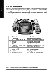
...CPU and Memory, 3) Smart-Fan control for managing fan speed control of CPU frequency 8. Display screen Display panel of both CPU cooling fan and North-Bridge Chipset cooling fan, 4) PC health for enhancing system performance, 2) C.I .B./2 setting page 3. GA-8I915G-MF/GA-... User Interface Overview Button / Display Description 1. C.I.A./C.I.A.2 and M.I.B./M.I.B.2 Enters the C.I.A./2 and M.I .A. Featuring several powerful yet easy to GIGABYTE website 10. "Easy Mode" & "Advance Mode" Toggles between Easy and Advance Mode 7. Function display LEDs Shows the current functions...
...CPU and Memory, 3) Smart-Fan control for managing fan speed control of CPU frequency 8. Display screen Display panel of both CPU cooling fan and North-Bridge Chipset cooling fan, 4) PC health for enhancing system performance, 2) C.I .B./2 setting page 3. GA-8I915G-MF/GA-... User Interface Overview Button / Display Description 1. C.I.A./C.I.A.2 and M.I.B./M.I.B.2 Enters the C.I.A./2 and M.I .A. Featuring several powerful yet easy to GIGABYTE website 10. "Easy Mode" & "Advance Mode" Toggles between Easy and Advance Mode 7. Function display LEDs Shows the current functions...


