Manual
Page 10
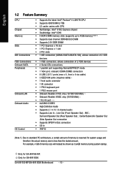
.../533MHz FSB Š L2 cache varies with CPU Š Northbridge: Intel® 915G Express chipset Š Southbridge: Intel® ICH6 Š 4 DDR DIMM memory slots (supports up to standard PC architecture, a certain amount of memory size will instead be shown as 3.xxGB memory during system startup. MIC ; GA-8I915G-MF/GA-8I915GM Motherboard - 10 - Only for...
.../533MHz FSB Š L2 cache varies with CPU Š Northbridge: Intel® 915G Express chipset Š Southbridge: Intel® ICH6 Š 4 DDR DIMM memory slots (supports up to standard PC architecture, a certain amount of memory size will instead be shown as 3.xxGB memory during system startup. MIC ; GA-8I915G-MF/GA-8I915GM Motherboard - 10 - Only for...
Manual
Page 12
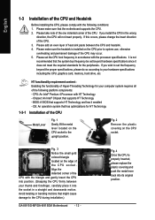
...supports HT Technology - Fig. 4 Once the CPU is installed on the CPU socket. English 1-3 Installation of the CPU and Heatsink Before installing the CPU, please comply with the processor specifications. Fig. 3 Notice the small gold colored triangle located on the CPU socket to the CPU during installation.) GA-8I915G-MF/GA...-8I915GM Motherboard - 12 - Please add an even layer of the CPU socket. Chipset: An Intel® Chipset that might cause damage to...
...supports HT Technology - Fig. 4 Once the CPU is installed on the CPU socket. English 1-3 Installation of the CPU and Heatsink Before installing the CPU, please comply with the processor specifications. Fig. 3 Notice the small gold colored triangle located on the CPU socket to the CPU during installation.) GA-8I915G-MF/GA...-8I915GM Motherboard - 12 - Please add an even layer of the CPU socket. Chipset: An Intel® Chipset that might cause damage to...
Manual
Page 20
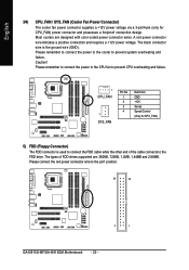
...connect the power to the cooler to the pin1 position. 34 33 2 1 GA-8I915G-MF/GA-8I915GM Motherboard - 20 - Please remember to connect the power to the CPU fan to the FDD drive. The types of the cable connects to prevent CPU overheating and failure. 1 CPU_FAN 1 SYS_FAN Pin No. 1 2 3 4 ...Definition GND +12V Sense Speed Control (Only for CPU_FAN) power connector and possesses a foolproof connection design. The black connector wire is used to connect the FDD cable while the other end of FDD drives supported ...
...connect the power to the cooler to the pin1 position. 34 33 2 1 GA-8I915G-MF/GA-8I915GM Motherboard - 20 - Please remember to connect the power to the CPU fan to the FDD drive. The types of the cable connects to prevent CPU overheating and failure. 1 CPU_FAN 1 SYS_FAN Pin No. 1 2 3 4 ...Definition GND +12V Sense Speed Control (Only for CPU_FAN) power connector and possesses a foolproof connection design. The black connector wire is used to connect the FDD cable while the other end of FDD drives supported ...
Manual
Page 34
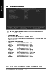
..., then press to move it down the list. Press to exit this function. GA-8I915G-MF/GA-8I915GM Motherboard - 34 - to move it up, or to 3 On-Chip Frame Buffer Size No-Execute Memory Protect (Note) CPU Enhanced Halt (C1E) (Note) CPU Thermal Monitor 2(TM2) (Note) [Press Enter] [Floppy] [Hard Disk] [... your boot device priority by Disabled. (Note) This item will detect automatically and show up when you install a processor which supports this menu. Disabled Select your boot device priority by USB-FDD. LS120 Select your boot device priority by LS120. USB-HDD Select...
..., then press to move it down the list. Press to exit this function. GA-8I915G-MF/GA-8I915GM Motherboard - 34 - to move it up, or to 3 On-Chip Frame Buffer Size No-Execute Memory Protect (Note) CPU Enhanced Halt (C1E) (Note) CPU Thermal Monitor 2(TM2) (Note) [Press Enter] [Floppy] [Hard Disk] [... your boot device priority by Disabled. (Note) This item will detect automatically and show up when you install a processor which supports this menu. Disabled Select your boot device priority by USB-FDD. LS120 Select your boot device priority by LS120. USB-HDD Select...

