Manual
Page 1
GA-8I915G-MF GA-8I915GM Intel® Pentium® 4 LGA775 Processor Motherboard User's Manual Rev. 2204 12ME-8I915GMF-2204 * The WEEE marking on the product indicates this product must not be disposed of with user's other household waste and must be handed over to a designated collection point for the recycling of waste electrical and electronic equipment!! * The WEEE marking applies only in European Union's member states.
GA-8I915G-MF GA-8I915GM Intel® Pentium® 4 LGA775 Processor Motherboard User's Manual Rev. 2204 12ME-8I915GMF-2204 * The WEEE marking on the product indicates this product must not be disposed of with user's other household waste and must be handed over to a designated collection point for the recycling of waste electrical and electronic equipment!! * The WEEE marking applies only in European Union's member states.
Manual
Page 2
Motherboard GA-8I915G-MF Jun. 11, 2004 Motherboard GA-8I915G-MF Jun. 11, 2004
Motherboard GA-8I915G-MF Jun. 11, 2004 Motherboard GA-8I915G-MF Jun. 11, 2004
Manual
Page 4
Table of Content GA-8I915G-MF Motherboard Layout 6 Block Diagram ...7 Chapter 1 Hardware Installation 9 1-1 Considerations Prior to Installation 9 1-2 Feature Summary 10 1-3 Installation of the CPU and Heatsink 12 1-3-1 Installation of the CPU 12 1-3-2 ...
Table of Content GA-8I915G-MF Motherboard Layout 6 Block Diagram ...7 Chapter 1 Hardware Installation 9 1-1 Considerations Prior to Installation 9 1-2 Feature Summary 10 1-3 Installation of the CPU and Heatsink 12 1-3-1 Installation of the CPU 12 1-3-2 ...
Manual
Page 6
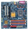
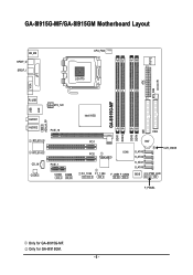
GA-8I915G-MF/GA-8I915GM Motherboard Layout IT8712 KB_MS SPDIF_O SPDIF_I CPU_FAN LGA775 SYS_FAN IR ATX VGA LPT R_USB ATX_12V USB LAN AZALIA_FP AUDIO1 AUDIO2 PCIE_16 RTL8110S RTL8100C CD_IN CODEC PCIE_1 COMA COMB GA-8I915G-MF DDR1 DDR2 Intel 915G IDE FDD DDR3 DDR4 PCI1 PCI2 ICH6 TSB43AB23 F2_1394 F1_1394 F_USB1 F_USB2 BAT S_ATA3 S_ATA2 S_ATA1 S_ATA0 CLR_CMOS BIOS PWR_LED F_PANEL Only for GA-8I915GM. - 6 - Only for GA-8I915G-MF.
GA-8I915G-MF/GA-8I915GM Motherboard Layout IT8712 KB_MS SPDIF_O SPDIF_I CPU_FAN LGA775 SYS_FAN IR ATX VGA LPT R_USB ATX_12V USB LAN AZALIA_FP AUDIO1 AUDIO2 PCIE_16 RTL8110S RTL8100C CD_IN CODEC PCIE_1 COMA COMB GA-8I915G-MF DDR1 DDR2 Intel 915G IDE FDD DDR3 DDR4 PCI1 PCI2 ICH6 TSB43AB23 F2_1394 F1_1394 F_USB1 F_USB2 BAT S_ATA3 S_ATA2 S_ATA1 S_ATA0 CLR_CMOS BIOS PWR_LED F_PANEL Only for GA-8I915GM. - 6 - Only for GA-8I915G-MF.
Manual
Page 10
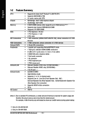
... reserved for system usage and therefore the actual memory size is less than the stated amount. Only for GA-8I915G-MF. Line Out (Front Speaker Out) ; Surround Speaker Out (Rear Speaker Out) ; GA-8I915G-MF/GA-8I915GM Motherboard - 10 - Only for GA-8I915GM. MIC ; English 1-2 Feature Summary CPU Chipset Memory Slots IDE Connections FDD Connections Onboard SATA Peripherals Onboard...
... reserved for system usage and therefore the actual memory size is less than the stated amount. Only for GA-8I915G-MF. Line Out (Front Speaker Out) ; Surround Speaker Out (Rear Speaker Out) ; GA-8I915G-MF/GA-8I915GM Motherboard - 10 - Only for GA-8I915GM. MIC ; English 1-2 Feature Summary CPU Chipset Memory Slots IDE Connections FDD Connections Onboard SATA Peripherals Onboard...
Manual
Page 12
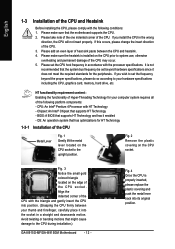
...Lever Fig. 1 Gently lift the metal lever located on the edge of the CPU socket. Avoid twisting or bending motions that the motherboard supports the CPU. 2. If you wish to set beyond the proper specifications, please do so according to the upright position. Please add...your thumb and forefinger, carefully place it enabled - Fig. 2 Remove the plastic covering on the CPU prior to the CPU during installation.) GA-8I915G-MF/GA-8I915GM Motherboard - 12 - Align the indented corner of the CPU with the following platform components: - Please make sure that might cause damage to system...
...Lever Fig. 1 Gently lift the metal lever located on the edge of the CPU socket. Avoid twisting or bending motions that the motherboard supports the CPU. 2. If you wish to set beyond the proper specifications, please do so according to the upright position. Please add...your thumb and forefinger, carefully place it enabled - Fig. 2 Remove the plastic covering on the CPU prior to the CPU during installation.) GA-8I915G-MF/GA-8I915GM Motherboard - 12 - Align the indented corner of the CPU with the following platform components: - Please make sure that might cause damage to system...
Manual
Page 14
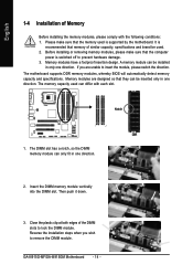
...in one direction. 2. Reverse the installation steps when you are designed so that the computer power is supported by the motherboard. GA-8I915G-MF/GA-8I915GM Motherboard - 14 - Before installing or removing memory modules, please make sure that memory of similar capacity, specifications and brand be... installed in only one direction. If you wish to lock the DIMM module. The motherboard supports DDR memory modules, whereby BIOS will automatically detect memory capacity and specifications. Then push it down. 3. English 1-4 ...
...in one direction. 2. Reverse the installation steps when you are designed so that the computer power is supported by the motherboard. GA-8I915G-MF/GA-8I915GM Motherboard - 14 - Before installing or removing memory modules, please make sure that memory of similar capacity, specifications and brand be... installed in only one direction. If you wish to lock the DIMM module. The motherboard supports DDR memory modules, whereby BIOS will automatically detect memory capacity and specifications. Then push it down. 3. English 1-4 ...
Manual
Page 16
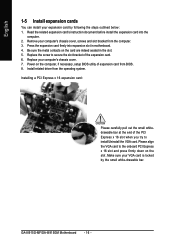
... the computer. 3. Please align the VGA card to the onboard PCI Express x 16 slot and press firmly down on the card are indeed seated in motherboard. 4. Read the related expansion card's instruction document before install the expansion card into expansion slot in the slot. 5. Press the expansion card firmly into the... bar at the end of the PCI Express x 16 slot when you try to secure the slot bracket of expansion card from the operating system. GA-8I915G-MF/GA-8I915GM Motherboard - 16 -
... the computer. 3. Please align the VGA card to the onboard PCI Express x 16 slot and press firmly down on the card are indeed seated in motherboard. 4. Read the related expansion card's instruction document before install the expansion card into expansion slot in the slot. 5. Press the expansion card firmly into the... bar at the end of the PCI Express x 16 slot when you try to secure the slot bracket of expansion card from the operating system. GA-8I915G-MF/GA-8I915GM Motherboard - 16 -
Manual
Page 18
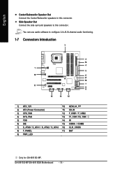
GA-8I915G-MF/GA-8I915GM Motherboard - 18 - English Center/Subwoofer Speaker Out Connect the Center/Subwoofer speakers to this connector. Side Speaker Out Connect the side surround speakers to configure 2-/4-/6-/8-channel ...) F_USB1 / F_USB2 4) SYS_FAN 13) F1_1394 / F2_1394 5) FDD 14) IR 6) IDE 15) COMA / COMB 7) S_ATA0 / S_ATA1 / S_ATA2 / S_ATA3 16) CLR_CMOS 8) F_PANEL 17) BAT 9) PWR_LED Only for GA-8I915G-MF. You can use audio software to this connector.
GA-8I915G-MF/GA-8I915GM Motherboard - 18 - English Center/Subwoofer Speaker Out Connect the Center/Subwoofer speakers to this connector. Side Speaker Out Connect the side surround speakers to configure 2-/4-/6-/8-channel ...) F_USB1 / F_USB2 4) SYS_FAN 13) F1_1394 / F2_1394 5) FDD 14) IR 6) IDE 15) COMA / COMB 7) S_ATA0 / S_ATA1 / S_ATA2 / S_ATA3 16) CLR_CMOS 8) F_PANEL 17) BAT 9) PWR_LED Only for GA-8I915G-MF. You can use audio software to this connector.
Manual
Page 20
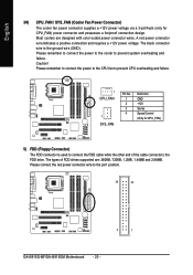
... CPU_FAN) 5) FDD (Floppy Connector) The FDD connector is the ground wire (GND). Please connect the red power connector wire to the pin1 position. 34 33 2 1 GA-8I915G-MF/GA-8I915GM Motherboard - 20 -
... CPU_FAN) 5) FDD (Floppy Connector) The FDD connector is the ground wire (GND). Please connect the red power connector wire to the pin1 position. 34 33 2 1 GA-8I915G-MF/GA-8I915GM Motherboard - 20 -
Manual
Page 22
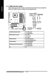
Pin 3: NC Pin 4: Data(-) Open: Normal Operation Close: Reset Hardware System Open: Normal Operation Close: Power On/Off Pin 1: LED anode(+) Pin 2: LED cathode(-) NC GA-8I915G-MF/GA-8I915GM Motherboard - 22 - English 8) F_PANEL (Front Panel Jumper) Please connect the power LED, PC peaker, reset switch and power switch etc of your chassis front panel to...
Pin 3: NC Pin 4: Data(-) Open: Normal Operation Close: Reset Hardware System Open: Normal Operation Close: Power On/Off Pin 1: LED anode(+) Pin 2: LED cathode(-) NC GA-8I915G-MF/GA-8I915GM Motherboard - 22 - English 8) F_PANEL (Front Panel Jumper) Please connect the power LED, PC peaker, reset switch and power switch etc of your chassis front panel to...
Manual
Page 24
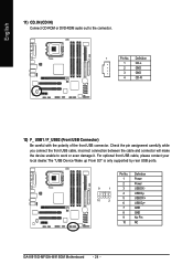
... polarity of the front USB connector. Definition 1 Power 2 Power 9 1 3 USB DX- 4 USB Dy- 10 2 5 USB DX+ 6 USB Dy+ 7 GND 8 GND 9 No Pin 10 NC GA-8I915G-MF/GA-8I915GM Motherboard - 24 - Check the pin assignment carefully while you connect the front USB cable, incorrect connection between the cable and connector will make the device unable...
... polarity of the front USB connector. Definition 1 Power 2 Power 9 1 3 USB DX- 4 USB Dy- 10 2 5 USB DX+ 6 USB Dy+ 7 GND 8 GND 9 No Pin 10 NC GA-8I915G-MF/GA-8I915GM Motherboard - 24 - Check the pin assignment carefully while you connect the front USB cable, incorrect connection between the cable and connector will make the device unable...
Manual
Page 26
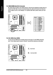
... cable, incorrect connection between the cable and connector will make the device unable to its default values by this jumper. 1 Open: Normal 1 Short :Clear CMOS GA-8I915G-MF/GA-8I915GM Motherboard - 26 - For optional COM cable, please contact your local dealer. 2 10 1 9 Pin No. 1 2 3 4 5 6 7 8 9 10 Definition NDCD A/BNSIN A/B NSOUT A/B NDTR A/BGND NDSR A/BNRTS A/BNCTS A/BNRI...
... cable, incorrect connection between the cable and connector will make the device unable to its default values by this jumper. 1 Open: Normal 1 Short :Clear CMOS GA-8I915G-MF/GA-8I915GM Motherboard - 26 - For optional COM cable, please contact your local dealer. 2 10 1 9 Pin No. 1 2 3 4 5 6 7 8 9 10 Definition NDCD A/BNSIN A/B NSOUT A/B NDTR A/BGND NDSR A/BNRTS A/BNCTS A/BNRI...
Manual
Page 30
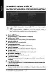
... system parameters which the system would be in the BIOS when somehow the system works not stable as figure below) will appear on the screen. GA-8I915G-MF/GA-8I915GM Motherboard - 30 - If you can't find the setting you to limit access to the system and Setup, or just to accept or enter the sub...
... system parameters which the system would be in the BIOS when somehow the system works not stable as figure below) will appear on the screen. GA-8I915G-MF/GA-8I915GM Motherboard - 30 - If you can't find the setting you to limit access to the system and Setup, or just to accept or enter the sub...
Manual
Page 32
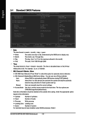
... Mode Use this if no IDE devices are : CHS/LBA/Large/Auto(default:Auto) Hard drive information should be labeled on the outside drive casing. GA-8I915G-MF/GA-8I915GM Motherboard - 32 - to Dec. Week The week, from 1999 through 2098 Time The times format in . Day The day, from 1 to 31 (or the maximum...
... Mode Use this if no IDE devices are : CHS/LBA/Large/Auto(default:Auto) Hard drive information should be labeled on the outside drive casing. GA-8I915G-MF/GA-8I915GM Motherboard - 32 - to Dec. Week The week, from 1999 through 2098 Time The times format in . Day The day, from 1 to 31 (or the maximum...
Manual
Page 34
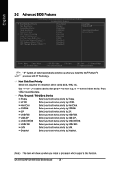
... Software Advanced BIOS Features ` Hard Disk Boot Priority First Boot Device Second Boot Device Third Boot Device Password Check # CPU Hyper-Threading Limit CPUID Max. GA-8I915G-MF/GA-8I915GM Motherboard - 34 - to 3 On-Chip Frame Buffer Size No-Execute Memory Protect (Note) CPU Enhanced Halt (C1E) (Note) CPU Thermal Monitor 2(TM2) (Note) [Press Enter...
... Software Advanced BIOS Features ` Hard Disk Boot Priority First Boot Device Second Boot Device Third Boot Device Password Check # CPU Hyper-Threading Limit CPUID Max. GA-8I915G-MF/GA-8I915GM Motherboard - 34 - to 3 On-Chip Frame Buffer Size No-Execute Memory Protect (Note) CPU Enhanced Halt (C1E) (Note) CPU Thermal Monitor 2(TM2) (Note) [Press Enter...
Manual
Page 36
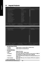
... will auto detect. (Default value) Set On-Chip SATA mode to Combined, you can use up to 6 HDDs to 4 HDDs on the motherboard; 2 for SATA and the other for GA-8I915G-MF. On-Chip SATA Mode Disabled Auto Combined Enhanced Non-Combined Disable this function. BIOS will be simulated to USB Controller USB 2.0 Controller...
... will auto detect. (Default value) Set On-Chip SATA mode to Combined, you can use up to 6 HDDs to 4 HDDs on the motherboard; 2 for SATA and the other for GA-8I915G-MF. On-Chip SATA Mode Disabled Auto Combined Enhanced Non-Combined Disable this function. BIOS will be simulated to USB Controller USB 2.0 Controller...
Manual
Page 38
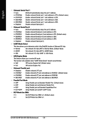
... onboard LPT port and address is 278/IRQ5. 3BC/IRQ7 Enable onboard LPT port and address is 2E8. Using Parallel port as Extended Capabilities Port. GA-8I915G-MF/GA-8I915GM Motherboard - 38 - Onboard Serial Port 2 Auto BIOS will automatically setup the port 2 address. 3F8/IRQ4 Enable onboard Serial port 2 and address is 3F8. 2F8/IRQ3...
... onboard LPT port and address is 278/IRQ5. 3BC/IRQ7 Enable onboard LPT port and address is 2E8. Using Parallel port as Extended Capabilities Port. GA-8I915G-MF/GA-8I915GM Motherboard - 38 - Onboard Serial Port 2 Auto BIOS will automatically setup the port 2 address. 3F8/IRQ4 Enable onboard Serial port 2 and address is 3F8. 2F8/IRQ3...
Manual
Page 40
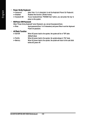
Enter Input password (from 1 to 5 characters to the Last state before AC-power off. GA-8I915G-MF/GA-8I915GM Motherboard - 40 - Disabled Keyboard 98 Disabled this function. (Default value) If your keyboard have "POWER Key" button, you can press the key to set the Keyboard ...
Enter Input password (from 1 to 5 characters to the Last state before AC-power off. GA-8I915G-MF/GA-8I915GM Motherboard - 40 - Disabled Keyboard 98 Disabled this function. (Default value) If your keyboard have "POWER Key" button, you can press the key to set the Keyboard ...

Manual
Page 42
... Control Disabled Enabled Disable this function. (Default value) CPU/SYSEM FAN Fail Warning Disabled Enabled Fan warning function disable. (Default value) Fan warning function enable. GA-8I915G-MF/GA-8I915GM Motherboard - 42 - When the CPU temperature is between 20 and 65 degrees Celsius, the CPU fan speed will stop spinning.
... Control Disabled Enabled Disable this function. (Default value) CPU/SYSEM FAN Fail Warning Disabled Enabled Fan warning function disable. (Default value) Fan warning function enable. GA-8I915G-MF/GA-8I915GM Motherboard - 42 - When the CPU temperature is between 20 and 65 degrees Celsius, the CPU fan speed will stop spinning.


