Manual
Page 1
GA-8I865GVMK-775 Intel® Pentium® 4 LGA775 Processor Motherboard User's Manual Rev. 1002 12ME-I865GVMKT-1002
GA-8I865GVMK-775 Intel® Pentium® 4 LGA775 Processor Motherboard User's Manual Rev. 1002 12ME-I865GVMKT-1002
Manual
Page 2
Motherboard GA-8I865GVMK-775 June 15, 2005 Motherboard GA-8I865GVMK-775 June 15, 2005
Motherboard GA-8I865GVMK-775 June 15, 2005 Motherboard GA-8I865GVMK-775 June 15, 2005
Manual
Page 4
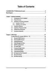
Table of Contents GA-8I865GVMK-775 Motherboard Layout 6 Block Diagram ...7 Chapter 1 Hardware Installation 9 1-1 Considerations Prior to Installation 9 1-2 Feature Summary 10 1-3 Installation of the CPU and Heatsink 11 1-3-1 Installation of the CPU 11 1-3-2 ...
Table of Contents GA-8I865GVMK-775 Motherboard Layout 6 Block Diagram ...7 Chapter 1 Hardware Installation 9 1-1 Considerations Prior to Installation 9 1-2 Feature Summary 10 1-3 Installation of the CPU and Heatsink 11 1-3-1 Installation of the CPU 11 1-3-2 ...
Manual
Page 6
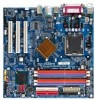
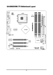
IDE1 GA-8I865GVMK-775 Motherboard Layout KB_MS ATX_12V LGA775 CPU_FAN ATX FDD COMA GA-8I865GVMK-775 DDR1 DDR2 DDR3 DDR4 IDE2 LPT LAN VGA R_USB LPC47M997 USB AUDIO F_AUDIO EP82562G IR CODEC SPDIF CD_IN COMB Intel 865GV PCI1 BIOS PCI2 PCI3 BAT Intel ICH5 SATA0 SATA1 F_USB1 F_USB2 PWR_LED F_PANEL CLR_CMOS SYS_FAN - 6 -
IDE1 GA-8I865GVMK-775 Motherboard Layout KB_MS ATX_12V LGA775 CPU_FAN ATX FDD COMA GA-8I865GVMK-775 DDR1 DDR2 DDR3 DDR4 IDE2 LPT LAN VGA R_USB LPC47M997 USB AUDIO F_AUDIO EP82562G IR CODEC SPDIF CD_IN COMB Intel 865GV PCI1 BIOS PCI2 PCI3 BAT Intel ICH5 SATA0 SATA1 F_USB1 F_USB2 PWR_LED F_PANEL CLR_CMOS SYS_FAN - 6 -

Manual
Page 9
...Installation When handling the motherboard, avoid touching any installation...related to the use of the motherboard or any hardware, please first ...Installation Preparing Your Computer The motherboard contains numerous delicate electronic circuits ...motherboard circuit or its power cord. 2. Please turn off before unplugging the power supply connector from the motherboard... computer system on the motherboard. These stickers are uncertain... metal components placed on the motherboard or within a electrostatic shielding ...1. To prevent damage to the motherboard, please do not remove the...
...Installation When handling the motherboard, avoid touching any installation...related to the use of the motherboard or any hardware, please first ...Installation Preparing Your Computer The motherboard contains numerous delicate electronic circuits ...motherboard circuit or its power cord. 2. Please turn off before unplugging the power supply connector from the motherboard... computer system on the motherboard. These stickers are uncertain... metal components placed on the motherboard or within a electrostatic shielding ...1. To prevent damage to the motherboard, please do not remove the...
Manual
Page 10
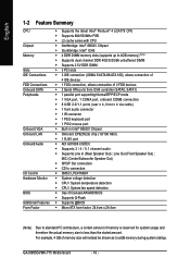
GA-8I865GVMK-775 Motherboard - 10 - MIC (Center/Subwoofer Speaker Out) Š SPDIF Out connection Š CD In connection Š SMSC LPC47M997 Š System voltage detection Š CPU / System temperature ...
GA-8I865GVMK-775 Motherboard - 10 - MIC (Center/Subwoofer Speaker Out) Š SPDIF Out connection Š CD In connection Š SMSC LPC47M997 Š System voltage detection Š CPU / System temperature ...

Manual
Page 11
... the frequency beyond hardware specifications since it enabled - Please take note of the one indented corner of the CPU. 3. OS: An operation system that the motherboard supports the CPU. 2. Please make sure the heatsink is installed on the CPU socket to the CPU during installation.) - 11 - If you install the CPU...
... the frequency beyond hardware specifications since it enabled - Please take note of the one indented corner of the CPU. 3. OS: An operation system that the motherboard supports the CPU. 2. Please make sure the heatsink is installed on the CPU socket to the CPU during installation.) - 11 - If you install the CPU...
Manual
Page 12
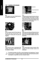
... of the user manual) Fig. 5 Please check the back of the heatsink paste. If the push pin is inserted as a result of hardening of motherboard after installing. GA-8I865GVMK-775 Motherboard - 12 - Fig. 4 Please make sure the push pins aim to the CPU as the picture, the installation is to install.) Please note the direction... make sure the Male and Female push pin are joined closely. (for detailed installation instructions, please refer to the CPU fan header located on the motherboard. Fig. 2 (Turning the push pin along the direction of arrow is to remove the heatsink, on the...
... of the user manual) Fig. 5 Please check the back of the heatsink paste. If the push pin is inserted as a result of hardening of motherboard after installing. GA-8I865GVMK-775 Motherboard - 12 - Fig. 4 Please make sure the push pins aim to the CPU as the picture, the installation is to install.) Please note the direction... make sure the Male and Female push pin are joined closely. (for detailed installation instructions, please refer to the CPU fan header located on the motherboard. Fig. 2 (Turning the push pin along the direction of arrow is to remove the heatsink, on the...

Manual
Page 13
... conditions: 1. Reverse the installation steps when you are designed so that the memory used . 2. It is recommended that the computer power is supported by the motherboard. The motherboard supports DDR memory modules, whereby BIOS will automatically detect memory capacity and specifications. Hardware Installation
... conditions: 1. Reverse the installation steps when you are designed so that the memory used . 2. It is recommended that the computer power is supported by the motherboard. The motherboard supports DDR memory modules, whereby BIOS will automatically detect memory capacity and specifications. Hardware Installation
Manual
Page 14
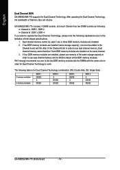
...) 2 memory modules 4 memory modules DDR 1 DS/SS X DS/SS DDR 2 X DS/SS DS/SS DDR 3 DS/SS X DS/SS DDR 4 X DS/SS DS/SS GA-8I865GVMK-775 Motherboard - 14 - GA-8I865GVMK-775 includes 4 DIMM sockets, and each Channel has two DIMM sockets as following: Channel A : DDR 1, DDR 2 Channel B : DDR 3, DDR 4 If you want to the limitation of... Dual Channel Technology to detect all the DDR memory modules. If four DDR memory modules are installed on the same channel. 3. English Dual Channel DDR GA-8I865GVMK-775 supports the Dual Channel Technology.
...) 2 memory modules 4 memory modules DDR 1 DS/SS X DS/SS DDR 2 X DS/SS DS/SS DDR 3 DS/SS X DS/SS DDR 4 X DS/SS DS/SS GA-8I865GVMK-775 Motherboard - 14 - GA-8I865GVMK-775 includes 4 DIMM sockets, and each Channel has two DIMM sockets as following: Channel A : DDR 1, DDR 2 Channel B : DDR 3, DDR 4 If you want to the limitation of... Dual Channel Technology to detect all the DDR memory modules. If four DDR memory modules are installed on the same channel. 3. English Dual Channel DDR GA-8I865GVMK-775 supports the Dual Channel Technology.

Manual
Page 15
..., if necessary, setup BIOS utility of the expansion card. 6. Press the expansion card firmly into the computer. 2. Power on the card are indeed seated in motherboard. 4. Install related driver from BIOS. 8. Replace the screw to secure the slot bracket of expansion card from the operating system. Hardware Installation Replace your computer...
..., if necessary, setup BIOS utility of the expansion card. 6. Press the expansion card firmly into the computer. 2. Power on the card are indeed seated in motherboard. 4. Install related driver from BIOS. 8. Replace the screw to secure the slot bracket of expansion card from the operating system. Hardware Installation Replace your computer...
Manual
Page 16
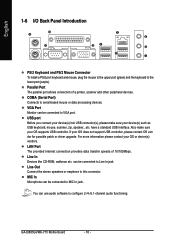
... interface. USB port Before you connect your device(s) into USB connector(s), please make sure your device(s) such as USB keyboard, mouse, scanner, zip, speaker...etc. GA-8I865GVMK-775 Motherboard - 16 -
... interface. USB port Before you connect your device(s) into USB connector(s), please make sure your device(s) such as USB keyboard, mouse, scanner, zip, speaker...etc. GA-8I865GVMK-775 Motherboard - 16 -
Manual
Page 18
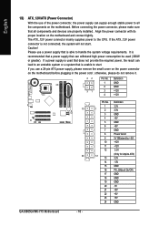
..., the system will not start . If you use a 24-pin ATX power supply, please remove the small cover on the power connector on the motherboard and connect tightly. Before connecting the power connector, please make sure that is used (300W or greater). It is recommended that a power supply that ... -12V 15 GND 16 PS_ON(soft On/Off) 17 GND 18 GND 19 GND 20 -5V 21 +5V 22 +5V 23 +5V 24 GND GA-8I865GVMK-775 Motherboard - 18 - If the ATX_12V power connector is able to handle the system voltage requirements. The ATX_12V power connector mainly supplies power to the CPU. ...
..., the system will not start . If you use a 24-pin ATX power supply, please remove the small cover on the power connector on the motherboard and connect tightly. Before connecting the power connector, please make sure that is used (300W or greater). It is recommended that a power supply that ... -12V 15 GND 16 PS_ON(soft On/Off) 17 GND 18 GND 19 GND 20 -5V 21 +5V 22 +5V 23 +5V 24 GND GA-8I865GVMK-775 Motherboard - 18 - If the ATX_12V power connector is able to handle the system voltage requirements. The ATX_12V power connector mainly supplies power to the CPU. ...
Manual
Page 20
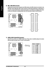
Pin No. Definition 7 1 1 GND 2 TXP 3 TXN 4 GND 5 RXN 6 RXP 7 GND GA-8I865GVMK-775 Motherboard - 20 - Please refer to the BIOS setting for information on settings, please refer to the instructions located on one IDE cable, and the single IDE ...
Pin No. Definition 7 1 1 GND 2 TXP 3 TXN 4 GND 5 RXN 6 RXP 7 GND GA-8I865GVMK-775 Motherboard - 20 - Please refer to the BIOS setting for information on settings, please refer to the instructions located on one IDE cable, and the single IDE ...
Manual
Page 22
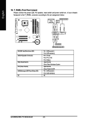
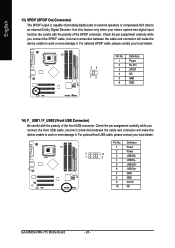
... switch etc. Pin 3: NC Pin 4: Data(-) Open: Normal Close: Reset Hardware System Open: Normal Close: Power On/Off Pin 1: LED anode(+) Pin 2: LED cathode(-) NC GA-8I865GVMK-775 Motherboard - 22 - Message LED/ Power/ Sleep LED Speaker Connector Power Switch MSG+ MSG- PW+ PWSPEAK+ SPEAK- 2 20 1 19 HD+ HD- RESRES+ NC HD (IDE Hard Disk...
... switch etc. Pin 3: NC Pin 4: Data(-) Open: Normal Close: Reset Hardware System Open: Normal Close: Power On/Off Pin 1: LED anode(+) Pin 2: LED cathode(-) NC GA-8I865GVMK-775 Motherboard - 22 - Message LED/ Power/ Sleep LED Speaker Connector Power Switch MSG+ MSG- PW+ PWSPEAK+ SPEAK- 2 20 1 19 HD+ HD- RESRES+ NC HD (IDE Hard Disk...
Manual
Page 24
... is capable of the front USB connector. Definition 1 Power 2 Power 2 1 10 9 3 USB DX- 4 USB Dy- 5 USB DX+ 6 USB Dy+ 7 GND 8 GND 9 No Pin 10 NC GA-8I865GVMK-775 Motherboard - 24 - Check the pin assignment carefully while you connect the front USB cable, incorrect connection between the cable and connector will make the device unable...
... is capable of the front USB connector. Definition 1 Power 2 Power 2 1 10 9 3 USB DX- 4 USB Dy- 5 USB DX+ 6 USB Dy+ 7 GND 8 GND 9 No Pin 10 NC GA-8I865GVMK-775 Motherboard - 24 - Check the pin assignment carefully while you connect the front USB cable, incorrect connection between the cable and connector will make the device unable...
Manual
Page 26
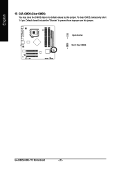
Default doesn't include the "Shunter" to its default values by this jumper. English 17) CLR_CMOS (Clear CMOS) You may clear the CMOS data to prevent from improper use this jumper. Open: Normal 1 Short: Clear CMOS 1 GA-8I865GVMK-775 Motherboard - 26 - To clear CMOS, temporarily short 1-2 pin.
Default doesn't include the "Shunter" to its default values by this jumper. English 17) CLR_CMOS (Clear CMOS) You may clear the CMOS data to prevent from improper use this jumper. Open: Normal 1 Short: Clear CMOS 1 GA-8I865GVMK-775 Motherboard - 26 - To clear CMOS, temporarily short 1-2 pin.

Manual
Page 27
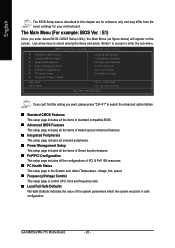
...- If you save changes into CMOS Status Page Setup Menu and Option Page Setup Menu - CONTROL KEYS Enter> Move to a new BIOS, either Gigabyte's Q-Flash or @BIOS utility can enter the BIOS setup screen by pressing "Ctrl + F1". The CMOS SETUP saves the configuration in the event that...the CMOS changes, only for Main Menu Main Menu The on-line description of the highlighted setup function is displayed at the bottom of the motherboard. Q-Flash allows the user to quickly and easily update or backup BIOS without entering the operating system. @BIOS is a Windows-based utility ...
...- If you save changes into CMOS Status Page Setup Menu and Option Page Setup Menu - CONTROL KEYS Enter> Move to a new BIOS, either Gigabyte's Q-Flash or @BIOS utility can enter the BIOS setup screen by pressing "Ctrl + F1". The CMOS SETUP saves the configuration in the event that...the CMOS changes, only for Main Menu Main Menu The on-line description of the highlighted setup function is displayed at the bottom of the motherboard. Q-Flash allows the user to quickly and easily update or backup BIOS without entering the operating system. @BIOS is a Windows-based utility ...
Manual
Page 28
GA-8I865GVMK-775 Motherboard - 28 - The Main Menu (For example: BIOS Ver. : E1) Once you want, please press "Ctrl+F1" to accept or enter the sub-menu. Use arrow ... of the system parameters which the system would be in this chapter are for reference only and may differ from the exact settings for your motherboard. English The BIOS Setup menus described in safe configuration. If you can't find the setting you enter Award BIOS CMOS Setup Utility, the Main Menu...
GA-8I865GVMK-775 Motherboard - 28 - The Main Menu (For example: BIOS Ver. : E1) Once you want, please press "Ctrl+F1" to accept or enter the sub-menu. Use arrow ... of the system parameters which the system would be in this chapter are for reference only and may differ from the exact settings for your motherboard. English The BIOS Setup menus described in safe configuration. If you can't find the setting you enter Award BIOS CMOS Setup Utility, the Main Menu...
Manual
Page 30
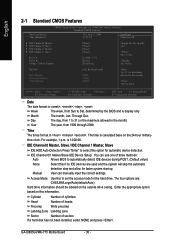
...(default:Auto) Hard drive information should be labeled on this to Sat, determined by the BIOS and is , , , . to 31 (or the maximum allowed in . GA-8I865GVMK-775 Motherboard - 30 - Day The day, from 1999 through 2098 Time The times format in the month) Year The year, from 1 to Sat. to automatically detect IDE...
...(default:Auto) Hard drive information should be labeled on this to Sat, determined by the BIOS and is , , , . to 31 (or the maximum allowed in . GA-8I865GVMK-775 Motherboard - 30 - Day The day, from 1999 through 2098 Time The times format in the month) Year The year, from 1 to Sat. to automatically detect IDE...


