Manual
Page 4
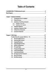
... the CPU 11 1-3-2 Installation of the Heatsink 12 1-4 Installation of Memory 13 1-5 Installation of Expansion Cards 15 1-6 I/O Back Panel Introduction 16 1-7 Connectors Introduction 17 Chapter 2 BIOS Setup 27 The Main Menu (For example: BIOS Ver. : E1 28 2-1 Standard CMOS Features 30 2-2 Advanced BIOS Features 32 2-3 IntegratedPeripherals 34 2-4 Power Management Setup 37 2-5 PnP/PCI Configurations 38 2-6 PC Health Status 39 2-7 Frequency/Voltage Control 40 2-8 Load Fail-Safe Defaults 41 2-9 Load Optimized Defaults 41 2-10 Set Supervisor/User Password 42 2-11 Save & Exit Setup...
... the CPU 11 1-3-2 Installation of the Heatsink 12 1-4 Installation of Memory 13 1-5 Installation of Expansion Cards 15 1-6 I/O Back Panel Introduction 16 1-7 Connectors Introduction 17 Chapter 2 BIOS Setup 27 The Main Menu (For example: BIOS Ver. : E1 28 2-1 Standard CMOS Features 30 2-2 Advanced BIOS Features 32 2-3 IntegratedPeripherals 34 2-4 Power Management Setup 37 2-5 PnP/PCI Configurations 38 2-6 PC Health Status 39 2-7 Frequency/Voltage Control 40 2-8 Load Fail-Safe Defaults 41 2-9 Load Optimized Defaults 41 2-10 Set Supervisor/User Password 42 2-11 Save & Exit Setup...
Manual
Page 10
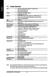
... CPU Chipset Memory Slots IDE Connections FDD Connections Onboard SATA Peripherals Onboard VGA Onboard LAN Onboard Audio I/O Control Hardware Monitor BIOS Additional Features Form Factor Š Supports the latest Intel® Pentium® 4 LGA775 CPU Š Supports 800/533MHz FSB Š L2 cache varies with CPU Š Northbridge: Intel® 865GV Chipset Š Southbridge: Intel® ICH5 Š 4 DDR DIMM memory slots (supports up to standard PC architecture, a certain amount of 2 FDD devices Š 2 Serial ATA ports from ICH5 controller...
... CPU Chipset Memory Slots IDE Connections FDD Connections Onboard SATA Peripherals Onboard VGA Onboard LAN Onboard Audio I/O Control Hardware Monitor BIOS Additional Features Form Factor Š Supports the latest Intel® Pentium® 4 LGA775 CPU Š Supports 800/533MHz FSB Š L2 cache varies with CPU Š Northbridge: Intel® 865GV Chipset Š Southbridge: Intel® ICH5 Š 4 DDR DIMM memory slots (supports up to standard PC architecture, a certain amount of 2 FDD devices Š 2 Serial ATA ports from ICH5 controller...
Manual
Page 12
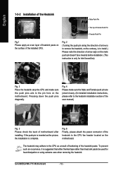
GA-8I865GVMK-775 Motherboard - 12 - Fig. 6 Finally, please attach the power connector of arrow sign on the male push pin doesn't face inwards before installation. (This instruction is suggested that either thermal tape rather than heat sink paste be used for detailed installation instructions, please refer to the CPU as the picture, the installation is to install.) Please note the direction of the heatsink to the pin hole...
GA-8I865GVMK-775 Motherboard - 12 - Fig. 6 Finally, please attach the power connector of arrow sign on the male push pin doesn't face inwards before installation. (This instruction is suggested that either thermal tape rather than heat sink paste be used for detailed installation instructions, please refer to the CPU as the picture, the installation is to install.) Please note the direction of the heatsink to the pin hole...
Manual
Page 16
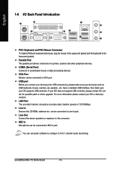
... Connector To install a PS/2 port keyboard and mouse, plug the mouse to the upper port (green) and the keyboard to serial-based mouse or data processing devices. For more information please contact your OS does not support USB controller, please contact OS ven dor for possible patch or driver upgrade. GA-8I865GVMK-775 Motherboard - 16 - Line Out Connect the stereo speakers or earphone to configure 2-/4-/5.1-channel audio functioning. Parallel Port The parallel port allows connection of...
... Connector To install a PS/2 port keyboard and mouse, plug the mouse to the upper port (green) and the keyboard to serial-based mouse or data processing devices. For more information please contact your OS does not support USB controller, please contact OS ven dor for possible patch or driver upgrade. GA-8I865GVMK-775 Motherboard - 16 - Line Out Connect the stereo speakers or earphone to configure 2-/4-/5.1-channel audio functioning. Parallel Port The parallel port allows connection of...
Manual
Page 20
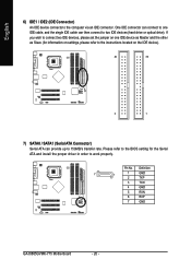
... the BIOS setting for information on settings, please refer to the instructions located on one IDE cable, and the single IDE cable can connect to one IDE device as Master and the other as Slave (for the Serial ATA and install the proper driver in order to the computer via an IDE connector. English 6) IDE1 / IDE2 (IDE Connector) An IDE device connects to work properly. Definition 7 1 1 GND 2 TXP 3 TXN 4 GND 5 RXN 6 RXP 7 GND GA-8I865GVMK-775 Motherboard...
... the BIOS setting for information on settings, please refer to the instructions located on one IDE cable, and the single IDE cable can connect to one IDE device as Master and the other as Slave (for the Serial ATA and install the proper driver in order to the computer via an IDE connector. English 6) IDE1 / IDE2 (IDE Connector) An IDE device connects to work properly. Definition 7 1 1 GND 2 TXP 3 TXN 4 GND 5 RXN 6 RXP 7 GND GA-8I865GVMK-775 Motherboard...
Manual
Page 22
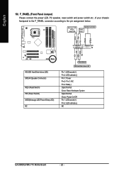
... (IDE Hard Disk Active LED) SPEAK (Speaker Connector) RES (Reset Switch) PW (Power Switch) MSG(Message LED/Power/Sleep LED) NC Reset Switch IDE Hard Disk Active LED Pin 1: LED anode(+) Pin 2: LED cathode(-) Pin 1: Power Pin 2- of your chassis frontpanel to the F_PANEL connector according to the pin assignment below. Pin 3: NC Pin 4: Data(-) Open: Normal Close: Reset Hardware System Open: Normal Close: Power On/Off Pin 1: LED anode(+) Pin 2: LED cathode(-) NC GA-8I865GVMK-775 Motherboard - 22 - English 10) F_PANEL (Front Panel Jumper) Please connect the power LED, PC speaker, reset switch...
... (IDE Hard Disk Active LED) SPEAK (Speaker Connector) RES (Reset Switch) PW (Power Switch) MSG(Message LED/Power/Sleep LED) NC Reset Switch IDE Hard Disk Active LED Pin 1: LED anode(+) Pin 2: LED cathode(-) Pin 1: Power Pin 2- of your chassis frontpanel to the F_PANEL connector according to the pin assignment below. Pin 3: NC Pin 4: Data(-) Open: Normal Close: Reset Hardware System Open: Normal Close: Power On/Off Pin 1: LED anode(+) Pin 2: LED cathode(-) NC GA-8I865GVMK-775 Motherboard - 22 - English 10) F_PANEL (Front Panel Jumper) Please connect the power LED, PC speaker, reset switch...
Manual
Page 28
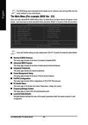
... find the setting you enter Award BIOS CMOS Setup Utility, the Main Menu (as figure below) will appear on the screen. CMOS Setup Utility-Copyright (C) 1984-2005 Award Software ` Standard CMOS Features ` Advanced BIOS Features ` Integrated Peripherals ` Power Management Setup ` PnP/PCI Configurations ` PC Health Status ` Frequency/Voltage Control ESC: Quit F8: Q-Flash Load Fail-Safe Defaults Load Optimized Defaults Set Supervisor Password Set User Password Save & Exit Setup Exit Without Saving KLJI: Select Item F10: Save & Exit Setup Time, Date, Hard Disk Type... Use arrow keys to select...
... find the setting you enter Award BIOS CMOS Setup Utility, the Main Menu (as figure below) will appear on the screen. CMOS Setup Utility-Copyright (C) 1984-2005 Award Software ` Standard CMOS Features ` Advanced BIOS Features ` Integrated Peripherals ` Power Management Setup ` PnP/PCI Configurations ` PC Health Status ` Frequency/Voltage Control ESC: Quit F8: Q-Flash Load Fail-Safe Defaults Load Optimized Defaults Set Supervisor Password Set User Password Save & Exit Setup Exit Without Saving KLJI: Select Item F10: Save & Exit Setup Time, Date, Hard Disk Type... Use arrow keys to select...
Manual
Page 30
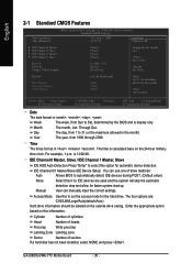
... Help Menu Level` ` IDE Channel 0 Master ` IDE Channel 0 Slave ` IDE Channel 1 Master ` IDE Channel 1 Slave Drive A Drive B Floppy 3 Mode Support [None] [None] [None] [None] [1.44M, 3.5"] [None] [Disabled] Change the day, month, year Sun. to Dec. Through Dec. Manual User can use one of sectors If a hard disk has not been installed, select NONE and press . The four options are used and the system will skip the automatic detection step and allow for the hard drive. GA-8I865GVMK-775 Motherboard - 30 - IDE Channel...
... Help Menu Level` ` IDE Channel 0 Master ` IDE Channel 0 Slave ` IDE Channel 1 Master ` IDE Channel 1 Slave Drive A Drive B Floppy 3 Mode Support [None] [None] [None] [None] [1.44M, 3.5"] [None] [Disabled] Change the day, month, year Sun. to Dec. Through Dec. Manual User can use one of sectors If a hard disk has not been installed, select NONE and press . The four options are used and the system will skip the automatic detection step and allow for the hard drive. GA-8I865GVMK-775 Motherboard - 30 - IDE Channel...
Manual
Page 32
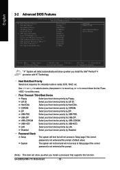
... not entered at the prompt. (Default value) The system will not boot and will not access to move it down the list. English 2-2 Advanced BIOS Features CMOS Setup Utility-Copyright (C) 1984-2005 Award Software Advanced BIOS Features ` Hard Disk Boot Priority First Boot Device Second Boot Device Third Boot Device Password Check # CPU Hyper-Threading Limit CPUID Max. Hard Disk Boot Priority Select boot sequence for onboard(or add-on cards) SCSI, RAID, etc. First / Second / Third Boot Device Floppy Select your boot device priority by USB...
... not entered at the prompt. (Default value) The system will not boot and will not access to move it down the list. English 2-2 Advanced BIOS Features CMOS Setup Utility-Copyright (C) 1984-2005 Award Software Advanced BIOS Features ` Hard Disk Boot Priority First Boot Device Second Boot Device Third Boot Device Password Check # CPU Hyper-Threading Limit CPUID Max. Hard Disk Boot Priority Select boot sequence for onboard(or add-on cards) SCSI, RAID, etc. First / Second / Third Boot Device Floppy Select your boot device priority by USB...
Manual
Page 34
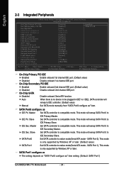
...CMOS Setup Utility-Copyright (C) 1984-2005 Award Software Integrated Peripherals On-Chip Primary PCI IDE On-Chip Secondary PCI IDE On-Chip SATA x SATA Port0 configure as SATA Port1 configure as IDE Pri. SATA Port0 configure as USB Controller USB 2.0 Controller USB Keyboard Support USB Mouse Support AC97 Audio Onboard H/W LAN Onboard LAN Boot ROM POWER ON Function Onboard Serial Port 1 Onboard Serial Port 2 UART Mode Select x UR2 Duplex Mode Onboard Parallel Port Parallel Port Mode x ECP Mode Use DMA [Enabled] [Enabled] [Auto] SATA Port0 SATA Port1 [Enabled] [Enabled] [Disabled] [Disabled...
...CMOS Setup Utility-Copyright (C) 1984-2005 Award Software Integrated Peripherals On-Chip Primary PCI IDE On-Chip Secondary PCI IDE On-Chip SATA x SATA Port0 configure as SATA Port1 configure as IDE Pri. SATA Port0 configure as USB Controller USB 2.0 Controller USB Keyboard Support USB Mouse Support AC97 Audio Onboard H/W LAN Onboard LAN Boot ROM POWER ON Function Onboard Serial Port 1 Onboard Serial Port 2 UART Mode Select x UR2 Duplex Mode Onboard Parallel Port Parallel Port Mode x ECP Mode Use DMA [Enabled] [Enabled] [Auto] SATA Port0 SATA Port1 [Enabled] [Enabled] [Disabled] [Disabled...
Manual
Page 39
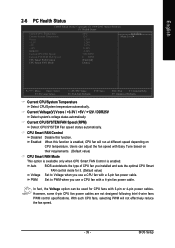
... Defaults Current CPU/System Temperature Detect CPU/System temperature automatically. CPU Smart FAN Control Disabled Disable this function is enabled. BIOS Setup Auto BIOS autodetects the type of CPU fan you installed and sets the optimal CPU Smart FAN control mode for CPU fans with a 3-pin fan power cable. However, some 4-pin CPU fan power cables are not designed following Intel 4-wire fans PWM control specifications. In fact, the Voltage option can adjust the fan speed with a 4-pin fan power cable. PWM Set to Voltage when you use a CPU fan with 3-pin or 4-pin power...
... Defaults Current CPU/System Temperature Detect CPU/System temperature automatically. CPU Smart FAN Control Disabled Disable this function is enabled. BIOS Setup Auto BIOS autodetects the type of CPU fan you installed and sets the optimal CPU Smart FAN control mode for CPU fans with a 3-pin fan power cable. However, some 4-pin CPU fan power cables are not designed following Intel 4-wire fans PWM control specifications. In fact, the Voltage option can adjust the fan speed with a 4-pin fan power cable. PWM Set to Voltage when you use a CPU fan with 3-pin or 4-pin power...
Manual
Page 42
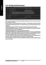
... When disabled, anyone may also press to enter password. Type the password again and press . GA-8I865GVMK-775 Motherboard - 42 - Type the password, up to specify two separate passwords: SUPERVISOR PASSWORD and a USER PASSWORD. English 2-10 Set Supervisor/User Password CMOS Setup Utility-Copyright (C) 1984-2005 Award Software ` Standard CMOS Features ` Advanced BIOS Features ` Integrated Peripherals ` Power Management Setup ` PnP/PCI ConfigurationEsnter Password: ` PC Health Status ` MB Intelligent Tweaker(M.I.T.) Load Fail-Safe Defaults Load Optimized Defaults Set Supervisor...
... When disabled, anyone may also press to enter password. Type the password again and press . GA-8I865GVMK-775 Motherboard - 42 - Type the password, up to specify two separate passwords: SUPERVISOR PASSWORD and a USER PASSWORD. English 2-10 Set Supervisor/User Password CMOS Setup Utility-Copyright (C) 1984-2005 Award Software ` Standard CMOS Features ` Advanced BIOS Features ` Integrated Peripherals ` Power Management Setup ` PnP/PCI ConfigurationEsnter Password: ` PC Health Status ` MB Intelligent Tweaker(M.I.T.) Load Fail-Safe Defaults Load Optimized Defaults Set Supervisor...
Manual
Page 49
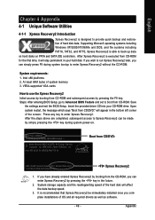
... system power-on PATA and SATA IDE controllers. System storage capacity and the reading/writing speed of system memory 3. Upon system restart, the message which says "Boot from CD/DVD: Award Modular BIOS v6.00PG, An Energy Star Ally Copyright (C) 1984-2005, Award Software, Inc. After Xpress Recovery2 is designed to run Xpress Recovery2 later, you can be immediately installed once you complete installations of hard disk...
... system power-on PATA and SATA IDE controllers. System storage capacity and the reading/writing speed of system memory 3. Upon system restart, the message which says "Boot from CD/DVD: Award Modular BIOS v6.00PG, An Energy Star Ally Copyright (C) 1984-2005, Award Software, Inc. After Xpress Recovery2 is designed to run Xpress Recovery2 later, you can be immediately installed once you complete installations of hard disk...
Manual
Page 52
...Blocking a task and pressing Enter key on your keyboard to operate the Q-Flash/Dual BIOS utility. CMOS Setup Utility-Copyright (C) 1984-2004 Award Software Standard CMOS Features Advanced BIOS Features Integrated Peripherals Power Management Setup PnP/PCI Configurations PC Health Status MB Intelligent Tweaker(M.I.T.) ESC: Quit F8: Dual BIOS/Q-Flash Select Language Load Fail-Safe Defaults Load Optimized Defaults Set Supervisor Password Set User Password Save & Exit Setup Exit Without Saving F3: Change Language F10: Save & Exit Setup Time, Date, Hard Disk Type... Action bar: Contains...
...Blocking a task and pressing Enter key on your keyboard to operate the Q-Flash/Dual BIOS utility. CMOS Setup Utility-Copyright (C) 1984-2004 Award Software Standard CMOS Features Advanced BIOS Features Integrated Peripherals Power Management Setup PnP/PCI Configurations PC Health Status MB Intelligent Tweaker(M.I.T.) ESC: Quit F8: Dual BIOS/Q-Flash Select Language Load Fail-Safe Defaults Load Optimized Defaults Set Supervisor Password Set User Password Save & Exit Setup Exit Without Saving F3: Change Language F10: Save & Exit Setup Time, Date, Hard Disk Type... Action bar: Contains...
Manual
Page 54
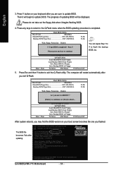
... may find the BIOS version on your boot screen becomes the one you flashed. Load Default Settings Save Settings to CMOS Q-Flash Utility Load Main BIOS from Floppy Load Backup BIOS from Floppy Save Main BIOS to Floppy Save Backup BIOS to Floppy Enter : Run :Move ESC:Reset F10:Power Off You can repeat Step 1 to 4 to enter SETUP / Dual BIOS / Q-Flash / F9 For Xpress Recovery 09/23/2003-i875P-6A79BG03C-00 GA-8I865GVMK-775 Motherboard - 54 - The BIOS file becomes Fab after you exit Q-Flash. Award Modular BIOS v6.00PG, An...
... may find the BIOS version on your boot screen becomes the one you flashed. Load Default Settings Save Settings to CMOS Q-Flash Utility Load Main BIOS from Floppy Load Backup BIOS from Floppy Save Main BIOS to Floppy Save Backup BIOS to Floppy Enter : Run :Move ESC:Reset F10:Power Off You can repeat Step 1 to 4 to enter SETUP / Dual BIOS / Q-Flash / F9 For Xpress Recovery 09/23/2003-i875P-6A79BG03C-00 GA-8I865GVMK-775 Motherboard - 54 - The BIOS file becomes Fab after you exit Q-Flash. Award Modular BIOS v6.00PG, An...
Manual
Page 55
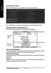
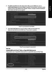
.... This part guides users of single-BIOS motherboards how to load defaults. 7. Part Two: Updating BIOS with Q-FlashTM Utility on your keyboard to update BIOS using the Q-FlashTM utility. Appendix Press Del to save the settings to CMOS and EXIT (SYe/tNS)u?pYervisor Password PnP/PCI Configurations Set User Password PC Health Status Save & Exit Setup MB Intelligent Tweaker(M.I.T.) Exit Without Saving ESC: Quit F8: Dual BIOS/Q-Flash F3: Change Language F10: Save & Exit Setup Time, Date, Hard Disk Type... Press Y on Single-BIOS Motherboards...
.... This part guides users of single-BIOS motherboards how to load defaults. 7. Part Two: Updating BIOS with Q-FlashTM Utility on your keyboard to update BIOS using the Q-FlashTM utility. Appendix Press Del to save the settings to CMOS and EXIT (SYe/tNS)u?pYervisor Password PnP/PCI Configurations Set User Password PC Health Status Save & Exit Setup MB Intelligent Tweaker(M.I.T.) Exit Without Saving ESC: Quit F8: Dual BIOS/Q-Flash F3: Change Language F10: Save & Exit Setup Time, Date, Hard Disk Type... Press Y on Single-BIOS Motherboards...
Manual
Page 58
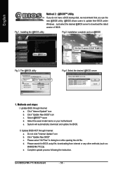
... desired @BIOS server to update their BIOS under Windows. Installing the @BIOS utility Fig 2. Update BIOS through Internet: a. Update BIOS NOT through Internet a. d. GA-8I865GVMK-775 Motherboard - 58 - Click Sart/ Programs/ GIGABYTE/@BIOS Fig 3. Select the exact model name on your motherboard e. Please select "All Files" in dialog box while opening the old file. Installation complete and run @BIOS Select @BIOS item. Click "Update New BIOS" icon c. Click "Internet Update" icon b. Please search for BIOS unzip file, downloading from internet...
... desired @BIOS server to update their BIOS under Windows. Installing the @BIOS utility Fig 2. Update BIOS through Internet: a. Update BIOS NOT through Internet a. d. GA-8I865GVMK-775 Motherboard - 58 - Click Sart/ Programs/ GIGABYTE/@BIOS Fig 3. Select the exact model name on your motherboard e. Please select "All Files" in dialog box while opening the old file. Installation complete and run @BIOS Select @BIOS item. Click "Update New BIOS" icon c. Click "Internet Update" icon b. Please search for BIOS unzip file, downloading from internet...
Manual
Page 61
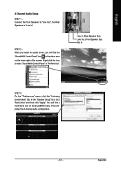
... English 4 Channel Audio Setup STEP 1 : Connect the Front Speakers to "Line Out", the Rear Speakers to select "SoundMAX Control Panel" or "Preferences". Line In (Rear Speaker Out) Line Out (Front Speaker Out) Mic In STEP 3: On the "Preferences" menu, click the "Listening Environment" tab. You will find a multi-driver icon on the lower right of the screen. STEP 2 : After you install the audio driver, you will...
... English 4 Channel Audio Setup STEP 1 : Connect the Front Speakers to "Line Out", the Rear Speakers to select "SoundMAX Control Panel" or "Preferences". Line In (Rear Speaker Out) Line Out (Front Speaker Out) Mic In STEP 3: On the "Preferences" menu, click the "Listening Environment" tab. You will find a multi-driver icon on the lower right of the screen. STEP 2 : After you install the audio driver, you will...
Manual
Page 62
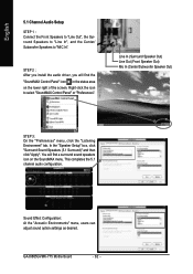
... (Center/Subwoofer Speaker Out) STEP 3: On the "Preferences" menu, click the "Listening Environment" tab. GA-8I865GVMK-775 Motherboard - 62 - Sound Effect Configuration: At the "Acoustic Environments" menu, users can adjust sound option settings as desired. STEP 2 : After you install the audio driver, you will find the "SoundMAX Control Panel" icon in the status area on the SoundMAX menu. You will find a surround sound speakers icon on the lower right of the screen.
... (Center/Subwoofer Speaker Out) STEP 3: On the "Preferences" menu, click the "Listening Environment" tab. GA-8I865GVMK-775 Motherboard - 62 - Sound Effect Configuration: At the "Acoustic Environments" menu, users can adjust sound option settings as desired. STEP 2 : After you install the audio driver, you will find the "SoundMAX Control Panel" icon in the status area on the SoundMAX menu. You will find a surround sound speakers icon on the lower right of the screen.
Manual
Page 64
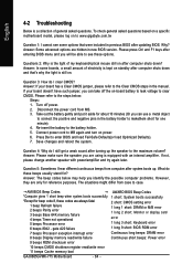
...and turn on power. 6. Answer: Please make sure the speaker you identify the possible computer problems. However, they are hidden in the manual. If not, please change another speaker with an internal amplifier. Answer: The beep codes below : Steps: 1. gate A20 failure 1 long 9 short: BIOS ROM error 7 beeps Processor exception interrupt error Continuous long beeps: DRAM error 8 beeps Display memory read/write failure Continuous short beeps: Power error 9 beeps ROM checksum error 10 beeps CMOS shutdown register read/write error 11 beeps Cache memory bad GA-8I865GVMK-775 Motherboard...
...and turn on power. 6. Answer: Please make sure the speaker you identify the possible computer problems. However, they are hidden in the manual. If not, please change another speaker with an internal amplifier. Answer: The beep codes below : Steps: 1. gate A20 failure 1 long 9 short: BIOS ROM error 7 beeps Processor exception interrupt error Continuous long beeps: DRAM error 8 beeps Display memory read/write failure Continuous short beeps: Power error 9 beeps ROM checksum error 10 beeps CMOS shutdown register read/write error 11 beeps Cache memory bad GA-8I865GVMK-775 Motherboard...


