
Manual
Page 3
...The revision number on your motherboard revision before updating motherboard BIOS, drivers, or when looking for technical information. Disclaimer Information in this manual may be made by GIGABYTE without GIGABYTE's prior written permission. No part of GIGABYTE. Check your motherboard looks like this manual may be ... is protected by any form or by copyright laws and is 1.0. Changes to the specifications and features in this product, GIGABYTE provides the following types of documentations: For quick set-up of this manual are legally registered to assist in ...
...The revision number on your motherboard revision before updating motherboard BIOS, drivers, or when looking for technical information. Disclaimer Information in this manual may be made by GIGABYTE without GIGABYTE's prior written permission. No part of GIGABYTE. Check your motherboard looks like this manual may be ... is protected by any form or by copyright laws and is 1.0. Changes to the specifications and features in this product, GIGABYTE provides the following types of documentations: For quick set-up of this manual are legally registered to assist in ...
Manual
Page 4
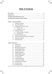
Table of Contents Box Contents...6 Optional Items...6 GA-880GA-UD3H Motherboard Layout 7 GA-880GA-UD3H Motherboard Block Diagram 8 Chapter 1 Hardware Installation 9 1-1 Installation Precautions 9 1-2 Product Specifications 10 1-3 Installing the CPU and CPU Cooler...8482; Configuration 19 1-7 Back Panel Connectors 20 1-8 Internal Connectors 23 Chapter 2 BIOS Setup 33 2-1 Startup Screen 34 2-2 The Main Menu 35 2-3 MB Intelligent Tweaker(M.I.T 37 2-4 Standard CMOS Features 44 2-5 Advanced BIOS Features 46 2-6 Integrated Peripherals 48 2-7 Power Management Setup 51 2-8 PnP/PCI ...
Table of Contents Box Contents...6 Optional Items...6 GA-880GA-UD3H Motherboard Layout 7 GA-880GA-UD3H Motherboard Block Diagram 8 Chapter 1 Hardware Installation 9 1-1 Installation Precautions 9 1-2 Product Specifications 10 1-3 Installing the CPU and CPU Cooler...8482; Configuration 19 1-7 Back Panel Connectors 20 1-8 Internal Connectors 23 Chapter 2 BIOS Setup 33 2-1 Startup Screen 34 2-2 The Main Menu 35 2-3 MB Intelligent Tweaker(M.I.T 37 2-4 Standard CMOS Features 44 2-5 Advanced BIOS Features 46 2-6 Integrated Peripherals 48 2-7 Power Management Setup 51 2-8 PnP/PCI ...

Manual
Page 5
...Download Center 62 3-7 New Utilities...62 Chapter 4 Unique Features 63 4-1 Xpress Recovery2 63 4-2 BIOS Update Utilities 66 4-2-1 Updating the BIOS with the Q-Flash Utility 66 4-2-2 Updating the BIOS with the @BIOS Utility 69 4-3 EasyTune 6...70 4-4 Easy Energy Saver 71 4-5 Q-Share...73 4-6 SMART ...Recovery 74 4-7 Auto Green...75 4-8 Cloud OC...76 Chapter 5 Appendix...77 5-1 Configuring SATA Hard Drive(s 77 5-1-1 Configuring AMD SB850 SATA Controller 77 5-1-2 Configuring GIGABYTE ...
...Download Center 62 3-7 New Utilities...62 Chapter 4 Unique Features 63 4-1 Xpress Recovery2 63 4-2 BIOS Update Utilities 66 4-2-1 Updating the BIOS with the Q-Flash Utility 66 4-2-2 Updating the BIOS with the @BIOS Utility 69 4-3 EasyTune 6...70 4-4 Easy Energy Saver 71 4-5 Q-Share...73 4-6 SMART ...Recovery 74 4-7 Auto Green...75 4-8 Cloud OC...76 Chapter 5 Appendix...77 5-1 Configuring SATA Hard Drive(s 77 5-1-1 Configuring AMD SB850 SATA Controller 77 5-1-2 Configuring GIGABYTE ...

Manual
Page 8
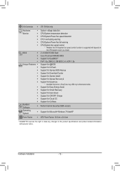
... Dual BIOS LPC Bus iTE IT8720 Floppy COM Port 3 IEEE 1394a PS/2 KB/Mouse Surround Speaker Out Center/Subwoofer Speaker Out Side Speaker Out MIC Line Out Line In S/PDIF In S/PDIF Out 3 PCI PCI CLK (33 MHz) (Note 1) Simultaneous output for DVI-D and HDMI is populated with the PCIEX4 slot. GA-880GA-UD3H...-D (Note 1) PCIe CLK (100 MHz) 2 PCI Express x1 (Note 2) 1 PCI Express x4 (Note 2) PCI Express Bus ATA-133/100/66/33 IDE Channel 2 SATA 3Gb/s GIGABYTE SATA2 PCI Bus T.I.
... Dual BIOS LPC Bus iTE IT8720 Floppy COM Port 3 IEEE 1394a PS/2 KB/Mouse Surround Speaker Out Center/Subwoofer Speaker Out Side Speaker Out MIC Line Out Line In S/PDIF In S/PDIF Out 3 PCI PCI CLK (33 MHz) (Note 1) Simultaneous output for DVI-D and HDMI is populated with the PCIEX4 slot. GA-880GA-UD3H...-D (Note 1) PCIe CLK (100 MHz) 2 PCI Express x1 (Note 2) 1 PCI Express x4 (Note 2) PCI Express Bus ATA-133/100/66/33 IDE Channel 2 SATA 3Gb/s GIGABYTE SATA2 PCI Bus T.I.
Manual
Page 12
...; 2 x 8 Mbit/16 Mbit flash ŠŠ Use of licensed AWARD BIOS ŠŠ Support for DualBIOS™ ŠŠ PnP 1.0a, DMI 2.0, SM BIOS 2.4, ACPI 1.0b Unique Features ŠŠ Support for @BIOS ŠŠ Support for Q-Flash ŠŠ Support for Xpress BIOS Rescue ŠŠ Support for Download Center ŠŠ Support...
...; 2 x 8 Mbit/16 Mbit flash ŠŠ Use of licensed AWARD BIOS ŠŠ Support for DualBIOS™ ŠŠ PnP 1.0a, DMI 2.0, SM BIOS 2.4, ACPI 1.0b Unique Features ŠŠ Support for @BIOS ŠŠ Support for Q-Flash ŠŠ Support for Xpress BIOS Rescue ŠŠ Support for Download Center ŠŠ Support...
Manual
Page 16
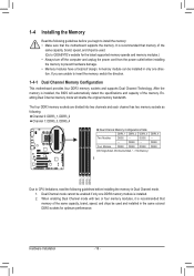
... only one DDR3 memory module is recommended that memory of the same capacity, brand, speed, and chips be used . (Go to GIGABYTE's website for optimum performance. It is installed, the BIOS will double the original memory bandwidth. The four DDR3 memory sockets are unable to CPU limitations, read the following : Channel 0: DDR3_1...
... only one DDR3 memory module is recommended that memory of the same capacity, brand, speed, and chips be used . (Go to GIGABYTE's website for optimum performance. It is installed, the BIOS will double the original memory bandwidth. The four DDR3 memory sockets are unable to CPU limitations, read the following : Channel 0: DDR3_1...

Manual
Page 18
...Locate an expansion slot that came with a screw. 5. Remove the metal slot cover from the power outlet before you begin to make any required BIOS changes for your computer. Align the card with the expansion card in the slot. 3. Make sure the metal contacts on the top edge of ... expansion card to prevent hardware damage. Secure the card's metal bracket to the chassis back panel with your operating system. If necessary, go to BIOS Setup to install an expansion card: • Make sure the motherboard supports the expansion card. Turn on the card until it is fully inserted...
...Locate an expansion slot that came with a screw. 5. Remove the metal slot cover from the power outlet before you begin to make any required BIOS changes for your computer. Align the card with the expansion card in the slot. 3. Make sure the metal contacts on the top edge of ... expansion card to prevent hardware damage. Secure the card's metal bracket to the chassis back panel with your operating system. If necessary, go to BIOS Setup to install an expansion card: • Make sure the motherboard supports the expansion card. Turn on the card until it is fully inserted...

Manual
Page 19
...ATI Catalyst™ Control Center. Configuring the Graphics Driver After installing the motherboard driver in the operating system first. - 19 - BIOS Setup Enter BIOS Setup to Disabled. - Select CrossFire™ on the Graphics menu on the PCIEX16 slot. System Requirements - Step 2: Plug ... First to 256MB or 512MB. (Note 2) - Set UMA Frame Buffer Size to OnChipVGA. A. Read the following items under the Advanced BIOS Features menu: - An ATI Hybrid CrossFireX-supported graphics card (Note 1) B. Windows 7/Vista operating system - Set Surround View to set the...
...ATI Catalyst™ Control Center. Configuring the Graphics Driver After installing the motherboard driver in the operating system first. - 19 - BIOS Setup Enter BIOS Setup to Disabled. - Select CrossFire™ on the Graphics menu on the PCIEX16 slot. System Requirements - Step 2: Plug ... First to 256MB or 512MB. (Note 2) - Set UMA Frame Buffer Size to OnChipVGA. A. Read the following items under the Advanced BIOS Features menu: - An ATI Hybrid CrossFireX-supported graphics card (Note 1) B. Windows 7/Vista operating system - Set Surround View to set the...

Manual
Page 21
...devices such as a USB keyboard/mouse, USB printer, USB flash drive and etc. • When removing the cable connected to Chapter 2, "BIOS Setup," "Ad- vanced BIOS Features," for video output: DVI-D, HDMI and D-Sub. Do not rock it straight out from the motherboard. • When removing the cable...is compatible to the USB 2.0/1.1 specification. The table below . • Memory: Two 1 GB DDR3 1066 memory modules with dual channel mode enabled • BIOS Setup: At least 256 MB of the LAN port LEDs. Dual Display Combination DVI-D + D-Sub DVI-D + HDMI HDMI + D-Sub Supported or Not ...
...devices such as a USB keyboard/mouse, USB printer, USB flash drive and etc. • When removing the cable connected to Chapter 2, "BIOS Setup," "Ad- vanced BIOS Features," for video output: DVI-D, HDMI and D-Sub. Do not rock it straight out from the motherboard. • When removing the cable...is compatible to the USB 2.0/1.1 specification. The table below . • Memory: Two 1 GB DDR3 1066 memory modules with dual channel mode enabled • BIOS Setup: At least 256 MB of the LAN port LEDs. Dual Display Combination DVI-D + D-Sub DVI-D + HDMI HDMI + D-Sub Supported or Not ...

Manual
Page 27
... hard drive. 10) BAT (Battery) The battery provides power to keep the values (such as BIOS configurations, date, and time information) in the CMOS when the computer is turned off your - Hardware Installation The GIGABYTE SATA2 supports RAID 0, RAID 1 and JBOD. Replace the battery when the battery voltage drops to ...a low level, or the CMOS values may not be accurate or may clear the CMOS values by GIGABYTE SATA2) The SATA connectors conform to SATA 3Gb/s standard and are not able to touch the positive and negative terminals of the battery (...
... hard drive. 10) BAT (Battery) The battery provides power to keep the values (such as BIOS configurations, date, and time information) in the CMOS when the computer is turned off your - Hardware Installation The GIGABYTE SATA2 supports RAID 0, RAID 1 and JBOD. Replace the battery when the battery voltage drops to ...a low level, or the CMOS values may not be accurate or may clear the CMOS values by GIGABYTE SATA2) The SATA connectors conform to SATA 3Gb/s standard and are not able to touch the positive and negative terminals of the battery (...

Manual
Page 28
... switch on the chassis that can detect if the chassis cover has been removed. When connecting your system using the power switch (refer to Chapter 2, "BIOS Setup," "Power Management Setup," for information about beep codes. • HD (Hard Drive Activity LED, Blue) Connects to the reset switch on the... system reports system startup status by chassis. The front panel design may issue beeps in S1 sleep state. S1 Blinking tem is detected, the BIOS may differ by issuing a beep code. The LED is off your chassis front panel module to this header according to the speaker on the ...
... switch on the chassis that can detect if the chassis cover has been removed. When connecting your system using the power switch (refer to Chapter 2, "BIOS Setup," "Power Management Setup," for information about beep codes. • HD (Hard Drive Activity LED, Blue) Connects to the reset switch on the... system reports system startup status by chassis. The front panel design may issue beeps in S1 sleep state. S1 Blinking tem is detected, the BIOS may differ by issuing a beep code. The LED is off your chassis front panel module to this header according to the speaker on the ...

Manual
Page 32
.... Open: Normal Short: Clear CMOS Values • Always turn off your computer, be sure to remove the jumper cap from the jumper. date information and BIOS configurations) and reset the CMOS values to clear the CMOS values (e.g. Definition 1 NDCD- 9 1 2 NSIN 10 2 3 NSOUT 4 NDTR- 5 GND 6 NDSR- 7 NRTS- 8 NCTS- 9 NRI- ...CMOS values and before turning on the two pins to temporarily short the two pins or use a metal object like a screwdriver to Chapter 2, "BIOS Setup," for a few seconds. Failure to do so may cause damage to the motherboard. • After system restart, go to...
.... Open: Normal Short: Clear CMOS Values • Always turn off your computer, be sure to remove the jumper cap from the jumper. date information and BIOS configurations) and reset the CMOS values to clear the CMOS values (e.g. Definition 1 NDCD- 9 1 2 NSIN 10 2 3 NSOUT 4 NDTR- 5 GND 6 NDSR- 7 NRTS- 8 NCTS- 9 NRI- ...CMOS values and before turning on the two pins to temporarily short the two pins or use a metal object like a screwdriver to Chapter 2, "BIOS Setup," for a few seconds. Failure to do so may cause damage to the motherboard. • After system restart, go to...

Manual
Page 33
... code during system startup, saving system parameters and loading operating system, etc. To upgrade the BIOS, use either the GIGABYTE Q-Flash or @BIOS utility. • Q-Flash allows the user to prevent system instability or other unexpected results. Chapter 2 BIOS Setup BIOS (Basic Input and Output System) records hardware parameters of the system in the CMOS.
... code during system startup, saving system parameters and loading operating system, etc. To upgrade the BIOS, use either the GIGABYTE Q-Flash or @BIOS utility. • Q-Flash allows the user to prevent system instability or other unexpected results. Chapter 2 BIOS Setup BIOS (Basic Input and Output System) records hardware parameters of the system in the CMOS.

Manual
Page 34
...The system will still be used for one time only. BIOS Setup - 34 - The POST Screen Award Modular BIOS v6.00PG, An Energy Star Ally Copyright (C) 1984-2010, Award Software, Inc. Motherboard Model BIOS Version GA-880GA-UD3H F3b . . . . : BIOS Setup : XpressRecovery2 : Boot Menu : Qflash 06/04.../2010-RS880P-SB850-7A66BG0IC-00 Function Keys Function Keys Function Keys: : POST SCREEN Press the key to show the BIOS POST screen at system startup, refer...
...The system will still be used for one time only. BIOS Setup - 34 - The POST Screen Award Modular BIOS v6.00PG, An Energy Star Ally Copyright (C) 1984-2010, Award Software, Inc. Motherboard Model BIOS Version GA-880GA-UD3H F3b . . . . : BIOS Setup : XpressRecovery2 : Boot Menu : Qflash 06/04.../2010-RS880P-SB850-7A66BG0IC-00 Function Keys Function Keys Function Keys: : POST SCREEN Press the key to show the BIOS POST screen at system startup, refer...

Manual
Page 35
...Save & Exit Setup Exit Without Saving ESC: Quit F8: Q-Flash Select Item F10: Save & Exit Setup Change CPU's Clock & Voltage F11: Save CMOS to BIOS F12: Load CMOS from BIOS BIOS Setup Program Function Keys Move the selection bar to select an item Execute command or enter the submenu Main Menu: Exit the... screen. Submenu Help While in a submenu, press to exit the help screen (General Help) of function keys available for reference only and may differ by BIOS version. - 35 - Help for each item is in the Item Help block on the right side of the submenu. • If you do not ...
...Save & Exit Setup Exit Without Saving ESC: Quit F8: Q-Flash Select Item F10: Save & Exit Setup Change CPU's Clock & Voltage F11: Save CMOS to BIOS F12: Load CMOS from BIOS BIOS Setup Program Function Keys Move the selection bar to select an item Execute command or enter the submenu Main Menu: Exit the... screen. Submenu Help While in a submenu, press to exit the help screen (General Help) of function keys available for reference only and may differ by BIOS version. - 35 - Help for each item is in the Item Help block on the right side of the submenu. • If you do not ...

Manual
Page 36
...61550; MB Intelligent Tweaker(M.I.T.) Use this menu to configure the clock, frequency and voltages of your system becomes unstable and you have loaded the BIOS default settings, you to restrict access to see information about autodetected system/CPU temperature, system voltage and fan speed, etc. Load ... and date, hard drive types, floppy disk drive types, and the type of errors that stop the system boot, etc. Advanced BIOS Features Use this menu to configure the device boot order, advanced features available on the CPU, and the primary display adapter. Integrated...
...61550; MB Intelligent Tweaker(M.I.T.) Use this menu to configure the clock, frequency and voltages of your system becomes unstable and you have loaded the BIOS default settings, you to restrict access to see information about autodetected system/CPU temperature, system voltage and fan speed, etc. Load ... and date, hard drive types, floppy disk drive types, and the type of errors that stop the system boot, etc. Advanced BIOS Features Use this menu to configure the device boot order, advanced features available on the CPU, and the primary display adapter. Integrated...

Manual
Page 37
... not to alter the default settings to prevent system instability or other unexpected results. (Inadequately altering the settings may result in system's failure to boot. BIOS Setup This page is recommended that you made is dependent on your overall system configurations. Incorrectly doing overclock/overvoltage may result in damage to optimize...
... not to alter the default settings to prevent system instability or other unexpected results. (Inadequately altering the settings may result in system's failure to boot. BIOS Setup This page is recommended that you made is dependent on your overall system configurations. Incorrectly doing overclock/overvoltage may result in damage to optimize...

Manual
Page 38
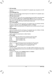
... of the onboard graphics output from the D-SUB/DVI-D or D-SUB/HDMI. This option is configurable only if Init Display First under Advanced BIOS Features is set to manually set the VGA Core clock. (Default: Auto) VGA Core Clock(MHz) Allows you to determine whether to allocate...Options are: Auto (default), 128MB, 256MB, 512MB. MS-DOS, for example, will use only this memory for the onboard graphics controller. Auto BIOS automatically determines the primary display port for the onboard graphics controller. The adjustable range is from 200 MHz to which port the display device is...
... of the onboard graphics output from the D-SUB/DVI-D or D-SUB/HDMI. This option is configurable only if Init Display First under Advanced BIOS Features is set to manually set the VGA Core clock. (Default: Auto) VGA Core Clock(MHz) Allows you to determine whether to allocate...Options are: Auto (default), 128MB, 256MB, 512MB. MS-DOS, for example, will use only this memory for the onboard graphics controller. Auto BIOS automatically determines the primary display port for the onboard graphics controller. The adjustable range is from 200 MHz to which port the display device is...
Manual
Page 39
.... X8.00 Sets Memory Clock to X6.66. CPU Frequency(MHz) Allows you to manually set the CPU host frequency. Auto (default) allows the BIOS to X4.00. Set Memory Clock Determines whether to manually set the frequency for the HT Link between the CPU and chipset. The adjustable range... is from 200 MHz to 500 MHz. BIOS Setup The adjustable range is from 100 MHz to 150 MHz. The adjustable range is dependent on the CPU being used . HT Link Frequency ...
.... X8.00 Sets Memory Clock to X6.66. CPU Frequency(MHz) Allows you to manually set the CPU host frequency. Auto (default) allows the BIOS to X4.00. Set Memory Clock Determines whether to manually set the frequency for the HT Link between the CPU and chipset. The adjustable range... is from 200 MHz to 500 MHz. BIOS Setup The adjustable range is from 100 MHz to 150 MHz. The adjustable range is dependent on the CPU being used . HT Link Frequency ...

Manual
Page 40
BIOS Setup - 40 - Auto -- -- Auto 5T 5T Auto 110ns 110ns Auto -- -- Auto 10T 10T Auto 5T 5T Auto 33T 33T Auto 4T 4T DCT0 DCT1 [Auto] ...
BIOS Setup - 40 - Auto -- -- Auto 5T 5T Auto 110ns 110ns Auto -- -- Auto 10T 10T Auto 5T 5T Auto 33T 33T Auto 4T 4T DCT0 DCT1 [Auto] ...


