Manual
Page 3
...copyright laws and is 1.0. Example: Documentation Classifications In order to assist in this product, GIGABYTE provides the following types of documentations: For quick set-up of GIGABYTE. Check your motherboard looks like this manual are legally registered to the specifications and features ...respective owners. For example, "REV: 1.0" means the revision of this manual may be made by any form or by GIGABYTE without GIGABYTE's prior written permission. Copyright © 2011 GIGA-BYTE TECHNOLOGY CO., LTD. For product-related information, check on our website at:...
...copyright laws and is 1.0. Example: Documentation Classifications In order to assist in this product, GIGABYTE provides the following types of documentations: For quick set-up of GIGABYTE. Check your motherboard looks like this manual are legally registered to the specifications and features ...respective owners. For example, "REV: 1.0" means the revision of this manual may be made by any form or by GIGABYTE without GIGABYTE's prior written permission. Copyright © 2011 GIGA-BYTE TECHNOLOGY CO., LTD. For product-related information, check on our website at:...
Manual
Page 4
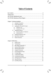
Table of Contents Box Contents...6 Optional Items...6 GA-770T-D3L Motherboard Layout 7 GA-770T-D3L Motherboard Block Diagram 8 Chapter 1 Hardware Installation 9 1-1 Installation Precautions 9 1-2 Product Specifications 10 1-3 Installing the CPU and CPU ... an Expansion Card 18 1-6 Back Panel Connectors 19 1-7 Internal Connectors 21 Chapter 2 BIOS Setup 31 2-1 Startup Screen 32 2-2 The Main Menu 33 2-3 MB Intelligent Tweaker(M.I.T 35 2-4 Standard CMOS Features 40 2-5 Advanced BIOS Features 42 2-6 Integrated Peripherals 44 2-7 Power Management Setup 47 2-8 PC Health Status ...
Table of Contents Box Contents...6 Optional Items...6 GA-770T-D3L Motherboard Layout 7 GA-770T-D3L Motherboard Block Diagram 8 Chapter 1 Hardware Installation 9 1-1 Installation Precautions 9 1-2 Product Specifications 10 1-3 Installing the CPU and CPU ... an Expansion Card 18 1-6 Back Panel Connectors 19 1-7 Internal Connectors 21 Chapter 2 BIOS Setup 31 2-1 Startup Screen 32 2-2 The Main Menu 33 2-3 MB Intelligent Tweaker(M.I.T 35 2-4 Standard CMOS Features 40 2-5 Advanced BIOS Features 42 2-6 Integrated Peripherals 44 2-7 Power Management Setup 47 2-8 PC Health Status ...

Manual
Page 5
... 56 3-4 Contact...57 3-5 System...57 3-6 Download Center 58 3-7 New Utilities...58 Chapter 4 Unique Features 59 4-1 Xpress Recovery2 59 4-2 BIOS Update Utilities 62 4-2-1 Updating the BIOS with the Q-Flash Utility 62 4-2-2 Updating the BIOS with the @BIOS Utility 65 4-3 EasyTune 6...66 4-4 Easy Energy Saver 67 4-5 Q-Share...69 4-6 SMART Recovery 70 4-7 Auto Green...71 Chapter 5 Appendix...
... 56 3-4 Contact...57 3-5 System...57 3-6 Download Center 58 3-7 New Utilities...58 Chapter 4 Unique Features 59 4-1 Xpress Recovery2 59 4-2 BIOS Update Utilities 62 4-2-1 Updating the BIOS with the Q-Flash Utility 62 4-2-2 Updating the BIOS with the @BIOS Utility 65 4-3 EasyTune 6...66 4-4 Easy Energy Saver 67 4-5 Q-Share...69 4-6 SMART Recovery 70 4-7 Auto Green...71 Chapter 5 Appendix...
Manual
Page 8
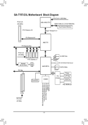
GA-770T-D3L Motherboard Block Diagram CPU CLK+/- (200 MHz) PCIe CLK (100 MHz) AM3+/AM3 CPU DDR3 1666 (O.C.)/1333/1066 MHz Dual Channel Memory 1 PCI Express x16 ... Transport 3.0 PCI Express x16 PCI Express Bus PCIe CLK (100 MHz) x1 x1 x1 x1 4 PCI Express x1 Realtek RTL8111D/E RJ45 LAN PCI Bus Dual BIOS AMD 770 12 USB Ports AMD SB710 ATA-133/100/66/33 IDE Channel 6 SATA 3Gb/s CODEC LPC Bus iTE IT8720 Floppy LPT Port COM...
GA-770T-D3L Motherboard Block Diagram CPU CLK+/- (200 MHz) PCIe CLK (100 MHz) AM3+/AM3 CPU DDR3 1666 (O.C.)/1333/1066 MHz Dual Channel Memory 1 PCI Express x16 ... Transport 3.0 PCI Express x16 PCI Express Bus PCIe CLK (100 MHz) x1 x1 x1 x1 4 PCI Express x1 Realtek RTL8111D/E RJ45 LAN PCI Bus Dual BIOS AMD 770 12 USB Ports AMD SB710 ATA-133/100/66/33 IDE Channel 6 SATA 3Gb/s CODEC LPC Bus iTE IT8720 Floppy LPT Port COM...

Manual
Page 11
... w 1 x parallel port w 1 x serial port w 1 x coaxial S/PDIF Out connector w 8 x USB 2.0/1.1 ports w 1 x RJ-45 port w 3 x audio jacks (Line In/Line Out/Microphone) w iTE IT8720 chip Hardware Monitor w w w w w w BIOS w w w w System voltage detection CPU/System temperature detection CPU/System/Power fan speed detection CPU overheating warning CPU/System/Power fan fail warning CPU/System fan...
... w 1 x parallel port w 1 x serial port w 1 x coaxial S/PDIF Out connector w 8 x USB 2.0/1.1 ports w 1 x RJ-45 port w 3 x audio jacks (Line In/Line Out/Microphone) w iTE IT8720 chip Hardware Monitor w w w w w w BIOS w w w w System voltage detection CPU/System temperature detection CPU/System/Power fan speed detection CPU overheating warning CPU/System/Power fan fail warning CPU/System fan...
Manual
Page 12
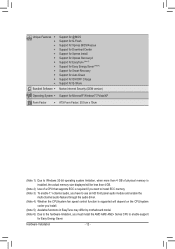
Hardware Installation - 12 - Unique Features w w w w w w w w w w w w Bundled Software w Support for @BIOS Support for Q-Flash Support for Xpress BIOS Rescue Support for Download Center Support for Xpress Install Support for Xpress Recovery2 Support for EasyTune (Note 5) Support for Easy Energy Saver (Note 6) Support for ...
Hardware Installation - 12 - Unique Features w w w w w w w w w w w w Bundled Software w Support for @BIOS Support for Q-Flash Support for Xpress BIOS Rescue Support for Download Center Support for Xpress Install Support for Xpress Recovery2 Support for EasyTune (Note 5) Support for Easy Energy Saver (Note 6) Support for ...
Manual
Page 16
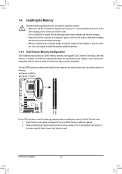
... with two memory modules, it is recommended that memory of the same capacity, brand, speed, and chips be used . (Go to GIGABYTE's website for the latest supported memory speeds and memory modules.) • Always turn off the computer and unplug the power cord from the power... the motherboard supports the memory. Hardware Installation - 16 - A memory module can be enabled if only one DDR3 memory module is installed, the BIOS will double the original memory bandwidth. Dual Channel mode cannot be installed in only one memory socket as following: Channel 0: DDR3_1 Channel 1: DDR3_2...
... with two memory modules, it is recommended that memory of the same capacity, brand, speed, and chips be used . (Go to GIGABYTE's website for the latest supported memory speeds and memory modules.) • Always turn off the computer and unplug the power cord from the power... the motherboard supports the memory. Hardware Installation - 16 - A memory module can be enabled if only one DDR3 memory module is installed, the BIOS will double the original memory bandwidth. Dual Channel mode cannot be installed in only one memory socket as following: Channel 0: DDR3_1 Channel 1: DDR3_2...

Manual
Page 18
... slot. Make sure the metal contacts on the top edge of the card until it is securely seated in your computer. If necessary, go to BIOS Setup to install an expansion card: • Make sure the motherboard supports the expansion card. Carefully read the manual that supports your expansion card. •...; Always turn off the computer and unplug the power cord from the power outlet before you begin to make any required BIOS changes for your expansion card in the slot. 3.
... slot. Make sure the metal contacts on the top edge of the card until it is securely seated in your computer. If necessary, go to BIOS Setup to install an expansion card: • Make sure the motherboard supports the expansion card. Carefully read the manual that supports your expansion card. •...; Always turn off the computer and unplug the power cord from the power outlet before you begin to make any required BIOS changes for your expansion card in the slot. 3.

Manual
Page 25
...• RES (Reset Switch, Green): Connects to the pin assignments below. When connecting your system using the power switch (refer to Chapter 2, "BIOS Setup," "Power Management Setup," for information about beep codes. • HD (Hard Drive Activity LED, Blue) Connects to this header according to ... Switch Speaker MSG+ MSG- RESRES+ CICI+ PWR+ PWR- The system reports system startup status by chassis. If a problem is detected, the BIOS may configure the way to turn off (S5). • PW (Power Switch, Red): Connects to the chassis intrusion switch/sensor on when the...
...• RES (Reset Switch, Green): Connects to the pin assignments below. When connecting your system using the power switch (refer to Chapter 2, "BIOS Setup," "Power Management Setup," for information about beep codes. • HD (Hard Drive Activity LED, Blue) Connects to this header according to ... Switch Speaker MSG+ MSG- RESRES+ CICI+ PWR+ PWR- The system reports system startup status by chassis. If a problem is detected, the BIOS may configure the way to turn off (S5). • PW (Power Switch, Red): Connects to the chassis intrusion switch/sensor on when the...
Manual
Page 28
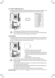
... battery: 1. Danger of the battery holder, making them short for one . 14) F_USB1/F_USB2 (USB Headers) The headers conform to keep the values (such as BIOS configurations, date, and time information) in the power cord and restart your computer. • Always turn off your computer and unplug the power cord from...
... battery: 1. Danger of the battery holder, making them short for one . 14) F_USB1/F_USB2 (USB Headers) The headers conform to keep the values (such as BIOS configurations, date, and time information) in the power cord and restart your computer. • Always turn off your computer and unplug the power cord from...

Manual
Page 29
... and before turning on the two pins to temporarily short the two pins or use a metal object like a screwdriver to touch the two pins for BIOS configurations). - 29 - Failure to do so may cause damage to the motherboard. • After system restart, go to... BIOS Setup to load factory defaults (select Load Optimized Defaults) or manually configure the BIOS settings (refer to clear the CMOS values (e.g. Open: Normal Short: Clear CMOS Values • Always turn off your computer, be...
... and before turning on the two pins to temporarily short the two pins or use a metal object like a screwdriver to touch the two pins for BIOS configurations). - 29 - Failure to do so may cause damage to the motherboard. • After system restart, go to... BIOS Setup to load factory defaults (select Load Optimized Defaults) or manually configure the BIOS settings (refer to clear the CMOS values (e.g. Open: Normal Short: Clear CMOS Values • Always turn off your computer, be...
Manual
Page 31
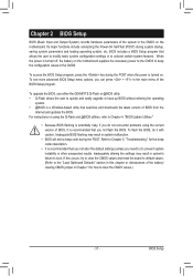
...settings (unless you can press + in the main menu of the BIOS Setup program. Its major functions include conducting the Power-On Self-Test (POST) during the POST. To upgrade the BIOS, use either the GIGABYTE Q-Flash or @BIOS utility. • Q-Flash allows the user to quickly and easily ...upgrade or back up BIOS without entering the operating system. • @BIOS is turned off, the battery on the motherboard. To flash ...
...settings (unless you can press + in the main menu of the BIOS Setup program. Its major functions include conducting the Power-On Self-Test (POST) during the POST. To upgrade the BIOS, use either the GIGABYTE Q-Flash or @BIOS utility. • Q-Flash allows the user to quickly and easily ...upgrade or back up BIOS without entering the operating system. • @BIOS is turned off, the battery on the motherboard. To flash ...
Manual
Page 32
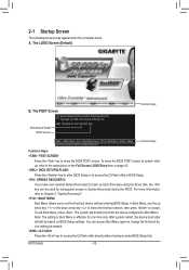
...device configured in Boot Menu. You can be based on page 43. : BIOS SETUP\Q-FLASH Press the key to enter BIOS Setup or to access the Q-Flash utility in Boot Menu is effective for GA-770T-D3L F3a . . . . : BIOS Setup : XpressRecovery2 : Boot Menu : Qflash 06/30/2010-RX780-SB710-...7A66CG08C-00 Function Keys Function Keys: : POST SCREEN Press the key to accept. BIOS Setup - 32 - To exit Boot Menu, press . Note: The setting in BIOS Setup. : XPRESS RECOVERY2 ...
...device configured in Boot Menu. You can be based on page 43. : BIOS SETUP\Q-FLASH Press the key to enter BIOS Setup or to access the Q-Flash utility in Boot Menu is effective for GA-770T-D3L F3a . . . . : BIOS Setup : XpressRecovery2 : Boot Menu : Qflash 06/30/2010-RX780-SB710-...7A66CG08C-00 Function Keys Function Keys: : POST SCREEN Press the key to accept. BIOS Setup - 32 - To exit Boot Menu, press . Note: The setting in BIOS Setup. : XPRESS RECOVERY2 ...
Manual
Page 33
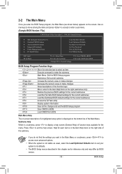
... & Exit Setup Exit Without Saving ESC: Quit F8: Q-Flash Select Item F10: Save & Exit Setup Change CPU's Clock & Voltage F11: Save CMOS to BIOS F12: Load CMOS from BIOS BIOS Setup Program Function Keys Move the selection bar to select an item Execute command or enter the submenu Main Menu: Exit the... option is not stable as shown below) appears on the screen. Submenu Help While in this chapter are for reference only and may differ by BIOS version. - 33 - 2-2 The Main Menu Once you want in the Main Menu or a submenu, press + to access more advanced options. • When the ...
... & Exit Setup Exit Without Saving ESC: Quit F8: Q-Flash Select Item F10: Save & Exit Setup Change CPU's Clock & Voltage F11: Save CMOS to BIOS F12: Load CMOS from BIOS BIOS Setup Program Function Keys Move the selection bar to select an item Execute command or enter the submenu Main Menu: Exit the... option is not stable as shown below) appears on the screen. Submenu Help While in this chapter are for reference only and may differ by BIOS version. - 33 - 2-2 The Main Menu Once you want in the Main Menu or a submenu, press + to access more advanced options. • When the ...

Manual
Page 34
... carry out this task.) Exit Without Saving Abandon all the changes made in effect. First select the profile you to save the current BIOS settings to a profile. Pressing to see information about autodetected system/CPU temperature, system voltage and fan speed, etc. Load Fail-Safe...Change, set , or disable password. The Functions of the and keys (For the Main Menu Only) F11: Save CMOS to BIOS This function allows you wish to load, then press to complete. MB Intelligent Tweaker(M.I.T.) Use this menu to configure the clock, frequency and ...
... carry out this task.) Exit Without Saving Abandon all the changes made in effect. First select the profile you to save the current BIOS settings to a profile. Pressing to see information about autodetected system/CPU temperature, system voltage and fan speed, etc. Load Fail-Safe...Change, set , or disable password. The Functions of the and keys (For the Main Menu Only) F11: Save CMOS to BIOS This function allows you wish to load, then press to complete. MB Intelligent Tweaker(M.I.T.) Use this menu to configure the clock, frequency and ...
Manual
Page 35
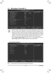
...: Optimized Defaults (Note) This item appears only if you install a CPU that you made is dependent on your overall system configurations. If this feature. - 35 - BIOS Setup 2-3 MB Intelligent Tweaker(M.I.T.) CMOS Setup Utility-Copyright (C) 1984-2010 Award Software MB Intelligent Tweaker(M.I.T.) } Advanced Clock Calibration CPU Clock Ratio CPU NorthBridge Freq. (Note...
...: Optimized Defaults (Note) This item appears only if you install a CPU that you made is dependent on your overall system configurations. If this feature. - 35 - BIOS Setup 2-3 MB Intelligent Tweaker(M.I.T.) CMOS Setup Utility-Copyright (C) 1984-2010 Award Software MB Intelligent Tweaker(M.I.T.) } Advanced Clock Calibration CPU Clock Ratio CPU NorthBridge Freq. (Note...
Manual
Page 36
... (Core 2), Value (Core 3) This option is configurable only when Advanced Clock Calibration is dependent on the CPU being used ). Auto Lets the BIOS to enable all CPU cores. CPU NorthBridge Freq. (Note) Allows you to determine whether to be configurable. Disabled Disables this function. (Default) .... Manual allows the items below to enable Advanced Clock Calibration when using an AMD Black Edition CPU. A message which says "BIOS Is Updating EC Firmware!!! Value (All Cores) This option is configurable only when Advanced Clock Calibration is highly recommended that the ...
... (Core 2), Value (Core 3) This option is configurable only when Advanced Clock Calibration is dependent on the CPU being used ). Auto Lets the BIOS to enable all CPU cores. CPU NorthBridge Freq. (Note) Allows you to determine whether to be configurable. Disabled Disables this function. (Default) .... Manual allows the items below to enable Advanced Clock Calibration when using an AMD Black Edition CPU. A message which says "BIOS Is Updating EC Firmware!!! Value (All Cores) This option is configurable only when Advanced Clock Calibration is highly recommended that the ...

Manual
Page 37
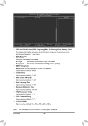
... Time x Minimum RAS Active Time x 1T/2T Command Timing x TwTr Command Delay x Trfc0 for DIMM1 x Trfc2 for the HT Link between the CPU and chipset. BIOS Setup Manual allows the memory clock control item below to be configurable. (Default: Auto) Memory Clock This option is configurable only when Set Memory Clock... manually set the memory clock as required. X8.00 Sets Memory Clock to 200 MHz~2 GHz. The adjustable range is set the memory clock. Auto BIOS will automatically adjust the HT Link Frequency. (Default) 200 MHz~2 GHz Sets HT Link Frequency to X8.00. Auto lets...
... Time x Minimum RAS Active Time x 1T/2T Command Timing x TwTr Command Delay x Trfc0 for DIMM1 x Trfc2 for the HT Link between the CPU and chipset. BIOS Setup Manual allows the memory clock control item below to be configurable. (Default: Auto) Memory Clock This option is configurable only when Set Memory Clock... manually set the memory clock as required. X8.00 Sets Memory Clock to 200 MHz~2 GHz. The adjustable range is set the memory clock. Auto BIOS will automatically adjust the HT Link Frequency. (Default) 200 MHz~2 GHz Sets HT Link Frequency to X8.00. Auto lets...
Manual
Page 38
RAS to CAS R/W Delay Options are : Auto (default), 4T~12T. BIOS Setup - 38 - Unganged Sets memory control mode to two single-channel. (Default) DDR3 Timing Items Manual allows all DDR2 Timing items below to set memory ...
RAS to CAS R/W Delay Options are : Auto (default), 4T~12T. BIOS Setup - 38 - Unganged Sets memory control mode to two single-channel. (Default) DDR3 Timing Items Manual allows all DDR2 Timing items below to set memory ...

Manual
Page 39
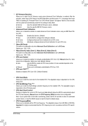
...Displays the normal operating voltage of the CPU. Precharge Time Options are : Auto (default), 5T~12T. RAS to 1.800V. Auto lets the BIOS automatically set the system voltages. NB Voltage Control Allows you install a CPU that supports this feature. - 39 - CPU NB VID Control (...Auto sets the CPU Northbridge VID voltage as required. Trfc2 for DIMM2 Options are: Auto (default), 90ns, 110ns, 160ns, 300ns, 350ns. BIOS Setup Bank Interleaving Enables or disables memory bank interleaving. The adjustable range is dependent on the CPU being installed. (Default: Normal) Note: ...
...Displays the normal operating voltage of the CPU. Precharge Time Options are : Auto (default), 5T~12T. RAS to 1.800V. Auto lets the BIOS automatically set the system voltages. NB Voltage Control Allows you install a CPU that supports this feature. - 39 - CPU NB VID Control (...Auto sets the CPU Northbridge VID voltage as required. Trfc2 for DIMM2 Options are: Auto (default), 90ns, 110ns, 160ns, 300ns, 350ns. BIOS Setup Bank Interleaving Enables or disables memory bank interleaving. The adjustable range is dependent on the CPU being installed. (Default: Normal) Note: ...


