
Manual
Page 1
...Move Enter: Select F5: Previous Values +/-/PU/PD: Value F10: Save F6: Fail-Safe Defaults ESC: Exit F1: General Help F7: Optimized Defaults The BIOS Setup menus described here may differ from the exact settings for storing your motherboard. Installing a conventional SATA hard disk and a solid-state drive (SSD) 2.... Self-Test). If you use an SSD larger than 64 GB, the space beyond 64 GB can still be lost once you have and the BIOS version. - 1 - Installing a conventional SATA hard disk and a solid-state drive (SSD): Besides the conventional SATA disk, you also need an SSD ...
...Move Enter: Select F5: Previous Values +/-/PU/PD: Value F10: Save F6: Fail-Safe Defaults ESC: Exit F1: General Help F7: Optimized Defaults The BIOS Setup menus described here may differ from the exact settings for storing your motherboard. Installing a conventional SATA hard disk and a solid-state drive (SSD) 2.... Self-Test). If you use an SSD larger than 64 GB, the space beyond 64 GB can still be lost once you have and the BIOS version. - 1 - Installing a conventional SATA hard disk and a solid-state drive (SSD): Besides the conventional SATA disk, you also need an SSD ...

Manual
Page 2
..." function of the motherboard driver disk to install the operating system. English 3. Installing the operating system and drivers to the SATA disk: After setting the BIOS, you can begin to install all motherboard drivers, including the Intel Rapid Storage Technology driver. After the installation is 10.5 or above and restarting your...
..." function of the motherboard driver disk to install the operating system. English 3. Installing the operating system and drivers to the SATA disk: After setting the BIOS, you can begin to install all motherboard drivers, including the Intel Rapid Storage Technology driver. After the installation is 10.5 or above and restarting your...
Manual
Page 3
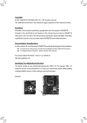
...the use of this product, GIGABYTE provides the following types of...legally registered to assist in this manual may be made by any form or by GIGABYTE without GIGABYTE's prior written permission. Disclaimer Information in this manual may be reproduced, copied, translated...For example, "REV: 1.0" means the revision of the motherboard is the property of GIGABYTE. Documentation Classifications In order to their respective owners. The trademarks mentioned in any means ...://www.gigabyte.com Identifying Your Motherboard Revision The revision number on your motherboard revision before ...
...the use of this product, GIGABYTE provides the following types of...legally registered to assist in this manual may be made by any form or by GIGABYTE without GIGABYTE's prior written permission. Disclaimer Information in this manual may be reproduced, copied, translated...For example, "REV: 1.0" means the revision of the motherboard is the property of GIGABYTE. Documentation Classifications In order to their respective owners. The trademarks mentioned in any means ...://www.gigabyte.com Identifying Your Motherboard Revision The revision number on your motherboard revision before ...
Manual
Page 4
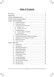
Table of Contents Box Contents...6 Optional Items...6 G1.Sniper 2 Motherboard Layout 7 G1.Sniper 2 Motherboard Block Diagram 8 Chapter 1 Hardware Installation 9 1-1 Installation Precautions 9 1-2 Product Specifications 10 1-3 Installing the CPU and CPU ...Front Access Control Panel 20 1-8 Back Panel Connectors 21 1-9 Internal Connectors 23 Chapter 2 BIOS Setup 35 2-1 Startup Screen 36 2-2 The Main Menu 37 2-3 MB Intelligent Tweaker(M.I.T 39 2-4 Standard CMOS Features 48 2-5 Advanced BIOS Features 50 2-6 Integrated Peripherals 52 2-7 Power Management Setup 54 2-8 PC Health Status ...
Table of Contents Box Contents...6 Optional Items...6 G1.Sniper 2 Motherboard Layout 7 G1.Sniper 2 Motherboard Block Diagram 8 Chapter 1 Hardware Installation 9 1-1 Installation Precautions 9 1-2 Product Specifications 10 1-3 Installing the CPU and CPU ...Front Access Control Panel 20 1-8 Back Panel Connectors 21 1-9 Internal Connectors 23 Chapter 2 BIOS Setup 35 2-1 Startup Screen 36 2-2 The Main Menu 37 2-3 MB Intelligent Tweaker(M.I.T 39 2-4 Standard CMOS Features 48 2-5 Advanced BIOS Features 50 2-6 Integrated Peripherals 52 2-7 Power Management Setup 54 2-8 PC Health Status ...
Manual
Page 5
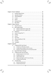
... 62 3-4 Contact...63 3-5 System...63 3-6 Download Center 64 3-7 New Utilities...64 Chapter 4 Unique Features 65 4-1 Xpress Recovery2 65 4-2 BIOS Update Utilities 68 4-2-1 Updating the BIOS with the Q-Flash Utility 68 4-2-2 Updating the BIOS with the @BIOS Utility 71 4-3 EasyTune 6...72 4-4 Dynamic Energy Saver™ 2 73 4-5 Q-Share...75 4-6 Smart 6™ ...76 4-7 Auto Green...80 4-8 eXtreme...
... 62 3-4 Contact...63 3-5 System...63 3-6 Download Center 64 3-7 New Utilities...64 Chapter 4 Unique Features 65 4-1 Xpress Recovery2 65 4-2 BIOS Update Utilities 68 4-2-1 Updating the BIOS with the Q-Flash Utility 68 4-2-2 Updating the BIOS with the @BIOS Utility 71 4-3 EasyTune 6...72 4-4 Dynamic Energy Saver™ 2 73 4-5 Q-Share...75 4-6 Smart 6™ ...76 4-7 Auto Green...80 4-8 eXtreme...
Manual
Page 8
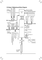
G1.Sniper 2 Motherboard Block Diagram PCIe CLK (100 MHz) 1 PCI Express x16 or 2 PCI Express x8 LGA1155 CPU CPU CLK+/- (100 MHz) DDR3 2133/1866/1600/... PCIe CLK (100 MHz) x1 CREATIVE CA20K2 Intel® Z68 DMI 2.0 FDI 2 USB 3.0/2.0 2 USB 3.0/2.0 Etron EJ168 Etron EJ168 x1 x1 PCI Express Bus HDMI Dual BIOS 4 SATA 3Gb/s 2 SATA 6Gb/s 14 USB 2.0/1.1 x1 PCIe to PCI Bridge LPC Bus iTE IT8728 COM Port PCI Bus PS/2 KB/Mouse Surround Speaker Out...
G1.Sniper 2 Motherboard Block Diagram PCIe CLK (100 MHz) 1 PCI Express x16 or 2 PCI Express x8 LGA1155 CPU CPU CLK+/- (100 MHz) DDR3 2133/1866/1600/... PCIe CLK (100 MHz) x1 CREATIVE CA20K2 Intel® Z68 DMI 2.0 FDI 2 USB 3.0/2.0 2 USB 3.0/2.0 Etron EJ168 Etron EJ168 x1 x1 PCI Express Bus HDMI Dual BIOS 4 SATA 3Gb/s 2 SATA 6Gb/s 14 USB 2.0/1.1 x1 PCIe to PCI Bridge LPC Bus iTE IT8728 COM Port PCI Bus PS/2 KB/Mouse Surround Speaker Out...
Manual
Page 12
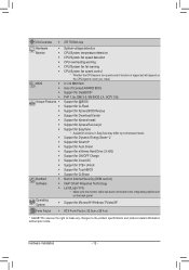
...Mbit flash ŠŠ Use of licensed AWARD BIOS ŠŠ Support for DualBIOS™ ŠŠ PnP 1.0a, DMI 2.0, SM BIOS 2.4, ACPI 1.0b Unique Features ŠŠ Support for @BIOS ŠŠ Support for Q-Flash ŠŠ Support for Xpress BIOS Rescue ŠŠ Support for Download Center ...138;Š Support for Microsoft® Windows 7/Vista/XP Form Factor ŠŠ ATX Form Factor; 30.5cm x 26.4cm * GIGABYTE reserves the right to make any changes to the integrated graphics port on the CPU/system cooler you install. Operating System ŠŠ ...
...Mbit flash ŠŠ Use of licensed AWARD BIOS ŠŠ Support for DualBIOS™ ŠŠ PnP 1.0a, DMI 2.0, SM BIOS 2.4, ACPI 1.0b Unique Features ŠŠ Support for @BIOS ŠŠ Support for Q-Flash ŠŠ Support for Xpress BIOS Rescue ŠŠ Support for Download Center ...138;Š Support for Microsoft® Windows 7/Vista/XP Form Factor ŠŠ ATX Form Factor; 30.5cm x 26.4cm * GIGABYTE reserves the right to make any changes to the integrated graphics port on the CPU/system cooler you install. Operating System ŠŠ ...
Manual
Page 16
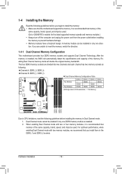
... optimum performance, when enabling Dual Channel mode with two or four memory modules, it is installed, the BIOS will double the original memory bandwidth. Hardware Installation - 16 - A memory module can be used . (Go to GIGABYTE's website for the latest supported memory speeds and memory modules.) •• Always turn off the computer...
... optimum performance, when enabling Dual Channel mode with two or four memory modules, it is installed, the BIOS will double the original memory bandwidth. Hardware Installation - 16 - A memory module can be used . (Go to GIGABYTE's website for the latest supported memory speeds and memory modules.) •• Always turn off the computer...
Manual
Page 18
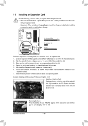
... install your expansion card in your card. PCI Express x16 Slot PCI Express x1 Slot PCI Slot Follow the steps below to make any required BIOS changes for your expansion card(s). 777 Install the driver provided with the slot, and press down on the card are completely inserted into the PCI...
... install your expansion card in your card. PCI Express x16 Slot PCI Express x1 Slot PCI Slot Follow the steps below to make any required BIOS changes for your expansion card(s). 777 Install the driver provided with the slot, and press down on the card are completely inserted into the PCI...
Manual
Page 28
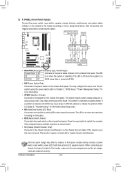
...PW (Power Switch, Red): Connects to the power switch on the chassis front panel. When connecting your system using the power switch (refer to Chapter 2, "BIOS Setup," "Power Management Setup," for information about beep codes. •• HD (Hard Drive Activity LED, Blue) Connects to the hard drive activity LED on... Switch Speaker MSG+ MSG- PW+ PWSPEAK+ SPEAK- 2 20 1 19 HD+ HD- One single short beep will be heard if no problem is detected, the BIOS may issue beeps in S3/S4/S5 Off S3/S4 sleep state or powered off your chassis front panel module to this header according to...
...PW (Power Switch, Red): Connects to the power switch on the chassis front panel. When connecting your system using the power switch (refer to Chapter 2, "BIOS Setup," "Power Management Setup," for information about beep codes. •• HD (Hard Drive Activity LED, Blue) Connects to the hard drive activity LED on... Switch Speaker MSG+ MSG- PW+ PWSPEAK+ SPEAK- 2 20 1 19 HD+ HD- One single short beep will be heard if no problem is detected, the BIOS may issue beeps in S3/S4/S5 Off S3/S4 sleep state or powered off your chassis front panel module to this header according to...
Manual
Page 31
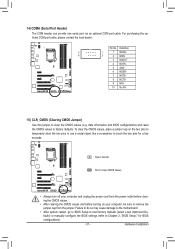
... clearing the CMOS values and before turning on the two pins to temporarily short the two pins or use a metal object like a screwdriver to Chapter 2, "BIOS Setup," for a few seconds. Hardware Installation Definition 9 1 1 NDCD- 10 2 2 NSIN 3 NSOUT 4 NDTR- 5 GND 6 NDSR- 7 NRTS- 8 NCTS- 9 ... •• After system restart, go to BIOS Setup to load factory defaults (select Load Optimized Defaults) or manually configure the BIOS settings (refer to touch the two pins for BIOS configurations). - 31 - date information and BIOS configurations) and reset the CMOS values to clear ...
... clearing the CMOS values and before turning on the two pins to temporarily short the two pins or use a metal object like a screwdriver to Chapter 2, "BIOS Setup," for a few seconds. Hardware Installation Definition 9 1 1 NDCD- 10 2 2 NSIN 3 NSOUT 4 NDTR- 5 GND 6 NDSR- 7 NRTS- 8 NCTS- 9 ... •• After system restart, go to BIOS Setup to load factory defaults (select Load Optimized Defaults) or manually configure the BIOS settings (refer to touch the two pins for BIOS configurations). - 31 - date information and BIOS configurations) and reset the CMOS values to clear ...
Manual
Page 32
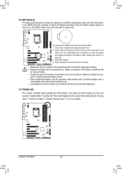
... number of lighted LEDs indicates the CPU loading. You may be lost. 16) BAT (Battery) The battery provides power to keep the values (such as BIOS configurations, date, and time information) in the CMOS when the computer is replaced with an incorrect model. •• Contact the place of purchase or...
... number of lighted LEDs indicates the CPU loading. You may be lost. 16) BAT (Battery) The battery provides power to keep the values (such as BIOS configurations, date, and time information) in the CMOS when the computer is replaced with an incorrect model. •• Contact the place of purchase or...
Manual
Page 33
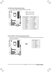
... overclocking (Quick Boost) button's cable from the included 5.25" Front Access Control Panel. 4 6 1 3 Pin No. 1 2 3 4 5 6 Definition Vcc3 B_L1 B_L2 No Pin ICH_GP10 GND - 33 - DB_PORT BIOS Switc 1 1 19 TPM w/housing 20 Pin No. 1 2 3 4 5 6 7 8 9 10 Definition LCLK GND LFRAME No Pin LRESET NC LAD3 LAD2 VCC3 LAD1 1 Voltage measurement module(X58A-OC...
... overclocking (Quick Boost) button's cable from the included 5.25" Front Access Control Panel. 4 6 1 3 Pin No. 1 2 3 4 5 6 Definition Vcc3 B_L1 B_L2 No Pin ICH_GP10 GND - 33 - DB_PORT BIOS Switc 1 1 19 TPM w/housing 20 Pin No. 1 2 3 4 5 6 7 8 9 10 Definition LCLK GND LFRAME No Pin LRESET NC LAD3 LAD2 VCC3 LAD1 1 Voltage measurement module(X58A-OC...
Manual
Page 35
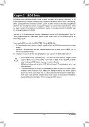
... program that searches and downloads the latest version of the BIOS Setup program. To upgrade the BIOS, use either the GIGABYTE Q-Flash or @BIOS utility. • Q-Flash allows the user to quickly and easily upgrade or back up BIOS without entering the operating system. • @BIOS is turned off, the battery on the motherboard supplies the...
... program that searches and downloads the latest version of the BIOS Setup program. To upgrade the BIOS, use either the GIGABYTE Q-Flash or @BIOS utility. • Q-Flash allows the user to quickly and easily upgrade or back up BIOS without entering the operating system. • @BIOS is turned off, the battery on the motherboard supplies the...
Manual
Page 36
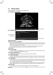
...asks if you want to change the first boot device setting as needed. : Q-FLASH Press the key to access the Q-Flash utility directly without entering BIOS Setup. The system will display a message during the POST. Note: This message will still be used for one time only. Press to enable AHCI ...mode or to set to its default values, the monitor will directly boot from the device configured in time. Motherboard Model BIOS Version G1.Sniper 2 F1c . . . . In Boot Menu, use the up hard drive data using the driver disk, the key can access Boot Menu again to...
...asks if you want to change the first boot device setting as needed. : Q-FLASH Press the key to access the Q-Flash utility directly without entering BIOS Setup. The system will display a message during the POST. Note: This message will still be used for one time only. Press to enable AHCI ...mode or to set to its default values, the monitor will directly boot from the device configured in time. Motherboard Model BIOS Version G1.Sniper 2 F1c . . . . In Boot Menu, use the up hard drive data using the driver disk, the key can access Boot Menu again to...
Manual
Page 37
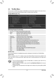
...are for the current submenus Access the Q-Flash utility Display system information Save all the changes and exit the BIOS Setup program Save CMOS to BIOS Load CMOS from BIOS Main Menu Help The on-screen description of a highlighted setup option is displayed on the right side of ... Without Saving ESC: Quit F8: Q-Flash Select Item F10: Save & Exit Setup Change CPU's Clock & Voltage F11: Save CMOS to BIOS F12: Load CMOS from BIOS BIOS Setup Program Function Keys Move the selection bar to select an item Execute command or enter the submenu Main Menu: Exit the...
...are for the current submenus Access the Q-Flash utility Display system information Save all the changes and exit the BIOS Setup program Save CMOS to BIOS Load CMOS from BIOS Main Menu Help The on-screen description of a highlighted setup option is displayed on the right side of ... Without Saving ESC: Quit F8: Q-Flash Select Item F10: Save & Exit Setup Change CPU's Clock & Voltage F11: Save CMOS to BIOS F12: Load CMOS from BIOS BIOS Setup Program Function Keys Move the selection bar to select an item Execute command or enter the submenu Main Menu: Exit the...
Manual
Page 38
...can use the SPACE key) and then press to complete. F12: Load CMOS from a profile created before, without the hassles of reconfiguring the BIOS settings. Pressing to 8 profiles (Profile 1-8) and name each profile. First enter the profile name (to erase the default profile name, use this menu to...to configure the system time and date, hard drive types, and the type of errors that stop the system boot, etc. Advanced BIOS Features Use this menu to configure the device boot order, advanced features available on the CPU, and the primary display adapter. Integrated ...
...can use the SPACE key) and then press to complete. F12: Load CMOS from a profile created before, without the hassles of reconfiguring the BIOS settings. Pressing to 8 profiles (Profile 1-8) and name each profile. First enter the profile name (to erase the default profile name, use this menu to...to configure the system time and date, hard drive types, and the type of errors that stop the system boot, etc. Advanced BIOS Features Use this menu to configure the device boot order, advanced features available on the CPU, and the primary display adapter. Integrated ...
Manual
Page 39
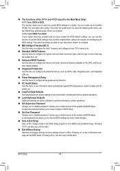
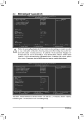
...Miscellaneous Settings [Press Enter] [Press Enter] [Press Enter] [Press Enter] [Press Enter] Item Help Menu Level BIOS Version BCLK CPU Frequency Memory Frequency Total Memory Size CPU Temperature F1c 99.80 MHz 3094.12 MHz 1332.71 MHz 1024 ...(Inadequately altering the settings may result in system's failure to CPU, chipset, or memory and reduce the useful life of these components. BIOS Setup 2-3 MB Intelligent Tweaker(M.I.T.) CMOS Setup Utility-Copyright (C) 1984-2011 Award Software MB Intelligent Tweaker(M.I.T.) } M.I .T Current Status } ...
...Miscellaneous Settings [Press Enter] [Press Enter] [Press Enter] [Press Enter] [Press Enter] Item Help Menu Level BIOS Version BCLK CPU Frequency Memory Frequency Total Memory Size CPU Temperature F1c 99.80 MHz 3094.12 MHz 1332.71 MHz 1024 ...(Inadequately altering the settings may result in system's failure to CPU, chipset, or memory and reduce the useful life of these components. BIOS Setup 2-3 MB Intelligent Tweaker(M.I.T.) CMOS Setup Utility-Copyright (C) 1984-2011 Award Software MB Intelligent Tweaker(M.I.T.) } M.I .T Current Status } ...
Manual
Page 40
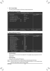
... F10: Save F6: Fail-Safe Defaults ESC: Exit F1: General Help F7: Optimized Defaults CPU Clock Ratio Allows you install a CPU that supports this feature. BIOS Setup - 40 - For more information about Intel CPUs' unique features, please visit Intel's website. Current Status This screen provides information on the CPU being installed...
... F10: Save F6: Fail-Safe Defaults ESC: Exit F1: General Help F7: Optimized Defaults CPU Clock Ratio Allows you install a CPU that supports this feature. BIOS Setup - 40 - For more information about Intel CPUs' unique features, please visit Intel's website. Current Status This screen provides information on the CPU being installed...

Manual
Page 41
...using an Intel CPU that supports this setting. (Default: Auto) Real-Time Ratio Changes in order to reduce the current. Auto lets the BIOS automatically configure this setting. (Default: Auto) Turbo Ratio (1-Core)/(2-Core)/(3-Core)/(4-Core) (Note) Allows you to set a current limit for operating... will be reduced during system halt state to decrease power consumption. This feature only works for CPU Turbo mode. Auto lets the BIOS automatically configure this setting. (Default: Auto) Internal CPU PLL Overvoltage Enabled allows CPU PLL voltage to operate at default value. Disabled...
...using an Intel CPU that supports this setting. (Default: Auto) Real-Time Ratio Changes in order to reduce the current. Auto lets the BIOS automatically configure this setting. (Default: Auto) Turbo Ratio (1-Core)/(2-Core)/(3-Core)/(4-Core) (Note) Allows you to set a current limit for operating... will be reduced during system halt state to decrease power consumption. This feature only works for CPU Turbo mode. Auto lets the BIOS automatically configure this setting. (Default: Auto) Internal CPU PLL Overvoltage Enabled allows CPU PLL voltage to operate at default value. Disabled...


