
Manual/User Guide
Page 13
6.3.3 6.4 6.4.1 6.4.2 6.4.3 6.4.4 6.4.5 Diagnostic test ...6-12 Troubleshooting Procedures 6-13 Outline of troubleshooting procedures 6-13 Troubleshooting with disk drive replacement in the field 6-13 Troubleshooting at the repair site 6-15 Troubleshooting with parts replacement in the factory 6-16 Finding possibly faulty parts 6-16 CHAPTER 7 ERROR ANALYSIS 7-1 7.1 Error Analysis Information Collection 7-1 7.1.1 Sense data...7-1 7.1.2 Sense key, sense code, and subsense...
6.3.3 6.4 6.4.1 6.4.2 6.4.3 6.4.4 6.4.5 Diagnostic test ...6-12 Troubleshooting Procedures 6-13 Outline of troubleshooting procedures 6-13 Troubleshooting with disk drive replacement in the field 6-13 Troubleshooting at the repair site 6-15 Troubleshooting with parts replacement in the factory 6-16 Finding possibly faulty parts 6-16 CHAPTER 7 ERROR ANALYSIS 7-1 7.1 Error Analysis Information Collection 7-1 7.1.1 Sense data...7-1 7.1.2 Sense key, sense code, and subsense...
Manual/User Guide
Page 33
...less). (*4) At power-off state after installation Vibration displacement should be less than 100 mVp-p. 2.1.4 Error rate Errors detected during initialization and replaced by one retry should be 10 or less per 108 seeks. 2.1.5 Reliability (1) Mean Time Between Failures (MTBF) MTBF of the IDD ...during its life time is defined as: MTBF= Operating time (hours) at the drive connector side, during drive ready state. (*6) The terminator power pin (SCSI connector) which cannot be recovered within 63 retries and ECC correction should be distributed...
...less). (*4) At power-off state after installation Vibration displacement should be less than 100 mVp-p. 2.1.4 Error rate Errors detected during initialization and replaced by one retry should be 10 or less per 108 seeks. 2.1.5 Reliability (1) Mean Time Between Failures (MTBF) MTBF of the IDD ...during its life time is defined as: MTBF= Operating time (hours) at the drive connector side, during drive ready state. (*6) The terminator power pin (SCSI connector) which cannot be recovered within 63 retries and ECC correction should be distributed...
Manual/User Guide
Page 34
... trouble, cable failures, or other failures not caused by a well-trained service mechanic to diagnose and repair a drive malfunction. Therefore, the user must design the system cabinet so that requires repair, adjustments, or replacement. The drive is designed for a MTTR of the equipment means failure that the average DE surface temperature is as...
... trouble, cable failures, or other failures not caused by a well-trained service mechanic to diagnose and repair a drive malfunction. Therefore, the user must design the system cabinet so that requires repair, adjustments, or replacement. The drive is designed for a MTTR of the equipment means failure that the average DE surface temperature is as...
Manual/User Guide
Page 76
... recommended). (6) Storage a) Provide vaporproof packaging for storage. c) Indicate "This Side Up" and "Handle With Care" on or until the drive completely stops (for replacing. (4) Packaging a) Store the drive in Subsection 4.2.2 (vertical direction is on hard material such as a desk. For the carrying direction at delivery, use one of the package so that it is...
... recommended). (6) Storage a) Provide vaporproof packaging for storage. c) Indicate "This Side Up" and "Handle With Care" on or until the drive completely stops (for replacing. (4) Packaging a) Store the drive in Subsection 4.2.2 (vertical direction is on hard material such as a desk. For the carrying direction at delivery, use one of the package so that it is...
Manual/User Guide
Page 96
...difficult to access the connector position, the cable may be determined in an antistatic vinyl pack and provide packing (see Section 5.1). 5.8 Spare Disk Drive See 2.1.1, "Model name and order number," to make sure the spindle motor completely stops after power was turned off. MC Model uses a single... cable for replacement or as a spare. 5-22 C141-E166 If it in consideration of the requirements specific to the system. a) Remove the power cable. c) When...
...difficult to access the connector position, the cable may be determined in an antistatic vinyl pack and provide packing (see Section 5.1). 5.8 Spare Disk Drive See 2.1.1, "Model name and order number," to make sure the spindle motor completely stops after power was turned off. MC Model uses a single... cable for replacement or as a spare. 5-22 C141-E166 If it in consideration of the requirements specific to the system. a) Remove the power cable. c) When...

Manual/User Guide
Page 102
...the colored wire connected to pin 1. 6.2.2 Maintenance requirements (1) Preventive maintenance Preventive maintenance such as replacing air filters is not required. Connect the ribbon cable to a cable connector with a wrist strap connected to the disk drive, turn the power off before handling. To prevent electrical damage to ground before connecting or .... Do not remove a PCA. 4. Do not use a conductive cleaner to the device. 2. Opening the disk enclosure may cause the damage to clean a disk drive assembly. 5. Ribbon cables are marked with a colored line. CAUTION 1.
...the colored wire connected to pin 1. 6.2.2 Maintenance requirements (1) Preventive maintenance Preventive maintenance such as replacing air filters is not required. Connect the ribbon cable to a cable connector with a wrist strap connected to the disk drive, turn the power off before handling. To prevent electrical damage to ground before connecting or .... Do not remove a PCA. 4. Do not use a conductive cleaner to the device. 2. Opening the disk enclosure may cause the damage to clean a disk drive assembly. 5. Ribbon cables are marked with a colored line. CAUTION 1.
Manual/User Guide
Page 103
... data is destroyed during servicing or repair. The DE cannot be replaced in the field. C141-E166 6-7 Contact Fujitsu representative to submit information for the disk drive. (3) Parts that can be replaced in the field The PCA cannot be replaced in the field. (4) Service system and repairs Fujitsu has the service system and repair facility for...
... data is destroyed during servicing or repair. The DE cannot be replaced in the field. C141-E166 6-7 Contact Fujitsu representative to submit information for the disk drive. (3) Parts that can be replaced in the field The PCA cannot be replaced in the field. (4) Service system and repairs Fujitsu has the service system and repair facility for...
Manual/User Guide
Page 104
.... (2) Factory maintenance (parts replacement) • This replacement can only be done by Fujitsu. • Replacement includes maintenance training and OEM engineer support. This section explains the two maintenance levels. (1) Field maintenance (disk drive replacement) • This replacement is done at the user's site. • Replacement uses standard tools. • Replacement is faulty, replace the whole disk drive since repair requires special...
.... (2) Factory maintenance (parts replacement) • This replacement can only be done by Fujitsu. • Replacement includes maintenance training and OEM engineer support. This section explains the two maintenance levels. (1) Field maintenance (disk drive replacement) • This replacement is done at the user's site. • Replacement uses standard tools. • Replacement is faulty, replace the whole disk drive since repair requires special...
Manual/User Guide
Page 105
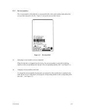
... the corresponding number with ¡ (see Figure 6.2). C141-E166 6-9 Figure 6.1 Revision label (1) Indicating revision number at factory shipment When the disk drive is shipped from the factory, the revision number is indicated by enclosing the corresponding number in the corresponding letter line with = (see Figure 6.2). (2)... Changing revision number in the field To change the revision number because parts are replaced or other modification is applied in the corresponding letter line up to the DE. Figure 6.1 shows the revision label format.
... the corresponding number with ¡ (see Figure 6.2). C141-E166 6-9 Figure 6.1 Revision label (1) Indicating revision number at factory shipment When the disk drive is shipped from the factory, the revision number is indicated by enclosing the corresponding number in the corresponding letter line with = (see Figure 6.2). (2)... Changing revision number in the field To change the revision number because parts are replaced or other modification is applied in the corresponding letter line up to the DE. Figure 6.1 shows the revision label format.
Manual/User Guide
Page 107
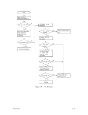
Yes Execute an operation test using a host computer or test equipment No Test results OK? Yes Execute diagnostic test using a host computer or test equipment No Test results OK? Start Start self-test by turning the power on No Test results OK? Yes Normal Analyze disk drive error (Table 6.3) Figure 6.3 Test flowchart C141-E166 6-11 error Yes Replaced or repair disk drive Disk drive No normal? Yes Test using voltage or temperature stress No Test results OK? Yes Continue operation Check host system (Table 6.2) Host system No Analyze system-related normal?
Yes Execute an operation test using a host computer or test equipment No Test results OK? Yes Execute diagnostic test using a host computer or test equipment No Test results OK? Start Start self-test by turning the power on No Test results OK? Yes Normal Analyze disk drive error (Table 6.3) Figure 6.3 Test flowchart C141-E166 6-11 error Yes Replaced or repair disk drive Disk drive No normal? Yes Test using voltage or temperature stress No Test results OK? Yes Continue operation Check host system (Table 6.2) Host system No Analyze system-related normal?
Manual/User Guide
Page 108
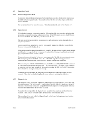
... IDD posts the error to the user. The INIT then posts the error to the INIT. Replace the disk drive to check disk drive performance. The procedures to be caused by replacing the disk drive. 6.3.3 Diagnostic test The diagnostic test is detected by the initial seek operation check routine at power...-on, the LED on the type of the disk drive. To analyze the error posted in the operation test, reconstruct the conditions...
... IDD posts the error to the user. The INIT then posts the error to the INIT. Replace the disk drive to check disk drive performance. The procedures to be caused by replacing the disk drive. 6.3.3 Diagnostic test The diagnostic test is detected by the initial seek operation check routine at power...-on, the LED on the type of the disk drive. To analyze the error posted in the operation test, reconstruct the conditions...
Manual/User Guide
Page 109
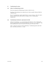
... of a PCA), troubleshooting is straightforward. 6.4.2 Troubleshooting with disk drive replacement in the field, to find faulty part (disk drive or system). Table 6.2 summarizes system-level field troubleshooting. If the newly installed disk drive does not rectify the fault another part of maintenance, we recommend replacing the disk drive as a unit. Troubleshooting must be done in the...
... of a PCA), troubleshooting is straightforward. 6.4.2 Troubleshooting with disk drive replacement in the field, to find faulty part (disk drive or system). Table 6.2 summarizes system-level field troubleshooting. If the newly installed disk drive does not rectify the fault another part of maintenance, we recommend replacing the disk drive as a unit. Troubleshooting must be done in the...
Manual/User Guide
Page 110
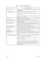
...within 250 mV and +12 VDC is 4.75 to the disk drive and power supply unit. Check the AC voltage from the power supply. If replacing the disk drive does not eliminate the error, the removed disk drive is correctly mounted on all system cables are connected correctly. When ...possible, execute the system level diagnostic routine as explained in the host computer manual. If possible, replace the disk drive. Make sure the maximum ripple peak-to the hardware and software manuals supplied with the system. 6-14 C141-E166 Check that ...
...within 250 mV and +12 VDC is 4.75 to the disk drive and power supply unit. Check the AC voltage from the power supply. If replacing the disk drive does not eliminate the error, the removed disk drive is correctly mounted on all system cables are connected correctly. When ...possible, execute the system level diagnostic routine as explained in the host computer manual. If possible, replace the disk drive. Make sure the maximum ripple peak-to the hardware and software manuals supplied with the system. 6-14 C141-E166 Check that ...
Manual/User Guide
Page 111
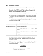
... action Collect sense data, and see Chapter 7. Replace the disk drive, and check that the test method is correct. A media defect list must be changed conditions, the disk drive is incorrect. A media defect list must be included with a disk drive returned to the factory. C141-E166 6-15 If...from the IDD helps with changed to force the error to recreate the error conditions. Replace the disk drive, and check that the test method is correct. To check performance, change the disk drive conditions by sense data, and gives supplementary information on finding the error cause (faulty ...
... action Collect sense data, and see Chapter 7. Replace the disk drive, and check that the test method is correct. A media defect list must be changed conditions, the disk drive is incorrect. A media defect list must be included with a disk drive returned to the factory. C141-E166 6-15 If...from the IDD helps with changed to force the error to recreate the error conditions. Replace the disk drive, and check that the test method is correct. To check performance, change the disk drive conditions by sense data, and gives supplementary information on finding the error cause (faulty ...
Manual/User Guide
Page 112
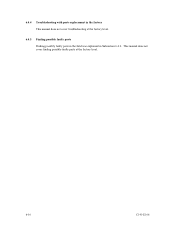
6.4.4 Troubleshooting with parts replacement in Subsection 6.4.2. This manual does not cover finding possibly faulty parts at the factory level. 6.4.5 Finding possibly faulty parts Finding possibly faulty parts in the field was explained in the factory This manual does not cover troubleshooting at the factory level. 6-16 C141-E166
6.4.4 Troubleshooting with parts replacement in Subsection 6.4.2. This manual does not cover finding possibly faulty parts at the factory level. 6.4.5 Finding possibly faulty parts Finding possibly faulty parts in the field was explained in the factory This manual does not cover troubleshooting at the factory level. 6-16 C141-E166
Manual/User Guide
Page 124
...operator panel circuit example ........4-22 external operator panel connector ....... 4-13, 4-14 F factory maintenance (parts replacement) ........6-8 field maintenance (disk drive replacement) ....6-8 finding possibly faulty part 6-16 format capacity 3-9 format of extended sense data 7-2 format parameter ...at factory shipment 6-9 initial seek operation check 6-12 initial self-diagnostic 6-2 installation 5-1 installation requirement 4-1 installation/removal/replacement 5-2 interface (SCSI bus) test 6-5 internal test space 3-4 L large capacity 1-5 leak magnetic flux 4-7 limitation ...
...operator panel circuit example ........4-22 external operator panel connector ....... 4-13, 4-14 F factory maintenance (parts replacement) ........6-8 field maintenance (disk drive replacement) ....6-8 finding possibly faulty part 6-16 format capacity 3-9 format of extended sense data 7-2 format parameter ...at factory shipment 6-9 initial seek operation check 6-12 initial self-diagnostic 6-2 installation 5-1 installation requirement 4-1 installation/removal/replacement 5-2 interface (SCSI bus) test 6-5 internal test space 3-4 L large capacity 1-5 leak magnetic flux 4-7 limitation ...
Manual/User Guide
Page 125
... terminal (on NP model only A-2 setting terminal location 5-5 setting terminator power supply 5-7 spare area in cell 3-5 spare disk drive 5-22 specification 2-1 spindle motor 1-7 standard feature 1-2 START/STOP command 5-12 start/stop of spindle motor 1-5 storage 5-2 surface... track skew and head skew 3-6 troubleshooting at repair site 6-15 troubleshooting procedure 6-13 troubleshooting with disk drive replacement in field 6-13 troubleshooting with part replacement in factory 6-16 U unpackaging 5-2 unrecoverable error rate 2-5 user space 3-3 V verify error recovery parameter ...
... terminal (on NP model only A-2 setting terminal location 5-5 setting terminator power supply 5-7 spare area in cell 3-5 spare disk drive 5-22 specification 2-1 spindle motor 1-7 standard feature 1-2 START/STOP command 5-12 start/stop of spindle motor 1-5 storage 5-2 surface... track skew and head skew 3-6 troubleshooting at repair site 6-15 troubleshooting procedure 6-13 troubleshooting with disk drive replacement in field 6-13 troubleshooting with part replacement in factory 6-16 U unpackaging 5-2 unrecoverable error rate 2-5 user space 3-3 V verify error recovery parameter ...

