
Manual/User Guide
Page 5
... in computer systems. The MANUAL ORGANIZATION section describes organization and scope of fixed disk drives and their use the other manuals. PREFACE This manual describes the MAP3147NC/NP, MAP3735NC/NP and MAP3367NC/NP (hereafter, MAP series), 3.5 type fixed disk drives with an embedded SCSI controller. The need arises, use in details how collect...
... in computer systems. The MANUAL ORGANIZATION section describes organization and scope of fixed disk drives and their use the other manuals. PREFACE This manual describes the MAP3147NC/NP, MAP3735NC/NP and MAP3367NC/NP (hereafter, MAP series), 3.5 type fixed disk drives with an embedded SCSI controller. The need arises, use in details how collect...
Manual/User Guide
Page 6
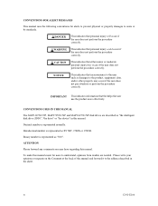
NOTICE This indicates that inconvenience to the user such as "the intelligent disk drive (IDD)", "the drive" or "the device" in this manual and forward it to the address described in the sheet. IMPORTANT This indicates information that ...injury could occur if the user does not perform the procedure correctly. CONVENTIONS USED IN THIS MANUAL The MAP3147NC/NP, MAP3735NC/NP and MAP3367NC/NP disk drives are needed. Hexadecimal number is represented normally. CONVENTIONS FOR ALERT MESSAGES This manual uses the following conventions for users to understand, opinions...
NOTICE This indicates that inconvenience to the user such as "the intelligent disk drive (IDD)", "the drive" or "the device" in this manual and forward it to the address described in the sheet. IMPORTANT This indicates information that ...injury could occur if the user does not perform the procedure correctly. CONVENTIONS USED IN THIS MANUAL The MAP3147NC/NP, MAP3735NC/NP and MAP3367NC/NP disk drives are needed. Hexadecimal number is represented normally. CONVENTIONS FOR ALERT MESSAGES This manual uses the following conventions for users to understand, opinions...
Manual/User Guide
Page 7
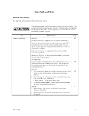
... keeps allowable error byte number, correction is on . • Write protect: CN2 9-10 (NP model only) 3. Hot temperature To prevent injury, do not handle the drive until after the device has 5-1 cooled sufficiently after turning off the power. To short the setting terminal, use the short plug attached when the device...
... keeps allowable error byte number, correction is on . • Write protect: CN2 9-10 (NP model only) 3. Hot temperature To prevent injury, do not handle the drive until after the device has 5-1 cooled sufficiently after turning off the power. To short the setting terminal, use the short plug attached when the device...
Manual/User Guide
Page 8
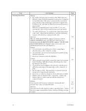
...before connecting or 6-5 disconnecting a cable, connector, or plug. 2. Opening the disk 6-6 enclosure may cause the damage to the disk drive, turn off before requesting repair. Be careful of the insertion orientation of the cable. ESD (Electrostatics Discharge) may cause an irreparable fault.... power is supplied via the SCSI cable, if the power is destroyed during disk drive operation. 3. Fujitsu 6-7 does not assume responsibility if data is turned on the disk drive before connecting or disconnecting a cable, connector, or plug. 3. The RECEIVE DIAGNOSTIC ...
...before connecting or 6-5 disconnecting a cable, connector, or plug. 2. Opening the disk 6-6 enclosure may cause the damage to the disk drive, turn off before requesting repair. Be careful of the insertion orientation of the cable. ESD (Electrostatics Discharge) may cause an irreparable fault.... power is supplied via the SCSI cable, if the power is destroyed during disk drive operation. 3. Fujitsu 6-7 does not assume responsibility if data is turned on the disk drive before connecting or disconnecting a cable, connector, or plug. 3. The RECEIVE DIAGNOSTIC ...
Manual/User Guide
Page 12
...only 5-6 5.3.2 Each mode setting (NP model only 5-7 5.3.3 Mode settings ...5-9 5.4 Mounting Drives...5-10 5.4.1 Check before mounting ...5-10 5.4.2 Mounting procedures...5-10 5.5 Connecting Cables...5-11 5.6 Confirming ...use 5-12 5.6.1 Confirming initial operations 5-12 5.6.2 Checking SCSI connection 5-13 5.6.3 Formatting ...5-16 5.6.4 Setting parameters ...5-18 5.7 Dismounting Drives...5-22 5.8 Spare Disk Drive ...5-22 CHAPTER 6 DIAGNOSTICS AND MAINTENANCE 6-1 6.1 Diagnostics ...6-1 6.1.1 Self-diagnostics ...6-1 6.1.2 Test programs...6-4 6.2 Maintenance Information 6-5 6.2.1 Precautions...
...only 5-6 5.3.2 Each mode setting (NP model only 5-7 5.3.3 Mode settings ...5-9 5.4 Mounting Drives...5-10 5.4.1 Check before mounting ...5-10 5.4.2 Mounting procedures...5-10 5.5 Connecting Cables...5-11 5.6 Confirming ...use 5-12 5.6.1 Confirming initial operations 5-12 5.6.2 Checking SCSI connection 5-13 5.6.3 Formatting ...5-16 5.6.4 Setting parameters ...5-18 5.7 Dismounting Drives...5-22 5.8 Spare Disk Drive ...5-22 CHAPTER 6 DIAGNOSTICS AND MAINTENANCE 6-1 6.1 Diagnostics ...6-1 6.1.1 Self-diagnostics ...6-1 6.1.2 Test programs...6-4 6.2 Maintenance Information 6-5 6.2.1 Precautions...
Manual/User Guide
Page 13
6.3.3 6.4 6.4.1 6.4.2 6.4.3 6.4.4 6.4.5 Diagnostic test ...6-12 Troubleshooting Procedures 6-13 Outline of troubleshooting procedures 6-13 Troubleshooting with disk drive replacement in the field 6-13 Troubleshooting at the repair site 6-15 Troubleshooting with parts replacement in the factory 6-16 Finding possibly faulty parts 6-16 CHAPTER 7 ...
6.3.3 6.4 6.4.1 6.4.2 6.4.3 6.4.4 6.4.5 Diagnostic test ...6-12 Troubleshooting Procedures 6-13 Outline of troubleshooting procedures 6-13 Troubleshooting with disk drive replacement in the field 6-13 Troubleshooting at the repair site 6-15 Troubleshooting with parts replacement in the factory 6-16 Finding possibly faulty parts 6-16 CHAPTER 7 ...
Manual/User Guide
Page 15
FIGURES Figure 1.1 Figure 1.2 Figure 1.3 Figure 1.4 page NC model drives outer view 1-6 NP model drives outer view 1-6 Disk/head configuration...1-7 System configuration ...1-9 Figure 3.1 Figure 3.2 Figure 3.3 Figure 3.4 Figure 3.5 Figure 3.6 Figure 3.7 Figure 3.8 Cylinder configuration...3-2 Spare area in cell ...3-5 Alternate cylinder ...3-5 Track format ...3-6 ...
FIGURES Figure 1.1 Figure 1.2 Figure 1.3 Figure 1.4 page NC model drives outer view 1-6 NP model drives outer view 1-6 Disk/head configuration...1-7 System configuration ...1-9 Figure 3.1 Figure 3.2 Figure 3.3 Figure 3.4 Figure 3.5 Figure 3.6 Figure 3.7 Figure 3.8 Cylinder configuration...3-2 Spare area in cell ...3-5 Alternate cylinder ...3-5 Track format ...3-6 ...
Manual/User Guide
Page 17
... check list (NP model only 5-10 Table 6.1 Self-diagnostic functions ...6-1 Table 6.2 System-level field troubleshooting 6-14 Table 6.3 Disk drive troubleshooting ...6-15 Table 7.1 Definition of sense data ...7-3 Table A.1 CN2 setting terminal (on NP model drives only A-2 Table B.1 SCSI connector (68 pin type LVD 16-bit SCSI): CN1 B-2 Table B.2 SCSI connector (SCA2 type LVD...
... check list (NP model only 5-10 Table 6.1 Self-diagnostic functions ...6-1 Table 6.2 System-level field troubleshooting 6-14 Table 6.3 Disk drive troubleshooting ...6-15 Table 7.1 Definition of sense data ...7-3 Table A.1 CN2 setting terminal (on NP model drives only A-2 Table B.1 SCSI connector (68 pin type LVD 16-bit SCSI): CN1 B-2 Table B.2 SCSI connector (SCA2 type LVD...
Manual/User Guide
Page 19
The MAP series disk drives support the Small Computer System Interface (SCSI) as the powerful command set of the IDD, allow the user to construct a high-performance reliable disk subsystem ... be changed from the format at factory shipment by reinitializing with an embedded SCSI controller. The flexibility and expandability of the MAP series intelligent disk drives (IDD). C141-E166 1-1 Refer to SCSI Logical Interface Specifications for details. CHAPTER 1 GENERAL DESCRIPTION 1.1 Standard Features 1.2 Hardware Structure 1.3 System Configuration This chapter describes the feature...
The MAP series disk drives support the Small Computer System Interface (SCSI) as the powerful command set of the IDD, allow the user to construct a high-performance reliable disk subsystem ... be changed from the format at factory shipment by reinitializing with an embedded SCSI controller. The flexibility and expandability of the MAP series intelligent disk drives (IDD). C141-E166 1-1 Refer to SCSI Logical Interface Specifications for details. CHAPTER 1 GENERAL DESCRIPTION 1.1 Standard Features 1.2 Hardware Structure 1.3 System Configuration This chapter describes the feature...
Manual/User Guide
Page 20
... have the wide transfer function suitable for SCSI-2. 8-bit data bus is available only with the large capacity buffer in the standard 3.5 type fixed disk drive form factor, the IDD is 320 MB/s maximum at the synchronous mode. • 16-bit SCSI: The data transfer rate on the same SCSI bus... is varied as follows. • 8-bit SCSI: 8 drives max. (option for details of the disk drive. For the ultra SCSI model, number of connectable SCSI devices on the SCSI bus is extremely compact. The IDD can manipulate data...
... have the wide transfer function suitable for SCSI-2. 8-bit data bus is available only with the large capacity buffer in the standard 3.5 type fixed disk drive form factor, the IDD is 320 MB/s maximum at the synchronous mode. • 16-bit SCSI: The data transfer rate on the same SCSI bus... is varied as follows. • 8-bit SCSI: 8 drives max. (option for details of the disk drive. For the ultra SCSI model, number of connectable SCSI devices on the SCSI bus is extremely compact. The IDD can manipulate data...
Manual/User Guide
Page 21
To ensure it, you turn off the drive's power. The initiator can queue maximum 128 commands, and optimizes the issuing order of queued commands by the reordering function. The continuous processing up to [... that the command is surely terminated with utilizing high data transfer capability of the SCSI bus regardless of actual data transfer rate of the disk drive. (7) Cache feature After executing the READ command, the IDD reads automatically and stores (prefetches) the subsequent data blocks into the data buffer (Read-ahead caching...
To ensure it, you turn off the drive's power. The initiator can queue maximum 128 commands, and optimizes the issuing order of queued commands by the reordering function. The continuous processing up to [... that the command is surely terminated with utilizing high data transfer capability of the SCSI bus regardless of actual data transfer rate of the disk drive. (7) Cache feature After executing the READ command, the IDD reads automatically and stores (prefetches) the subsequent data blocks into the data buffer (Read-ahead caching...
Manual/User Guide
Page 22
... is programmable, and can be specified at formatting. CAUTION Error rate increase 1. The recoverable Error of the drive might increase when the format would be modified from the complicated error recover processing by these error recovery functions of 512 to 528 bytes. The ... sequence by using the reserve and release functions. (10) Error recovery The IDD can try to recover from errors in SCSI bus or the disk drive using its powerful retry processing. (9) Reserve and release functions The IDD can be transferred to the initiator after being corrected in the data buffer.
... is programmable, and can be specified at formatting. CAUTION Error rate increase 1. The recoverable Error of the drive might increase when the format would be modified from the complicated error recover processing by these error recovery functions of 512 to 528 bytes. The ... sequence by using the reserve and release functions. (10) Error recovery The IDD can try to recover from errors in SCSI bus or the disk drive using its powerful retry processing. (9) Reserve and release functions The IDD can be transferred to the initiator after being corrected in the data buffer.
Manual/User Guide
Page 23
...function enhancing. This makes it ideal for MAP series. The disk subsystem with large capacity can be obtained from 3.5 type disk drives by dividing all cylinders into several partitions and changing the recording density on each partition (constant density recording). (15) Large capacity... capacity can start and stop the spindle motor. (17) Diagnosis The IDD has a diagnostic capability which checks internal controller functions and drive operations to facilitate testing and repair. (18) Low power consumption By using highly integrated LSI components, the power consumption of the IDD...
...function enhancing. This makes it ideal for MAP series. The disk subsystem with large capacity can be obtained from 3.5 type disk drives by dividing all cylinders into several partitions and changing the recording density on each partition (constant density recording). (15) Large capacity... capacity can start and stop the spindle motor. (17) Diagnosis The IDD has a diagnostic capability which checks internal controller functions and drive operations to facilitate testing and repair. (18) Low power consumption By using highly integrated LSI components, the power consumption of the IDD...
Manual/User Guide
Page 24
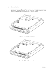
Figure 1.1 NC model drives outer view Figure 1.2 NP model drives outer view 1-6 C141-E166 The IDD is given in Figures 1.1 and 1.2. 1.2 Hardware Structure An outer view of the IDD is composed of the disk, head, spindle motor, mounted disk enclosure (DE) with actuator and air circulation filter, as well as read/write pre-amp with the printed circuit assembly (PCA) of the controller.
Figure 1.1 NC model drives outer view Figure 1.2 NP model drives outer view 1-6 C141-E166 The IDD is given in Figures 1.1 and 1.2. 1.2 Hardware Structure An outer view of the IDD is composed of the disk, head, spindle motor, mounted disk enclosure (DE) with actuator and air circulation filter, as well as read/write pre-amp with the printed circuit assembly (PCA) of the controller.
Manual/User Guide
Page 25
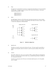
... generates little heat. C141-E166 1-7 Figure 1.3 shows the configuration of disks and heads Base Cover MAP3147NC/NP 0 1 2 3 4 5 6 7 MAP3735NC/NP 0 1 2 3 MAP3367NC/NP 0 1 Figure 1.3 Disk/head configuration (3) Spindle motor The disks are not rotating, and automatically float when the rotation is controlled and positioned via feedback of...disks are positioned on the CCS zone over the disks when the power is off or the spindle motor is controlled by a direct-drive hall-less DC motor. The motor speed is stopped. (1) Disks The disks have an outer diameter of 84 mm (3.3 inch) and...
... generates little heat. C141-E166 1-7 Figure 1.3 shows the configuration of disks and heads Base Cover MAP3147NC/NP 0 1 2 3 4 5 6 7 MAP3735NC/NP 0 1 2 3 MAP3367NC/NP 0 1 Figure 1.3 Disk/head configuration (3) Spindle motor The disks are not rotating, and automatically float when the rotation is controlled and positioned via feedback of...disks are positioned on the CCS zone over the disks when the power is off or the spindle motor is controlled by a direct-drive hall-less DC motor. The motor speed is stopped. (1) Disks The disks have an outer diameter of 84 mm (3.3 inch) and...
Manual/User Guide
Page 28
... combination. For input/output operation, a peripheral device attached to the SCSI bus that operates as target is a single logical unit, the selectable number of disk drive is addressed in Figure 1.4). (1) SCSI bus configuration Up to eight SCSI devices operating as an initiator or a target can be connected to the SCSI bus...
... combination. For input/output operation, a peripheral device attached to the SCSI bus that operates as target is a single logical unit, the selectable number of disk drive is addressed in Figure 1.4). (1) SCSI bus configuration Up to eight SCSI devices operating as an initiator or a target can be connected to the SCSI bus...
Manual/User Guide
Page 30
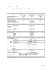
... max (*6) Cable length: 1.5 m max (*7) LVD U160 Cable length: 25 m max (*8) Cable length: 12 m max (*9) Data transfer rate (*10) Disk drive SCSI Synchronous mode 64.1 to 528 byte (Fixed length) SCSI command specification SPI-4 (T10/1365D Rev.7), SAM-2 (T10/1157D Rev.20), SPC-2 (T10/1236D Rev... (60 s max.) 30 s typ. 32/34 MEEPRML 25.4 mm 101.6 mm 146.0 mm 0.75 kg 9.6 W Cable length: 6 m max MAP3367NC/NP 36.74 GB 1 2 48,104 Single- Table 2.2 Function specifications Item Formatted capacity/device (*1) Number of disks Number of heads Number of cylinders (*2) Formatted capacity/track ...
... max (*6) Cable length: 1.5 m max (*7) LVD U160 Cable length: 25 m max (*8) Cable length: 12 m max (*9) Data transfer rate (*10) Disk drive SCSI Synchronous mode 64.1 to 528 byte (Fixed length) SCSI command specification SPI-4 (T10/1365D Rev.7), SAM-2 (T10/1157D Rev.20), SPC-2 (T10/1236D Rev... (60 s max.) 30 s typ. 32/34 MEEPRML 25.4 mm 101.6 mm 146.0 mm 0.75 kg 9.6 W Cable length: 6 m max MAP3367NC/NP 36.74 GB 1 2 48,104 Single- Table 2.2 Function specifications Item Formatted capacity/device (*1) Number of disks Number of heads Number of cylinders (*2) Formatted capacity/track ...
Manual/User Guide
Page 32
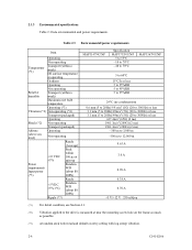
...+5 VDC ±5% (*6) Random W/R (about 80 IOPS) Ripple (*7) MAP3147NC/NP Specification MAP3735NC/NP 5 to 55°C -10 to 70°C -40 to 70°C MAP3367NC/NP 5 to 60°C 15°C/h or less 5 to 95%RH 5 to 95%RH 5 to 95%RH 29°C (no condensation) 0.6 mm (5 to 20Hz)/9.8... m to 3,000 m -300 m to 12,000 m 0.63 A 3.0 A 0.90 A 0.38 A 0.70 A +5 V/+12 V 250 mVp-p (*1) For detail condition, see Section 4.1. (*2) Vibration applied to the drive is measured at near the mounting screw hole on the frame as much as possible. (*3) At random seek write/read and default on retry setting...
...+5 VDC ±5% (*6) Random W/R (about 80 IOPS) Ripple (*7) MAP3147NC/NP Specification MAP3735NC/NP 5 to 55°C -10 to 70°C -40 to 70°C MAP3367NC/NP 5 to 60°C 15°C/h or less 5 to 95%RH 5 to 95%RH 5 to 95%RH 29°C (no condensation) 0.6 mm (5 to 20Hz)/9.8... m to 3,000 m -300 m to 12,000 m 0.63 A 3.0 A 0.90 A 0.38 A 0.70 A +5 V/+12 V 250 mVp-p (*1) For detail condition, see Section 4.1. (*2) Vibration applied to the drive is measured at near the mounting screw hole on the frame as much as possible. (*3) At random seek write/read and default on retry setting...
Manual/User Guide
Page 33
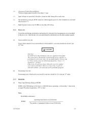
...replaced by one retry should not exceed 1 per 108 seeks. 2.1.5 Reliability (1) Mean Time Between Failures (MTBF) MTBF of the IDD during drive ready state. (*6) The terminator power pin (SCSI connector) which supplies power to other terminators is performed. However, if error byte exceeds its... bits. The sector-data is divided into 6 interleaving sectors, and ECC is defined as: MTBF= Operating time (hours) at the drive connector side, during its allowable number, correction may not be performed properly. (2) Positioning error rate Positioning errors which cannot be recovered within...
...replaced by one retry should not exceed 1 per 108 seeks. 2.1.5 Reliability (1) Mean Time Between Failures (MTBF) MTBF of the IDD during drive ready state. (*6) The terminator power pin (SCSI connector) which supplies power to other terminators is performed. However, if error byte exceeds its... bits. The sector-data is divided into 6 interleaving sectors, and ECC is defined as: MTBF= Operating time (hours) at the drive connector side, during its allowable number, correction may not be performed properly. (2) Positioning error rate Positioning errors which cannot be recovered within...
Manual/User Guide
Page 34
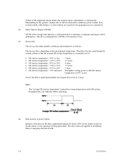
... are not considered. (2) Mean Time To Repair (MTTR) MTTR is operating. (4) Data security at power failure Integrity of the data on the environment temperature. The drive is designed for a MTTR of 30 minutes or less. (3) Service life The service life under suitable conditions and treatment is as low. • DE surface... follows. Therefore, the user must design the system cabinet so that DE surface temperature is 5 years. The above does not applied to diagnose and repair a drive malfunction.
... are not considered. (2) Mean Time To Repair (MTTR) MTTR is operating. (4) Data security at power failure Integrity of the data on the environment temperature. The drive is designed for a MTTR of 30 minutes or less. (3) Service life The service life under suitable conditions and treatment is as low. • DE surface... follows. Therefore, the user must design the system cabinet so that DE surface temperature is 5 years. The above does not applied to diagnose and repair a drive malfunction.


