Manual/User Guide
Page 6
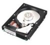
.../MP, MAJ3182MC/MP, MAJ3091MC/MP (hereafter, MAJ series), 3.5 type fixed disk drives with an embedded SCSI controller. This manual is written for users who have a basic understanding of the above disk drive, and gives the requirements and procedures for installing MAH series and MAJ series disk... drives. Chapter 4 INSTALLATION REQUIREMENTS This chapter describes the basic physical and ...
.../MP, MAJ3182MC/MP, MAJ3091MC/MP (hereafter, MAJ series), 3.5 type fixed disk drives with an embedded SCSI controller. This manual is written for users who have a basic understanding of the above disk drive, and gives the requirements and procedures for installing MAH series and MAJ series disk... drives. Chapter 4 INSTALLATION REQUIREMENTS This chapter describes the basic physical and ...
Manual/User Guide
Page 7
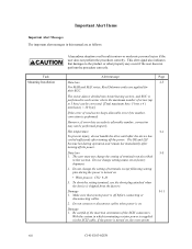
...attention or perform the procedure correctly. CAUTION CAUTION indicates that describes the electrical requirements of model names and product numbers, and SCSI interface functions. Indicates vi C141-E103-02EN APPENDIX A to users or by standards. CONVENTIONS This manual uses the following ...setting terminals and connectors, a list of setting items, the signal assignments of interface connectors, lists of the SCSI interface between host system and disk drive, the data formatted at the factory and device type. DANGER DANGER indicates that inconvenience to the user such ...
...attention or perform the procedure correctly. CAUTION CAUTION indicates that describes the electrical requirements of model names and product numbers, and SCSI interface functions. Indicates vi C141-E103-02EN APPENDIX A to users or by standards. CONVENTIONS This manual uses the following ...setting terminals and connectors, a list of setting items, the signal assignments of interface connectors, lists of the SCSI interface between host system and disk drive, the data formatted at the factory and device type. DANGER DANGER indicates that inconvenience to the user such ...
Manual/User Guide
Page 8
...Fujitsu is . However, in this manual, the typical model names (Note 2) are used unless otherwise noted. This manual indicates; Note 1: Model names M AJ 3 364 MC Interface types MC: LVD, 16-bit SCSI SCA2 connector 160MHz transfer MP: LVD, 16-bit SCSI 68 pin connector 160MHz transfer Formatted capacity (100 MB units) Disk drive... MAH3091 MAH3091MC, MAH3091MP MAJ3364 MAJ3364MC, MAJ3364MP MAJ3182 MAJ3182MC, MAJ3182MP MAJ3091 MAJ3091MC, MAJ3091MP C141-E103-02EN vii These disk drives may be called intelligent disk drives (IDD), drives, or devices in this manual. ...
...Fujitsu is . However, in this manual, the typical model names (Note 2) are used unless otherwise noted. This manual indicates; Note 1: Model names M AJ 3 364 MC Interface types MC: LVD, 16-bit SCSI SCA2 connector 160MHz transfer MP: LVD, 16-bit SCSI 68 pin connector 160MHz transfer Formatted capacity (100 MB units) Disk drive... MAH3091 MAH3091MC, MAH3091MP MAJ3364 MAJ3364MC, MAJ3364MP MAJ3182 MAJ3182MC, MAJ3182MP MAJ3091 MAJ3091MC, MAJ3091MP C141-E103-02EN vii These disk drives may be called intelligent disk drives (IDD), drives, or devices in this manual. ...
Manual/User Guide
Page 9
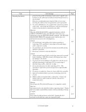
... sure that damages to 5 byte) can be performed properly. With the system in which terminating resistor power is supplied via the SCSI cable, if the power is off the power. This alert signal also indicates that system power is turned on . Important Alert Items... Important Alert Messages The important alert messages in this section. Hot temperature 5-1 To prevent injury, do not handle the drive until after the device has cooled sufficiently after turning off before connecting or disconnecting cables. 2. Alert message Page Data loss 2-5 For MAH...
... sure that damages to 5 byte) can be performed properly. With the system in which terminating resistor power is supplied via the SCSI cable, if the power is off the power. This alert signal also indicates that system power is turned on . Important Alert Items... Important Alert Messages The important alert messages in this section. Hot temperature 5-1 To prevent injury, do not handle the drive until after the device has cooled sufficiently after turning off before connecting or disconnecting cables. 2. Alert message Page Data loss 2-5 For MAH...
Manual/User Guide
Page 10
... collect the error information using the REQUEST SENSE command. Opening the disk enclosure in the self-diagnostics. Check that the SCSI device with the colored wire connected to prevent overheating of the cable. Caution 1. To prevent electrical damage to prevent unexpected... plug. 3. Connect the ribbon cable to a cable connector with the terminating resistor is completely sealed. Fujitsu does not assume responsibility if data is required to the disk drive, turn off before connecting or disconnecting a cable, connector, or plug. 2. Task Mounting Installation Alert ...
... collect the error information using the REQUEST SENSE command. Opening the disk enclosure in the self-diagnostics. Check that the SCSI device with the colored wire connected to prevent overheating of the cable. Caution 1. To prevent electrical damage to prevent unexpected... plug. 3. Connect the ribbon cable to a cable connector with the terminating resistor is completely sealed. Fujitsu does not assume responsibility if data is required to the disk drive, turn off before connecting or disconnecting a cable, connector, or plug. 2. Task Mounting Installation Alert ...
Manual/User Guide
Page 13
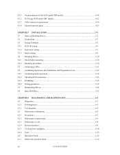
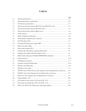
... procedures...5-10 5.5 Connecting Cables...5-11 5.6 Confirming Operations after Installation and Preparation for use 5-12 5.6.1 Confirming initial operations 5-12 5.6.2 Checking SCSI connection...5-13 5.6.3 Formatting ...5-16 5.6.4 Setting parameters ...5-18 5.7 Dismounting Drives...5-22 5.8 Spare Disk Drive ...5-22 CHAPTER 6 DIAGNOSTICS AND MAINTENANCE 6-1 6.1 Diagnostics ...6-1 6.1.1 Self-diagnostics ...6-1 6.1.2 Test programs...6-4 6.2 Maintenance Information ...6-5 6.2.1 Precautions ...6-5 6.2.2 Maintenance requirements...6-6 6.2.3 Maintenance levels ...6-8 6.2.4 Revision numbers...
... procedures...5-10 5.5 Connecting Cables...5-11 5.6 Confirming Operations after Installation and Preparation for use 5-12 5.6.1 Confirming initial operations 5-12 5.6.2 Checking SCSI connection...5-13 5.6.3 Formatting ...5-16 5.6.4 Setting parameters ...5-18 5.7 Dismounting Drives...5-22 5.8 Spare Disk Drive ...5-22 CHAPTER 6 DIAGNOSTICS AND MAINTENANCE 6-1 6.1 Diagnostics ...6-1 6.1.1 Self-diagnostics ...6-1 6.1.2 Test programs...6-4 6.2 Maintenance Information ...6-5 6.2.1 Precautions ...6-5 6.2.2 Maintenance requirements...6-6 6.2.3 Maintenance levels ...6-8 6.2.4 Revision numbers...
Manual/User Guide
Page 14
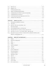
...Diagnostic test ...6-12 Troubleshooting Procedures 6-13 Outline of troubleshooting procedures 6-13 Troubleshooting with disk drive replacement in the field 6-13 Troubleshooting at the repair site 6-15 Troubleshooting with parts ...Sense data (5-2x-xx), (5-3D-00), (5-90-00), (B-47-xx), (B-49-00), (B-4D-xx) and (B-4E-00): SCSI interface error 7-4 CHAPTER 8 PRINCIPLE OF OPERATION 8-1 8.1 Outline...8-1 8.2 Disk Drive Configuration ...8-1 8.2.1 Disks...8-2 8.2.2 Heads...8-2 8.2.3 Spindle mechanism...8-2 8.2.4 Actuator...8-2 8.2.5 Air filters ...8-2 8.3 Circuit Configuration...8-3 8.4 Power-On...
...Diagnostic test ...6-12 Troubleshooting Procedures 6-13 Outline of troubleshooting procedures 6-13 Troubleshooting with disk drive replacement in the field 6-13 Troubleshooting at the repair site 6-15 Troubleshooting with parts ...Sense data (5-2x-xx), (5-3D-00), (5-90-00), (B-47-xx), (B-49-00), (B-4D-xx) and (B-4E-00): SCSI interface error 7-4 CHAPTER 8 PRINCIPLE OF OPERATION 8-1 8.1 Outline...8-1 8.2 Disk Drive Configuration ...8-1 8.2.1 Disks...8-2 8.2.2 Heads...8-2 8.2.3 Spindle mechanism...8-2 8.2.4 Actuator...8-2 8.2.5 Air filters ...8-2 8.3 Circuit Configuration...8-3 8.4 Power-On...
Manual/User Guide
Page 18
... mode setting...5-8 5.4 Write protect setting (CN2 5-8 5.5 Setting of the SCSI interface operation mode (CN2 5-9 5.6 Setting the bus width of the SCSI interface (CN2 5-9 5.7 Default mode settings (by CHANGE DEFINITION command 5-9 5.8 Setting check list ...5-10 6.1 Self-diagnostic functions ...6-1 6.2 System-level field troubleshooting 6-14 6.3 Disk drive troubleshooting ...6-15 7.1 Definition of sense data ...7-3 8.1 MAJ3364 series, MAJ3182...
... mode setting...5-8 5.4 Write protect setting (CN2 5-8 5.5 Setting of the SCSI interface operation mode (CN2 5-9 5.6 Setting the bus width of the SCSI interface (CN2 5-9 5.7 Default mode settings (by CHANGE DEFINITION command 5-9 5.8 Setting check list ...5-10 6.1 Self-diagnostic functions ...6-1 6.2 System-level field troubleshooting 6-14 6.3 Disk drive troubleshooting ...6-15 7.1 Definition of sense data ...7-3 8.1 MAJ3364 series, MAJ3182...
Manual/User Guide
Page 20
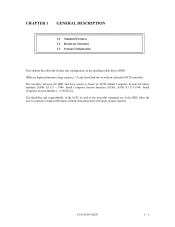
... of the IDD, allow the user to construct a high-performance reliable disk subsystem with an embedded SCSI controller. The interface between the IDD and host system is based on SCSI (Small Computer System Interface) standard [ANSI X3.131 - 1986: Small Computer System Interface... (SCSI), ANSI X3.131-1994: Small Computer System Interface - 2 (SCSI-2)]. C141-E103-02EN 1 - 1 The flexibility and expandability of the SCSI, as well as the powerful command set of the intelligent disk drives (IDD). IDDs are high performance large capacity 3.5...
... of the IDD, allow the user to construct a high-performance reliable disk subsystem with an embedded SCSI controller. The interface between the IDD and host system is based on SCSI (Small Computer System Interface) standard [ANSI X3.131 - 1986: Small Computer System Interface... (SCSI), ANSI X3.131-1994: Small Computer System Interface - 2 (SCSI-2)]. C141-E103-02EN 1 - 1 The flexibility and expandability of the SCSI, as well as the powerful command set of the intelligent disk drives (IDD). IDDs are high performance large capacity 3.5...
Manual/User Guide
Page 21
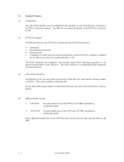
...High speed data transfer • 8-bit SCSI: The data transfer rate on the SCSI bus is 40 MB/s maximum in synchronous mode. • 16-bit SCSI: The data transfer rate on the SCSI bus is 160 MB/s maximum in the standard 3.5 type fixed disk drive form factor, the IDD is extremely compact.... Such a high data transfer rate on the same SCSI bus is varied as 8-bit data bus. For the ultra SCSI model, number of the SCSI CCS (Common Command Set for SCSI-2. 1.1 Standard Features (1) Compactness Since the SCSI controller circuit is ...
...High speed data transfer • 8-bit SCSI: The data transfer rate on the SCSI bus is 40 MB/s maximum in synchronous mode. • 16-bit SCSI: The data transfer rate on the SCSI bus is 160 MB/s maximum in the standard 3.5 type fixed disk drive form factor, the IDD is extremely compact.... Such a high data transfer rate on the same SCSI bus is varied as 8-bit data bus. For the ultra SCSI model, number of the SCSI CCS (Common Command Set for SCSI-2. 1.1 Standard Features (1) Compactness Since the SCSI controller circuit is ...

Manual/User Guide
Page 22
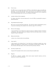
...requests the prefetched data blocks. (8) Command queuing feature The IDD can queue maximum 128 commands, and optimizes the issuing order of the disk drive. (7) Read-ahead cache feature After executing the READ command, the IDD reads automatically and stores (prefetches) the subsequent data blocks into ... the disconnect/reconnect timing on several tracks or cylinder. (6) Programmable multi-segment data buffer The data buffer is transferred between SCSI bus and disk media through this data buffer. Since the initiator can perform the effective input/output operations with utilizing high data...
...requests the prefetched data blocks. (8) Command queuing feature The IDD can queue maximum 128 commands, and optimizes the issuing order of the disk drive. (7) Read-ahead cache feature After executing the READ command, the IDD reads automatically and stores (prefetches) the subsequent data blocks into ... the disconnect/reconnect timing on several tracks or cylinder. (6) Programmable multi-segment data buffer The data buffer is transferred between SCSI bus and disk media through this data buffer. Since the initiator can perform the effective input/output operations with utilizing high data...
Manual/User Guide
Page 23
...the IDD can automatically reassign its powerful retry processing. (10) Error recovery The IDD can try to recover from errors in SCSI bus or the disk drive using its alternate data block. (12) Programmable data block length Data can be accessed in fixed-block length units. The data... block length is released from 3.5 type disk drives by slipping the defective data block at initializing with large capacity can be reallocated in a physical sequence by dividing all cylinders into several ...
...the IDD can automatically reassign its powerful retry processing. (10) Error recovery The IDD can try to recover from errors in SCSI bus or the disk drive using its alternate data block. (12) Programmable data block length Data can be accessed in fixed-block length units. The data... block length is released from 3.5 type disk drives by slipping the defective data block at initializing with large capacity can be reallocated in a physical sequence by dividing all cylinders into several ...

Manual/User Guide
Page 29
...for each logical unit. The initiator selects one SCSI device by specifying that SCSI ID, then specifies the LUN to the SCSI bus that the whole volume of disk drive is a single logical unit, the selectable number of peripheral device Each SCSI device on the bus has its own unique ...address (SCSI ID:#n in unit called as follows: • SCSI ID: • LUN: 8-bit SCSI:Selectable from 0 to 7 (switch selectable) 16-bit SCSI:Selectable from 0 to ...
...for each logical unit. The initiator selects one SCSI device by specifying that SCSI ID, then specifies the LUN to the SCSI bus that the whole volume of disk drive is a single logical unit, the selectable number of peripheral device Each SCSI device on the bus has its own unique ...address (SCSI ID:#n in unit called as follows: • SCSI ID: • LUN: 8-bit SCSI:Selectable from 0 to 7 (switch selectable) 16-bit SCSI:Selectable from 0 to ...

Manual/User Guide
Page 31
...(rpm) Average latency time Seek time (*3) (Read/Write) Minimum Average Maximum Specification MAJ3364 series MAJ3182 series MAJ3091 series 36.4 GB 18.2 GB 9.1 GB 46.6 GB 23.3 GB 11.7 GB 5 3 2 10 5 3 14,792 14,808 13,261 188,928 to 293,888 172,032 to 293,...AVE) External dimensions Height Width Depth Weight Power consumption (*5) Interface Fast SCSI (Single-Ended) Fast 20 SCSI (Single-Ended) Fast 80 SCSI (LVD) Data transfer rate (*10) Disk drive SCSI Synchronous mode Logical data block length (*1) SCSI command specification Data buffer 12.5 W 30 s typ. (60 s ...
...(rpm) Average latency time Seek time (*3) (Read/Write) Minimum Average Maximum Specification MAJ3364 series MAJ3182 series MAJ3091 series 36.4 GB 18.2 GB 9.1 GB 46.6 GB 23.3 GB 11.7 GB 5 3 2 10 5 3 14,792 14,808 13,261 188,928 to 293,888 172,032 to 293,...AVE) External dimensions Height Width Depth Weight Power consumption (*5) Interface Fast SCSI (Single-Ended) Fast 20 SCSI (Single-Ended) Fast 80 SCSI (LVD) Data transfer rate (*10) Disk drive SCSI Synchronous mode Logical data block length (*1) SCSI command specification Data buffer 12.5 W 30 s typ. (60 s ...

Manual/User Guide
Page 33
...(*6) Ready 0.75A 0.7 A Random W/R (about 80 IOPS) 0.9 A 0.8 A Ripple (*7) +5 V/+12 V 250 mVp-p (*1) For detail condition, see Section 4.1. (*2) Vibration applied to the drive is measured at near the mounting screw hole on the frame as much as possible. (*3) At random seek write/read and default on retry setting... Vibration displacement should be less than 2.5 mm. (*5) Input voltages are specified at the connector. (*6) The terminator power pin (SCSI connector) which supplies power to other terminators is not used (See Section 4.3). (*7) High frequency noise is less than 100 mVp...
...(*6) Ready 0.75A 0.7 A Random W/R (about 80 IOPS) 0.9 A 0.8 A Ripple (*7) +5 V/+12 V 250 mVp-p (*1) For detail condition, see Section 4.1. (*2) Vibration applied to the drive is measured at near the mounting screw hole on the frame as much as possible. (*3) At random seek write/read and default on retry setting... Vibration displacement should be less than 2.5 mm. (*5) Input voltages are specified at the connector. (*6) The terminator power pin (SCSI connector) which supplies power to other terminators is not used (See Section 4.3). (*7) High frequency noise is less than 100 mVp...

Manual/User Guide
Page 72
... of the IDD. IMPORTANT 1. For details of the disk drive. This signal is temporarily driven at the GND level when the micro program reads the SCSI ID immediately after the power supply to the IDD has been...actuate the external LED as same as LED on the front panel of command, refer to set up the SCSI ID by short circuiting CN1-A7 and CN1-A8.) C141-E103-02EN 4 - 19 The external LED is...-A12 is connected to the GND, or the CN2-9 and CN2-10 are short-circuited.) A signal for driving the LED is output. 74LS06 or equivalent 150 Ω (IDD) NC1-A2 IMPORTANT This signal is temporarily ...
... of the IDD. IMPORTANT 1. For details of the disk drive. This signal is temporarily driven at the GND level when the micro program reads the SCSI ID immediately after the power supply to the IDD has been...actuate the external LED as same as LED on the front panel of command, refer to set up the SCSI ID by short circuiting CN1-A7 and CN1-A8.) C141-E103-02EN 4 - 19 The external LED is...-A12 is connected to the GND, or the CN2-9 and CN2-10 are short-circuited.) A signal for driving the LED is output. 74LS06 or equivalent 150 Ω (IDD) NC1-A2 IMPORTANT This signal is temporarily ...

Manual/User Guide
Page 88
... follows: 7 > 6 > 5 > 4 > 3 > 2 > 1 > 0 > 15 > 14 > 13 > 12 > 11 > 10 > 9 > 8 5.3.2 Each mode setting (1) Setting terminal power supply Refer to Table 5.2 for controlling the supply of SCSI terminating resistor power from the drive to Figures 5.2 and 5.3. For information on *1 Setting at factory shipment 1-2 Open Short Open Short Open Short Open Short Open Short Open Short Open...
... follows: 7 > 6 > 5 > 4 > 3 > 2 > 1 > 0 > 15 > 14 > 13 > 12 > 11 > 10 > 9 > 8 5.3.2 Each mode setting (1) Setting terminal power supply Refer to Table 5.2 for controlling the supply of SCSI terminating resistor power from the drive to Figures 5.2 and 5.3. For information on *1 Setting at factory shipment 1-2 Open Short Open Short Open Short Open Short Open Short Open Short Open...
Manual/User Guide
Page 91
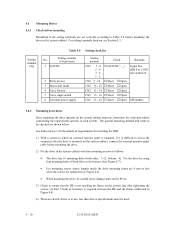
... to be checked are tightened (see Section 5.3. At least 2.5mm of both sides: 3 ×2, bottom: 4). Setting contents (Check item) 1 SCSI ID 2 Write protect 3 Motor start mode 4 Force Narrow 5 Force single ended 6 Terminal power supply Setting position Check CN2 7 - 8 …...- 24 … Short … Open Remarks Upper bus (DB 8 to 15 PI) not connected MP models 5.4.2 Mounting procedures Since mounting the drive depends on the system cabinet structure, determine the work procedures considering the requirements specific to ensure that the DE is in the system cabinet. Fix...
... to be checked are tightened (see Section 5.3. At least 2.5mm of both sides: 3 ×2, bottom: 4). Setting contents (Check item) 1 SCSI ID 2 Write protect 3 Motor start mode 4 Force Narrow 5 Force single ended 6 Terminal power supply Setting position Check CN2 7 - 8 …...- 24 … Short … Open Remarks Upper bus (DB 8 to 15 PI) not connected MP models 5.4.2 Mounting procedures Since mounting the drive depends on the system cabinet structure, determine the work procedures considering the requirements specific to ensure that the DE is in the system cabinet. Fix...

Manual/User Guide
Page 93
... blinks periodically. c) When the IDD status is turned on, the LED blinks an instant and the IDD executes initial selfdiagnosis. d) The disk drive enters the READY status in Subsection 5.6.2. b) Check that motor starts with the IDD power connection position). e) The LED blinks during command execution.... (3) Check items at powering-on a) When power is idle, the LED remains off (when the initiator accesses the IDD via the SCSI bus, the LED lights). (2) Initial operation in this time, the IDD reads "system information" from the system space on . 5.6 Confirming ...
... blinks periodically. c) When the IDD status is turned on, the LED blinks an instant and the IDD executes initial selfdiagnosis. d) The disk drive enters the READY status in Subsection 5.6.2. b) Check that motor starts with the IDD power connection position). e) The LED blinks during command execution.... (3) Check items at powering-on a) When power is idle, the LED remains off (when the initiator accesses the IDD via the SCSI bus, the LED lights). (2) Initial operation in this time, the IDD reads "system information" from the system space on . 5.6 Confirming ...

Manual/User Guide
Page 94
...is connected to e) in initial self-diagnosis the LED blinks. Figure 5.5 shows for the mode that the IDD is connected correctly to the SCSI bus and the initial operation after power is turned on ended normally. In these recommended checking procedures, following items are checked. Note: Following ...The command issue period of the TEST UNIT READY command shall be more than 20 ms. b) To control starting of the controller and disk drive. d) If an error is only an instant. In this section describes the general procedures. (1) Checking procedure Issuing the commands and determining the ...
...is connected to e) in initial self-diagnosis the LED blinks. Figure 5.5 shows for the mode that the IDD is connected correctly to the SCSI bus and the initial operation after power is turned on ended normally. In these recommended checking procedures, following items are checked. Note: Following ...The command issue period of the TEST UNIT READY command shall be more than 20 ms. b) To control starting of the controller and disk drive. d) If an error is only an instant. In this section describes the general procedures. (1) Checking procedure Issuing the commands and determining the ...


