Manual/User Guide
Page 6
... the basics of this manual. This chapter also describes diagnostic methods for installing MAH series and MAJ series disk drives. PREFACE This manual describes the MAH3182MC/MP, MAH3091MC/MP (hereafter, MAH series) and MAJ3364MC/MP, MAJ3182MC/MP, MAJ3091MC/MP (hereafter, MAJ series), 3.5 type fixed disk drives with an embedded SCSI controller. The need arises, use in details how collect the information for setting device number and operation modes, mounting the disk drive, connecting the cables, and confirming drive operation.
... the basics of this manual. This chapter also describes diagnostic methods for installing MAH series and MAJ series disk drives. PREFACE This manual describes the MAH3182MC/MP, MAH3091MC/MP (hereafter, MAH series) and MAJ3364MC/MP, MAJ3182MC/MP, MAJ3091MC/MP (hereafter, MAJ series), 3.5 type fixed disk drives with an embedded SCSI controller. The need arises, use in details how collect the information for setting device number and operation modes, mounting the disk drive, connecting the cables, and confirming drive operation.
Manual/User Guide
Page 8
...-bit SCSI SCA2 connector 160MHz transfer MP: LVD, 16-bit SCSI 68 pin connector 160MHz transfer Formatted capacity (100 MB units) Disk drive size 3: 3.5 type. The suffix of the model name of the disk drive varies depending on the electrical requirements, capacity, and data format at factory shipment of the SCSI, i.e., the interface for drive failures caused by misuse by the user, poor environmental conditions, power trouble, host problems, cable failures, or any failure not caused by the drive itself. Hand Disk Drive Type AH: Number...
...-bit SCSI SCA2 connector 160MHz transfer MP: LVD, 16-bit SCSI 68 pin connector 160MHz transfer Formatted capacity (100 MB units) Disk drive size 3: 3.5 type. The suffix of the model name of the disk drive varies depending on the electrical requirements, capacity, and data format at factory shipment of the SCSI, i.e., the interface for drive failures caused by misuse by the user, poor environmental conditions, power trouble, host problems, cable failures, or any failure not caused by the drive itself. Hand Disk Drive Type AH: Number...
Manual/User Guide
Page 9
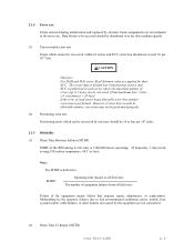
... maximum number of the SCSI connectors. Important Alert Items Important Alert Messages The important alert messages in this section. Do not change the setting of read sector keeps allowable error byte number, correction is turned on . • Write protect: CN2 9-10 3. Make sure that damages to 5 byte) can be performed properly. This alert signal also indicates that system power is performed in this manual are...
... maximum number of the SCSI connectors. Important Alert Items Important Alert Messages The important alert messages in this section. Do not change the setting of read sector keeps allowable error byte number, correction is turned on . • Write protect: CN2 9-10 3. Make sure that damages to 5 byte) can be performed properly. This alert signal also indicates that system power is performed in this manual are...
Manual/User Guide
Page 13
... 68 pin connector 16-bit SCSI model (MP model 4-14 SCA2 type SCSI model (MC model 4-22 Cable connector requirements 4-26 External operator panel ...4-27 CHAPTER 5 INSTALLATION 5-1 5.1 Notes on Handling Drives ...5-1 5.2 Connections...5-3 5.3 Setting Terminals ...5-5 5.3.1 SCSI ID setting...5-6 5.3.2 Each mode setting ...5-7 5.3.3 Mode settings ...5-9 5.4 Mounting Drives...5-10 5.4.1 Check before mounting ...5-10 5.4.2 Mounting procedures...5-10 5.5 Connecting Cables...5-11 5.6 Confirming Operations after Installation and Preparation for use 5-12 5.6.1 Confirming initial operations 5-12...
... 68 pin connector 16-bit SCSI model (MP model 4-14 SCA2 type SCSI model (MC model 4-22 Cable connector requirements 4-26 External operator panel ...4-27 CHAPTER 5 INSTALLATION 5-1 5.1 Notes on Handling Drives ...5-1 5.2 Connections...5-3 5.3 Setting Terminals ...5-5 5.3.1 SCSI ID setting...5-6 5.3.2 Each mode setting ...5-7 5.3.3 Mode settings ...5-9 5.4 Mounting Drives...5-10 5.4.1 Check before mounting ...5-10 5.4.2 Mounting procedures...5-10 5.5 Connecting Cables...5-11 5.6 Confirming Operations after Installation and Preparation for use 5-12 5.6.1 Confirming initial operations 5-12...
Manual/User Guide
Page 18
...capacity (MAH series 3-4 3.4 Format capacity ...3-10 4.1 Surface temperature check point 4-8 4.2 Recommended components for connection 4-26 5.1 SCSI ID setting (CN2) ...5-7 5.2 Setting SCSI terminal power supply (MP 5-7 5.3 Motor start mode setting...5-8 5.4 Write protect setting (CN2 5-8 5.5 Setting of the SCSI interface operation mode (CN2 5-9 5.6 Setting the bus width of the SCSI interface (CN2 5-9 5.7 Default mode settings (by CHANGE DEFINITION command 5-9 5.8 Setting check list ...5-10 6.1 Self-diagnostic functions ...6-1 6.2 System-level field troubleshooting 6-14 6.3 Disk drive...
...capacity (MAH series 3-4 3.4 Format capacity ...3-10 4.1 Surface temperature check point 4-8 4.2 Recommended components for connection 4-26 5.1 SCSI ID setting (CN2) ...5-7 5.2 Setting SCSI terminal power supply (MP 5-7 5.3 Motor start mode setting...5-8 5.4 Write protect setting (CN2 5-8 5.5 Setting of the SCSI interface operation mode (CN2 5-9 5.6 Setting the bus width of the SCSI interface (CN2 5-9 5.7 Default mode settings (by CHANGE DEFINITION command 5-9 5.8 Setting check list ...5-10 6.1 Self-diagnostic functions ...6-1 6.2 System-level field troubleshooting 6-14 6.3 Disk drive...

Manual/User Guide
Page 31
...±0.5% 4.167 msec 0.6 ms (Read)/0.8 ms (Write) 6.7 ms (Read)/7.3 ms (Write) 14.0 ms (Read)/15.0 ms (Write) Start/stop time Start time (*4) Stop time Recording mode Recording density (max) Track density (AVE) External dimensions Height Width Depth Weight Power consumption (*5) Interface Fast SCSI (Single-Ended) Fast 20 SCSI (Single-Ended) Fast 80 SCSI (LVD) Data transfer rate (*10) Disk drive SCSI Synchronous mode Logical data block length (*1) SCSI command specification Data buffer 12.5 W 30 s typ. (60 s max.) 30 s typ. 32/34...
...±0.5% 4.167 msec 0.6 ms (Read)/0.8 ms (Write) 6.7 ms (Read)/7.3 ms (Write) 14.0 ms (Read)/15.0 ms (Write) Start/stop time Start time (*4) Stop time Recording mode Recording density (max) Track density (AVE) External dimensions Height Width Depth Weight Power consumption (*5) Interface Fast SCSI (Single-Ended) Fast 20 SCSI (Single-Ended) Fast 80 SCSI (LVD) Data transfer rate (*10) Disk drive SCSI Synchronous mode Logical data block length (*1) SCSI command specification Data buffer 12.5 W 30 s typ. (60 s max.) 30 s typ. 32/34...

Manual/User Guide
Page 32
... 8000 10000 Seek Difference [512 Cyl/div] MAJ series (*4) The start time is the time from power on 1 connection case. (*9) 1 host, 15 devices case. (*10) The maximum data transfer rate may be changed by transmission characteristics. (*11) The terminator power pin (SCSI connector) which supplies power to the response speed of initiator and by changing the logical block length and using spare sector space. (*1) The formatted capacity can use cable length of up to 3.0 m. (*7) 5 to 8 SCSI devices having capacitance...
... 8000 10000 Seek Difference [512 Cyl/div] MAJ series (*4) The start time is the time from power on 1 connection case. (*9) 1 host, 15 devices case. (*10) The maximum data transfer rate may be changed by transmission characteristics. (*11) The terminator power pin (SCSI connector) which supplies power to the response speed of initiator and by changing the logical block length and using spare sector space. (*1) The formatted capacity can use cable length of up to 3.0 m. (*7) 5 to 8 SCSI devices having capacitance...

Manual/User Guide
Page 33
... the drive is measured at near the mounting screw hole on the frame as much as possible. (*3) At random seek write/read and default on retry setting with log sweep vibration. (*4) At power-off state after installation Vibration displacement should be less than 2.5 mm. (*5) Input voltages are specified at the connector. (*6) The terminator power pin (SCSI connector) which supplies power to other terminators is not used (See...
... the drive is measured at near the mounting screw hole on the frame as much as possible. (*3) At random seek write/read and default on retry setting with log sweep vibration. (*4) At power-off state after installation Vibration displacement should be less than 2.5 mm. (*5) Input voltages are specified at the connector. (*6) The terminator power pin (SCSI connector) which supplies power to other terminators is not used (See...
Manual/User Guide
Page 34
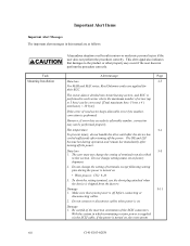
... the error of the equipment means failure that requires repair, adjustments, or replacement. CAUTION Data loss For MAH and MAJ series, Reed Solomon codes are not included in each sector where the maximum number of errors (up to bad environmental conditions, power trouble, host system trouble, cable failures, or other failures not caused by alternate block assignments are applied for their ECC. Mishandling by the operator, failures due...
... the error of the equipment means failure that requires repair, adjustments, or replacement. CAUTION Data loss For MAH and MAJ series, Reed Solomon codes are not included in each sector where the maximum number of errors (up to bad environmental conditions, power trouble, host system trouble, cable failures, or other failures not caused by alternate block assignments are applied for their ECC. Mishandling by the operator, failures due...

Manual/User Guide
Page 71
(5) External operator panel connector Signals a. 16-bit SCSI -ID3, -ID2, -ID1, -ID0: Input signals (CN1-A1, A3, A5, A7 pin and CN2-02, 04, 06, 08 pin) These signals are used for providing switches to set the SCSI ID of the IDD externally. Figure 4.21 shows the electrical requirements. For the recommended circuit examples, see Subsection 4.3.4. 4 - 18 Figure 4.21 16-bit SCSI ID external input C141-E103-02EN
(5) External operator panel connector Signals a. 16-bit SCSI -ID3, -ID2, -ID1, -ID0: Input signals (CN1-A1, A3, A5, A7 pin and CN2-02, 04, 06, 08 pin) These signals are used for providing switches to set the SCSI ID of the IDD externally. Figure 4.21 shows the electrical requirements. For the recommended circuit examples, see Subsection 4.3.4. 4 - 18 Figure 4.21 16-bit SCSI ID external input C141-E103-02EN

Manual/User Guide
Page 78
Figure 4.27 shows the electrical requirements. (IDD) CN2-08 CN2-06 CN2-04 CN2-02 Figure 4.27 16-bit SCSI ID external input C141-E103-02EN 4 - 25 (4) External operator panel connector Signals a. 16-bit SCSI -ID3, -ID2, -ID1, -ID0: Input signals (CN-2-02, 04, 06, 08 pin) These signals are used for providing switches to set the SCSI ID of the IDD externally.
Figure 4.27 shows the electrical requirements. (IDD) CN2-08 CN2-06 CN2-04 CN2-02 Figure 4.27 16-bit SCSI ID external input C141-E103-02EN 4 - 25 (4) External operator panel connector Signals a. 16-bit SCSI -ID3, -ID2, -ID1, -ID0: Input signals (CN-2-02, 04, 06, 08 pin) These signals are used for providing switches to set the SCSI ID of the IDD externally.
Manual/User Guide
Page 82
... drives, connections, setting switches and plugs, mounting drives, connecting cables, confirming drive operations after turning off the power. C141-E103-02EN 5 - 1 b) Do not leave the drive in the drive, note the following after turning off the power. CHAPTER 5 INSTALLATION 5.1 Notes on Handling Drives 5.2 Connections 5.3 Setting Terminals 5.4 Mounting Drives 5.5 Connecting Cables 5.6 Confirming Operations after Installation and Preparation for Use 5.7 Dismounting Drives 5.8 Spare Disk Drive This chapter describes the notes on Handling Drives The items listed in the specifications...
... drives, connections, setting switches and plugs, mounting drives, connecting cables, confirming drive operations after turning off the power. C141-E103-02EN 5 - 1 b) Do not leave the drive in the drive, note the following after turning off the power. CHAPTER 5 INSTALLATION 5.1 Notes on Handling Drives 5.2 Connections 5.3 Setting Terminals 5.4 Mounting Drives 5.5 Connecting Cables 5.6 Confirming Operations after Installation and Preparation for Use 5.7 Dismounting Drives 5.8 Spare Disk Drive This chapter describes the notes on Handling Drives The items listed in the specifications...

Manual/User Guide
Page 83
... pin settings that they will not get lost or damaged. In this case, fully protect the PCAs and interface connector so that may be used, use the same cushions and packages as those at delivery. b) The storage environment must satisfy the requirements specified in temperature. 5 - 2 C141-E103-02EN c) Place and keep removed screws and other parts where they are pins 9, 10 (Write...
... pin settings that they will not get lost or damaged. In this case, fully protect the PCAs and interface connector so that may be used, use the same cushions and packages as those at delivery. b) The storage environment must satisfy the requirements specified in temperature. 5 - 2 C141-E103-02EN c) Place and keep removed screws and other parts where they are pins 9, 10 (Write...
Manual/User Guide
Page 97
... model (part number) when shipped from the default format, all sides of data blocks" field. In this case, the number of logical data blocks after initialization is installed in "number of the disk must be obtained with a specific (default) data format for a recoverable error. a. The parameters are connected correctly. • The terminating resistor is mounted on the disk with the MODE SELECT or MODE SELECT EXTENDED command. c) Check the setting of SCSI Logical Interface Specifications for the SCSI cable connection: • All connectors...
... model (part number) when shipped from the default format, all sides of data blocks" field. In this case, the number of logical data blocks after initialization is installed in "number of the disk must be obtained with a specific (default) data format for a recoverable error. a. The parameters are connected correctly. • The terminating resistor is mounted on the disk with the MODE SELECT or MODE SELECT EXTENDED command. c) Check the setting of SCSI Logical Interface Specifications for the SCSI cable connection: • All connectors...

Manual/User Guide
Page 99
... the default values, the operations are not set or saved with the MODE SELECT or MODE SELECT EXTENDED command: • Error recovery parameter • Disconnection/reconnection parameter • Caching parameter • Control mode parameter With the MODE SELECT or MODE SELECT EXTENDED command, specify 1 for the "SP" bit on again. Refer to the default value of but as next saving operation is not executed. At factory shipment of the MODE SELECT and MODE SELECT EXTENDED commands and specifying the parameters. When...
... the default values, the operations are not set or saved with the MODE SELECT or MODE SELECT EXTENDED command: • Error recovery parameter • Disconnection/reconnection parameter • Caching parameter • Control mode parameter With the MODE SELECT or MODE SELECT EXTENDED command, specify 1 for the "SP" bit on again. Refer to the default value of but as next saving operation is not executed. At factory shipment of the MODE SELECT and MODE SELECT EXTENDED commands and specifying the parameters. When...
Manual/User Guide
Page 101
... of SCSI Logical Interface Specifications for how to obtain the rough calculation values for further details. In a system without the disconnection function, these parameters need not be set. Refer to transfer data on the SCSI bus at a read (READ or READ EXTENDED command) or write operation (WRITE, WRITE EXTENDED, or WRITE AND VERIFY command) of the following parameters according to be specified. 2. Determine the parameter values in consideration of the disk. The user...
... of SCSI Logical Interface Specifications for how to obtain the rough calculation values for further details. In a system without the disconnection function, these parameters need not be set. Refer to transfer data on the SCSI bus at a read (READ or READ EXTENDED command) or write operation (WRITE, WRITE EXTENDED, or WRITE AND VERIFY command) of the following parameters according to be specified. 2. Determine the parameter values in consideration of the disk. The user...
Manual/User Guide
Page 110
...repairs Fujitsu has the service system and repair facility for replacing or repairing the disk drive. Generally, the following information must be included: a) IDD model, part number (P/N), revision number, serial number (S/N), and date of manufacturing b) Error status • Date when the error occurred • System configuration • Environmental conditions (temperature, humidity, and voltage) c) Error history d) Error contents • Outline of inconvenience • Issued commands and specified parameters • Sense data • Other error analysis information CAUTION Data...
...repairs Fujitsu has the service system and repair facility for replacing or repairing the disk drive. Generally, the following information must be included: a) IDD model, part number (P/N), revision number, serial number (S/N), and date of manufacturing b) Error status • Date when the error occurred • System configuration • Environmental conditions (temperature, humidity, and voltage) c) Error history d) Error contents • Outline of inconvenience • Issued commands and specified parameters • Sense data • Other error analysis information CAUTION Data...

Manual/User Guide
Page 117
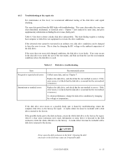
... as explained in the host computer manual. If the DC voltage level is probably not faulty. Table 6.2 System-level field troubleshooting Item DC power cable AC and DC power level Electrical noise Interface cable connection Terminating resistors Drive selection address Plug setup System cables System diagnostic test Intermittent or nonfatal errors Recommended work Check that the +12 VDC supply (pins 1 and 2 of the power connector of disk drive) is 11.4 to 12.6 VDC...
... as explained in the host computer manual. If the DC voltage level is probably not faulty. Table 6.2 System-level field troubleshooting Item DC power cable AC and DC power level Electrical noise Interface cable connection Terminating resistors Drive selection address Plug setup System cables System diagnostic test Intermittent or nonfatal errors Recommended work Check that the +12 VDC supply (pins 1 and 2 of the power connector of disk drive) is 11.4 to 12.6 VDC...
Manual/User Guide
Page 118
... user the environment conditions where the disk drive is not faulty. To check performance, change the disk drive conditions by sense data, and gives supplementary information on finding the error cause (faulty part). A media defect list must be included with troubleshooting. Replace the disk drive, and check that the test method is done by troubleshooting, return the complete disk drive to the factory. Chapter 7 error analysis by changing the voltage or temperature. If the error...
... user the environment conditions where the disk drive is not faulty. To check performance, change the disk drive conditions by sense data, and gives supplementary information on finding the error cause (faulty part). A media defect list must be included with troubleshooting. Replace the disk drive, and check that the test method is done by troubleshooting, return the complete disk drive to the factory. Chapter 7 error analysis by changing the voltage or temperature. If the error...

Manual/User Guide
Page 137
... this command, the DSP drives the voice coil motor, via the digital-to-analog converter and power amplifier, to move to a disk, the head must be correctly centered over the target cylinder. 8 - 14 C141-E103-02EN The DSP receives a position signal from the MPU. (2) Seek operation When the host issues a data read or write data from or to the target cylinder. A predetermined target speed is used...
... this command, the DSP drives the voice coil motor, via the digital-to-analog converter and power amplifier, to move to a disk, the head must be correctly centered over the target cylinder. 8 - 14 C141-E103-02EN The DSP receives a position signal from the MPU. (2) Seek operation When the host issues a data read or write data from or to the target cylinder. A predetermined target speed is used...


