Manual/User Guide
Page 6
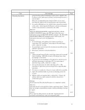
... setting device number and operation modes, mounting the disk drive, connecting the cables, and confirming drive operation. C141-E103-02EN v Chapter 8 PRINCIPLE OF OPERATION This chapter explains disk drives configuration and operation of MAH series and MAJ series disk drive. It includes the notice and procedures for operation ..., MAH3091MC/MP (hereafter, MAH series) and MAJ3364MC/MP, MAJ3182MC/MP, MAJ3091MC/MP (hereafter, MAJ series), 3.5 type fixed disk drives with an embedded SCSI controller. Chapter 2 SPECIFICATIONS This chapter gives detailed specifications of troubleshooting the...
... setting device number and operation modes, mounting the disk drive, connecting the cables, and confirming drive operation. C141-E103-02EN v Chapter 8 PRINCIPLE OF OPERATION This chapter explains disk drives configuration and operation of MAH series and MAJ series disk drive. It includes the notice and procedures for operation ..., MAH3091MC/MP (hereafter, MAH series) and MAJ3364MC/MP, MAJ3182MC/MP, MAJ3091MC/MP (hereafter, MAJ series), 3.5 type fixed disk drives with an embedded SCSI controller. Chapter 2 SPECIFICATIONS This chapter gives detailed specifications of troubleshooting the...
Manual/User Guide
Page 7
CAUTION CAUTION indicates that describes the electrical requirements of model names and product numbers, and SCSI interface functions. Indicates vi C141-E103-02EN DANGER DANGER indicates that personal injury could occur if the user does not perform the ...the locations of mounting setting terminals and connectors, a list of setting items, the signal assignments of interface connectors, lists of the SCSI interface between host system and disk drive, the data formatted at the factory and device type. NOTICE NOTICE indicates that the helps the user use the product more effectively....
CAUTION CAUTION indicates that describes the electrical requirements of model names and product numbers, and SCSI interface functions. Indicates vi C141-E103-02EN DANGER DANGER indicates that personal injury could occur if the user does not perform the ...the locations of mounting setting terminals and connectors, a list of setting items, the signal assignments of interface connectors, lists of the SCSI interface between host system and disk drive, the data formatted at the factory and device type. NOTICE NOTICE indicates that the helps the user use the product more effectively....
Manual/User Guide
Page 8
...16-bit SCSI 68 pin connector 160MHz transfer Formatted capacity (100 MB units) Disk drive size 3: 3.5 type. Fujitsu is not responsible for connecting the three device types or host system and the disk drives (Note 1). These disk drives may be called intelligent disk drives (IDD), drives, or ... MAH3091 MAH3091MC, MAH3091MP MAJ3364 MAJ3364MC, MAJ3364MP MAJ3182 MAJ3182MC, MAJ3182MP MAJ3091 MAJ3091MC, MAJ3091MP C141-E103-02EN vii Hand Disk Drive Type AH: Number of rotations 7,200min-1 (7,200rpm) AJ: Number of the SCSI, i.e., the interface for drive failures caused by misuse by the...
...16-bit SCSI 68 pin connector 160MHz transfer Formatted capacity (100 MB units) Disk drive size 3: 3.5 type. Fujitsu is not responsible for connecting the three device types or host system and the disk drives (Note 1). These disk drives may be called intelligent disk drives (IDD), drives, or ... MAH3091 MAH3091MC, MAH3091MP MAJ3364 MAJ3364MC, MAJ3364MP MAJ3182 MAJ3182MC, MAJ3182MP MAJ3091 MAJ3091MC, MAJ3091MP C141-E103-02EN vii Hand Disk Drive Type AH: Number of rotations 7,200min-1 (7,200rpm) AJ: Number of the SCSI, i.e., the interface for drive failures caused by misuse by the...
Manual/User Guide
Page 10
... while removing a PCA. To connect SCSI devices, be prevented. 2. Check that the SCSI device with the terminating resistor is required to prevent unexpected or unpredictable operation. 4. ESD (Electrostatics Discharge) may cause the damage to the disk drive, turn off before connecting or disconnecting ...Open all ventilation holes to clean a disk drive assembly. 5. Always ground yourself with the colored wire connected to the cable. This operation is the last device connected to pin 1. Caution 1. Caution 6-6 1. Fujitsu does not assume responsibility if data is...
... while removing a PCA. To connect SCSI devices, be prevented. 2. Check that the SCSI device with the terminating resistor is required to prevent unexpected or unpredictable operation. 4. ESD (Electrostatics Discharge) may cause the damage to the disk drive, turn off before connecting or disconnecting ...Open all ventilation holes to clean a disk drive assembly. 5. Always ground yourself with the colored wire connected to the cable. This operation is the last device connected to pin 1. Caution 1. Caution 6-6 1. Fujitsu does not assume responsibility if data is...
Manual/User Guide
Page 11
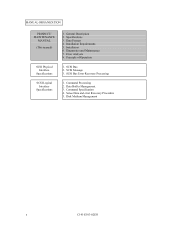
Installation 6. Diagnostics and Maintenance 7. SCSI Message 3. Command Processing 2. Principle of Operation 1. SCSI Bus 2. Data Buffer Management 3. SCSI Bus Error Recovery Processing 1. Command Specification 4. Specifications 3. Sense Data and error Recovery Procedure 5. Error Analysis 8. Disk Medium Management x C141-E103-02EN Installation Requirements 5. Data Format 4. MANUAL ORGANIZATION PRODUCT/ MAINTENANCE MANUAL (This manual) SCSI Physical Interface Specifications SCSI Logical Interface Specifications 1. General Description 2.
Installation 6. Diagnostics and Maintenance 7. SCSI Message 3. Command Processing 2. Principle of Operation 1. SCSI Bus 2. Data Buffer Management 3. SCSI Bus Error Recovery Processing 1. Command Specification 4. Specifications 3. Sense Data and error Recovery Procedure 5. Error Analysis 8. Disk Medium Management x C141-E103-02EN Installation Requirements 5. Data Format 4. MANUAL ORGANIZATION PRODUCT/ MAINTENANCE MANUAL (This manual) SCSI Physical Interface Specifications SCSI Logical Interface Specifications 1. General Description 2.
Manual/User Guide
Page 13
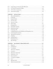
... procedures...5-10 5.5 Connecting Cables...5-11 5.6 Confirming Operations after Installation and Preparation for use 5-12 5.6.1 Confirming initial operations 5-12 5.6.2 Checking SCSI connection...5-13 5.6.3 Formatting ...5-16 5.6.4 Setting parameters ...5-18 5.7 Dismounting Drives...5-22 5.8 Spare Disk Drive ...5-22 CHAPTER 6 DIAGNOSTICS AND MAINTENANCE 6-1 6.1 Diagnostics ...6-1 6.1.1 Self-diagnostics ...6-1 6.1.2 Test programs...6-4 6.2 Maintenance Information ...6-5 6.2.1 Precautions ...6-5 6.2.2 Maintenance requirements...6-6 6.2.3 Maintenance levels ...6-8 6.2.4 Revision numbers...
... procedures...5-10 5.5 Connecting Cables...5-11 5.6 Confirming Operations after Installation and Preparation for use 5-12 5.6.1 Confirming initial operations 5-12 5.6.2 Checking SCSI connection...5-13 5.6.3 Formatting ...5-16 5.6.4 Setting parameters ...5-18 5.7 Dismounting Drives...5-22 5.8 Spare Disk Drive ...5-22 CHAPTER 6 DIAGNOSTICS AND MAINTENANCE 6-1 6.1 Diagnostics ...6-1 6.1.1 Self-diagnostics ...6-1 6.1.2 Test programs...6-4 6.2 Maintenance Information ...6-5 6.2.1 Precautions ...6-5 6.2.2 Maintenance requirements...6-6 6.2.3 Maintenance levels ...6-8 6.2.4 Revision numbers...
Manual/User Guide
Page 14
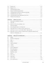
...test ...6-12 Troubleshooting Procedures 6-13 Outline of troubleshooting procedures 6-13 Troubleshooting with disk drive replacement in the field 6-13 Troubleshooting at the repair site 6-15 Troubleshooting with...data (5-2x-xx), (5-3D-00), (5-90-00), (B-47-xx), (B-49-00), (B-4D-xx) and (B-4E-00): SCSI interface error 7-4 CHAPTER 8 PRINCIPLE OF OPERATION 8-1 8.1 Outline...8-1 8.2 Disk Drive Configuration ...8-1 8.2.1 Disks...8-2 8.2.2 Heads...8-2 8.2.3 Spindle mechanism...8-2 8.2.4 Actuator...8-2 8.2.5 Air filters ...8-2 8.3 Circuit Configuration...8-3 8.4 Power-On Sequence ...8-5 8.5 ...
...test ...6-12 Troubleshooting Procedures 6-13 Outline of troubleshooting procedures 6-13 Troubleshooting with disk drive replacement in the field 6-13 Troubleshooting at the repair site 6-15 Troubleshooting with...data (5-2x-xx), (5-3D-00), (5-90-00), (B-47-xx), (B-49-00), (B-4D-xx) and (B-4E-00): SCSI interface error 7-4 CHAPTER 8 PRINCIPLE OF OPERATION 8-1 8.1 Outline...8-1 8.2 Disk Drive Configuration ...8-1 8.2.1 Disks...8-2 8.2.2 Heads...8-2 8.2.3 Spindle mechanism...8-2 8.2.4 Actuator...8-2 8.2.5 Air filters ...8-2 8.3 Circuit Configuration...8-3 8.4 Power-On Sequence ...8-5 8.5 ...
Manual/User Guide
Page 16
...1.1 MAH series MC outer view 1-5 1.2 MAH series MP outer view 1-6 1.3 MAJ series MC outer view...1-6 1.4 MAJ series MP outer view ...1-6 1.5 Disk/head configuration ...1-7 1.6 System configuration...1-9 3.1 Cylinder configuration...3-2 3.2 Spare area in cylinders ...3-5 3.3 Alternate cylinder ...3-6 3.4 Track format...3-6 3.5 Track skew/cylinder skew...filter (recommended 4-13 4.16 Connectors and terminals location (MP model 4-14 4.17 16-bit SCSI interface connector 4-15 4.18 Power supply connector (16-bit SCSI model 4-15 4.19 External operator panel connector (CN1 4-16 C141-E103-02EN xv
...1.1 MAH series MC outer view 1-5 1.2 MAH series MP outer view 1-6 1.3 MAJ series MC outer view...1-6 1.4 MAJ series MP outer view ...1-6 1.5 Disk/head configuration ...1-7 1.6 System configuration...1-9 3.1 Cylinder configuration...3-2 3.2 Spare area in cylinders ...3-5 3.3 Alternate cylinder ...3-6 3.4 Track format...3-6 3.5 Track skew/cylinder skew...filter (recommended 4-13 4.16 Connectors and terminals location (MP model 4-14 4.17 16-bit SCSI interface connector 4-15 4.18 Power supply connector (16-bit SCSI model 4-15 4.19 External operator panel connector (CN1 4-16 C141-E103-02EN xv
Manual/User Guide
Page 18
... start mode setting...5-8 5.4 Write protect setting (CN2 5-8 5.5 Setting of the SCSI interface operation mode (CN2 5-9 5.6 Setting the bus width of the SCSI interface (CN2 5-9 5.7 Default mode settings (by CHANGE DEFINITION command 5-9 5.8 Setting check list ...5-10 6.1 Self-diagnostic functions ...6-1 6.2 System-level field troubleshooting 6-14 6.3 Disk drive troubleshooting ...6-15 7.1 Definition of sense data ...7-3 8.1 MAJ3364 series, MAJ3182...
... start mode setting...5-8 5.4 Write protect setting (CN2 5-8 5.5 Setting of the SCSI interface operation mode (CN2 5-9 5.6 Setting the bus width of the SCSI interface (CN2 5-9 5.7 Default mode settings (by CHANGE DEFINITION command 5-9 5.8 Setting check list ...5-10 6.1 Self-diagnostic functions ...6-1 6.2 System-level field troubleshooting 6-14 6.3 Disk drive troubleshooting ...6-15 7.1 Definition of sense data ...7-3 8.1 MAJ3364 series, MAJ3182...
Manual/User Guide
Page 20
... X3.131 - 1986: Small Computer System Interface (SCSI), ANSI X3.131-1994: Small Computer System Interface - 2 (SCSI-2)]. IDDs are high performance large capacity 3.5 type fixed disk drives with large storage capacity. The flexibility and expandability of the SCSI, as well as the powerful command set of the intelligent disk drives (IDD). CHAPTER 1 GENERAL DESCRIPTION 1.1 Standard Features 1.2 Hardware...
... X3.131 - 1986: Small Computer System Interface (SCSI), ANSI X3.131-1994: Small Computer System Interface - 2 (SCSI-2)]. IDDs are high performance large capacity 3.5 type fixed disk drives with large storage capacity. The flexibility and expandability of the SCSI, as well as the powerful command set of the intelligent disk drives (IDD). CHAPTER 1 GENERAL DESCRIPTION 1.1 Standard Features 1.2 Hardware...
Manual/User Guide
Page 21
... • Data bus parity • Command set which have the wide transfer function suitable for Direct Access Device) requirements (Rev. 4.B) The SCSI commands can be useful with the large capacity buffer in the IDD. 1 - 2 C141-E103-02EN The IDD can manipulate data through logical block...of the physical characteristics of connectable SCSI devices on the same SCSI bus is extremely compact. For the ultra SCSI model, number of the disk drive. Such a high data transfer rate on the SCSI bus is 160 MB/s maximum in the standard 3.5 type fixed disk drive form factor, the IDD is varied...
... • Data bus parity • Command set which have the wide transfer function suitable for Direct Access Device) requirements (Rev. 4.B) The SCSI commands can be useful with the large capacity buffer in the IDD. 1 - 2 C141-E103-02EN The IDD can manipulate data through logical block...of the physical characteristics of connectable SCSI devices on the same SCSI bus is extremely compact. For the ultra SCSI model, number of the disk drive. Such a high data transfer rate on the SCSI bus is 160 MB/s maximum in the standard 3.5 type fixed disk drive form factor, the IDD is varied...

Manual/User Guide
Page 22
..., and IDD can perform continuous read/write operation when processing data blocks on the SCSI bus by the cable length, transmission characteristics of the SCSI bus and the connected SCSI device number. (5) Continuous block processing The addressing method of the disk drive. (7) Read-ahead cache feature After executing the READ command, the IDD reads automatically...
..., and IDD can perform continuous read/write operation when processing data blocks on the SCSI bus by the cable length, transmission characteristics of the SCSI bus and the connected SCSI device number. (5) Continuous block processing The addressing method of the disk drive. (7) Read-ahead cache feature After executing the READ command, the IDD reads automatically...
Manual/User Guide
Page 23
... capability which checks internal controller functions and drive operations to recover from 3.5 type disk drives by slipping the defective data block at formatting. The disk subsystem with a multiple of four within the range of spindle motor Using the SCSI command, the host system can be transferred... to 528 bytes. (13) Defective block slipping A logical data block can be obtained from errors in SCSI bus or the disk drive using its powerful retry processing. The initiator software is released from the complicated error recover processing by these error recovery...
... capability which checks internal controller functions and drive operations to recover from 3.5 type disk drives by slipping the defective data block at formatting. The disk subsystem with a multiple of four within the range of spindle motor Using the SCSI command, the host system can be transferred... to 528 bytes. (13) Defective block slipping A logical data block can be obtained from errors in SCSI bus or the disk drive using its powerful retry processing. The initiator software is released from the complicated error recover processing by these error recovery...
Manual/User Guide
Page 27
... The controller circuit uses LSIs to increase the reliability and uses a high speed microprocessing unit (MPU) to keep the air inside a disk enclosure (DE) to increase the performance of the SCSI controller. 1 - 8 C141-E103-02EN To prevent negative pressure in order to prevent errors being triggered by the mechanical lock when the...
... The controller circuit uses LSIs to increase the reliability and uses a high speed microprocessing unit (MPU) to keep the air inside a disk enclosure (DE) to increase the performance of the SCSI controller. 1 - 8 C141-E103-02EN To prevent negative pressure in order to prevent errors being triggered by the mechanical lock when the...

Manual/User Guide
Page 29
...are as follows: • SCSI ID: • LUN: 8-bit SCSI:Selectable from 0 to 7 (switch selectable) 16-bit SCSI:Selectable from 0 to 15 (switch selectable) 0 (fixed) 1 - 10 C141-E103-02EN The initiator selects one SCSI device by specifying that the whole volume of disk drive is a single logical unit,... the selectable number of peripheral device Each SCSI device on the bus has its own unique address (SCSI ID:#n in unit called as target is assigned for ...
...are as follows: • SCSI ID: • LUN: 8-bit SCSI:Selectable from 0 to 7 (switch selectable) 16-bit SCSI:Selectable from 0 to 15 (switch selectable) 0 (fixed) 1 - 10 C141-E103-02EN The initiator selects one SCSI device by specifying that the whole volume of disk drive is a single logical unit,... the selectable number of peripheral device Each SCSI device on the bus has its own unique address (SCSI ID:#n in unit called as target is assigned for ...

Manual/User Guide
Page 31
...36.4 GB 18.2 GB 9.1 GB 46.6 GB 23.3 GB 11.7 GB 5 3 2 10 5 3 14,792 14,808 13,261 188,928 to 293,888 172,032 to 293,888 10,025±0.5% 2.993 msec 0.6 ms (Read)/0.8 ms (Write) 4.7 ms (Read)/5.2 ms (Write) 11.0 ms (Read)/12.0 ms (Write) MAH3182 series MAH3091 series 18.2 GB 9.1 GB 23.4 GB 11.8 GB... Width Depth Weight Power consumption (*5) Interface Fast SCSI (Single-Ended) Fast 20 SCSI (Single-Ended) Fast 80 SCSI (LVD) Data transfer rate (*10) Disk drive SCSI Synchronous mode Logical data block length (*1) SCSI command specification Data buffer 12.5 W 30 s...
...36.4 GB 18.2 GB 9.1 GB 46.6 GB 23.3 GB 11.7 GB 5 3 2 10 5 3 14,792 14,808 13,261 188,928 to 293,888 172,032 to 293,888 10,025±0.5% 2.993 msec 0.6 ms (Read)/0.8 ms (Write) 4.7 ms (Read)/5.2 ms (Write) 11.0 ms (Read)/12.0 ms (Write) MAH3182 series MAH3091 series 18.2 GB 9.1 GB 23.4 GB 11.8 GB... Width Depth Weight Power consumption (*5) Interface Fast SCSI (Single-Ended) Fast 20 SCSI (Single-Ended) Fast 80 SCSI (LVD) Data transfer rate (*10) Disk drive SCSI Synchronous mode Logical data block length (*1) SCSI command specification Data buffer 12.5 W 30 s...

Manual/User Guide
Page 32
... having capacitance of 25pF or less can be restricted to the response speed of initiator and by transmission characteristics. (*11) The terminator power pin (SCSI connector) which supplies power to other terminators is the time for the further information. (*2) The number of up to 1.5 m. (*8) 1 on 1 connection ... (*1) The formatted capacity can use cable length of user cylinders indicates the max., and includes the alternate cylinder. See Chapter 3 for disks to completely stop from power on or start time is the time from power off or stop time is not used. C141-E103-02EN 2...
... having capacitance of 25pF or less can be restricted to the response speed of initiator and by transmission characteristics. (*11) The terminator power pin (SCSI connector) which supplies power to other terminators is the time for the further information. (*2) The number of up to 1.5 m. (*8) 1 on 1 connection ... (*1) The formatted capacity can use cable length of user cylinders indicates the max., and includes the alternate cylinder. See Chapter 3 for disks to completely stop from power on or start time is the time from power off or stop time is not used. C141-E103-02EN 2...

Manual/User Guide
Page 72
...A12 is connected to the GND, or the CN2-9 and CN2-10 are short-circuited.) A signal for driving the LED is output. 74LS06 or equivalent 150 Ω (IDD) NC1-A2 IMPORTANT This signal is temporarily ...the GND level when the micro program reads the SCSI ID immediately after the power supply to the IDD has been switched on the front panel of the disk drive. For details of command, refer to the ...IDD has been switched on the front of indication can be connected to set up the SCSI ID by short circuiting CN1-A3...
...A12 is connected to the GND, or the CN2-9 and CN2-10 are short-circuited.) A signal for driving the LED is output. 74LS06 or equivalent 150 Ω (IDD) NC1-A2 IMPORTANT This signal is temporarily ...the GND level when the micro program reads the SCSI ID immediately after the power supply to the IDD has been switched on the front panel of the disk drive. For details of command, refer to the ...IDD has been switched on the front of indication can be connected to set up the SCSI ID by short circuiting CN1-A3...

Manual/User Guide
Page 89
... is disable. *1 Setting at factory shipment CN2 11-12 (MP) Open Short (*1) CN2 11-12 (MC) Short Open (*1) Refer to Chapter 3 of the SCSI Logical Interface Specifications for details of the START/STOP UNIT command. (3) Write protect When the write protect function is enabled, writing to the... disk medium is set to the single-ended mode. Table 5.4 Write protect setting (CN2) Write protect Write operation is forcibly set to Table 5.3. When...
... is disable. *1 Setting at factory shipment CN2 11-12 (MP) Open Short (*1) CN2 11-12 (MC) Short Open (*1) Refer to Chapter 3 of the SCSI Logical Interface Specifications for details of the START/STOP UNIT command. (3) Write protect When the write protect function is enabled, writing to the... disk medium is set to the single-ended mode. Table 5.4 Write protect setting (CN2) Write protect Write operation is forcibly set to Table 5.3. When...

Manual/User Guide
Page 93
c) When the IDD status is idle, the LED remains off (when the initiator accesses the IDD via the SCSI bus, the LED lights). (2) Initial operation in Subsection 5.6.2. d) The disk drive enters the READY status in the initial self-diagnosis, the LED blinks. b) Check that motor starts with the IDD power ...check procedures after the START/STOP UNIT command is turned on the setting of each setting terminal. b) If an error is turned on the disk. Note that cables are supplied correctly (measure them with START/STOP command a) When power is turned on, the LED blinks an instant ...
c) When the IDD status is idle, the LED remains off (when the initiator accesses the IDD via the SCSI bus, the LED lights). (2) Initial operation in Subsection 5.6.2. d) The disk drive enters the READY status in the initial self-diagnosis, the LED blinks. b) Check that motor starts with the IDD power ...check procedures after the START/STOP UNIT command is turned on the setting of each setting terminal. b) If an error is turned on the disk. Note that cables are supplied correctly (measure them with START/STOP command a) When power is turned on, the LED blinks an instant ...


