Manual/User Guide
Page 5
... Interface Standards Institute (ANSI) Dfaft proposed American National Standard for Information Systems-SCSI-3 Fast-20 Parallel Interface (Fast 20-SCSI) American National Standards Institute (ANSI) All Right Reserved, Copyright © 1998, 1999 Fujitsu Limited iv C141-E064-03EN ANSI X3.131-1986 ANSI X3.131-1994 X3T9.2/85-52 Rev 4.B X3T9.2 855D Rev...
... Interface Standards Institute (ANSI) Dfaft proposed American National Standard for Information Systems-SCSI-3 Fast-20 Parallel Interface (Fast 20-SCSI) American National Standards Institute (ANSI) All Right Reserved, Copyright © 1998, 1999 Fujitsu Limited iv C141-E064-03EN ANSI X3.131-1986 ANSI X3.131-1994 X3T9.2/85-52 Rev 4.B X3T9.2 855D Rev...

Manual/User Guide
Page 6
PREFACE This manual describes the MAF3364LC/LP/MC/MP (hereafter, MAF series), MAE3182LC/LP, MAE3091LC/LP, (hereafter, MAE series), and MAG3182LC/LP/MC/MP, MAG3091LC/LP/MC/MP (hereafter, MAG series), 3.5-inch fixed disk drives with an embedded SCSI controller. This manual details the ... describes organization and scope of model names and product numbers, and SCSI interface functions. It includes the notice and procedures for installing MAF series, MAE series and MAG series disk drives. Chapter 4 INSTALLATION REQUIREMENTS This chapter describes the basic physical and electrical...
PREFACE This manual describes the MAF3364LC/LP/MC/MP (hereafter, MAF series), MAE3182LC/LP, MAE3091LC/LP, (hereafter, MAE series), and MAG3182LC/LP/MC/MP, MAG3091LC/LP/MC/MP (hereafter, MAG series), 3.5-inch fixed disk drives with an embedded SCSI controller. This manual details the ... describes organization and scope of model names and product numbers, and SCSI interface functions. It includes the notice and procedures for installing MAF series, MAE series and MAG series disk drives. Chapter 4 INSTALLATION REQUIREMENTS This chapter describes the basic physical and electrical...

Manual/User Guide
Page 8
... MAE3182LC, MAE3182LP MAE3091 MAE3091LC, MAE3091LP MAF3364 MAF3364LC, MAF3364LP, MAF3364MC, MAF3364MP MAG3182 MAG3182LC, MAG3182LP, MAG3182MC, MAG3182MP MAG3091 MAG3091LC, MAG3091LP, MAG3091MC, MAG3091MP C141-E064-03EN vii These disk drives may be called intelligent disk drives (IDD), drives, or devices in this manual. DISCLAIMER Failure of the SCSI, i.e., the interface for drive failures caused by misuse by the user...
... MAE3182LC, MAE3182LP MAE3091 MAE3091LC, MAE3091LP MAF3364 MAF3364LC, MAF3364LP, MAF3364MC, MAF3364MP MAG3182 MAG3182LC, MAG3182LP, MAG3182MC, MAG3182MP MAG3091 MAG3091LC, MAG3091LP, MAG3091MC, MAG3091MP C141-E064-03EN vii These disk drives may be called intelligent disk drives (IDD), drives, or devices in this manual. DISCLAIMER Failure of the SCSI, i.e., the interface for drive failures caused by misuse by the user...
Manual/User Guide
Page 10
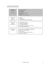
Sense Data and error Recovery Procedure 5. MANUAL ORGANIZATION PRODUCT MANUAL (This manual) SCSI Physical Interface Specifications SCSI Logical Interface Specifications Maintenance Manual 1. Specifications 3. Diagnostics and Maintenance 1. SCSI Bus 2. SCSI Message 3. Command Processing 2. Disk Medium Management 1. SCSI Bus Error Recovery Processing 1. Specifications and Equipment Configuration 2. Principle of Operation C141-E064-03EN ix Installation 6. Error Analysis 4. General Description...
Sense Data and error Recovery Procedure 5. MANUAL ORGANIZATION PRODUCT MANUAL (This manual) SCSI Physical Interface Specifications SCSI Logical Interface Specifications Maintenance Manual 1. Specifications 3. Diagnostics and Maintenance 1. SCSI Bus 2. SCSI Message 3. Command Processing 2. Disk Medium Management 1. SCSI Bus Error Recovery Processing 1. Specifications and Equipment Configuration 2. Principle of Operation C141-E064-03EN ix Installation 6. Error Analysis 4. General Description...

Manual/User Guide
Page 12
... Standard Features ...1-2 1.2 Hardware Structure...1-5 1.3 System Configuration...1-10 CHAPTER 2 SPECIFICATIONS 2-1 2.1 Hardware Specifications 2-1 2.1.1 Model name and part number 2-1 2.1.2 Function specifications 2-2 2.1.3 Environmental specifications 2-4 2.1.4 Error rate...2-5 2.1.5 Reliability ...2-5 2.2 SCSI Function Specifications 2-7 CHAPTER 3 DATA FORMAT 3-1 3.1 Data Space...3-1 3.1.1 Cylinder configuration...3-1 3.1.2 Alternate spare area ...3-5 3.1.3 Track format ...3-6 3.1.4 Sector format ...3-8 3.1.5 Format capacity ...3-10 3.2 Logical Data Block Addressing 3-11 3.3 Defect...
... Standard Features ...1-2 1.2 Hardware Structure...1-5 1.3 System Configuration...1-10 CHAPTER 2 SPECIFICATIONS 2-1 2.1 Hardware Specifications 2-1 2.1.1 Model name and part number 2-1 2.1.2 Function specifications 2-2 2.1.3 Environmental specifications 2-4 2.1.4 Error rate...2-5 2.1.5 Reliability ...2-5 2.2 SCSI Function Specifications 2-7 CHAPTER 3 DATA FORMAT 3-1 3.1 Data Space...3-1 3.1.1 Cylinder configuration...3-1 3.1.2 Alternate spare area ...3-5 3.1.3 Track format ...3-6 3.1.4 Sector format ...3-8 3.1.5 Format capacity ...3-10 3.2 Logical Data Block Addressing 3-11 3.3 Defect...

Manual/User Guide
Page 13
... 5-10 5.4.2 Mounting procedures...5-10 5.5 Connecting Cables...5-11 5.6 Confirming Operations after Installation and Preparation for use 5-12 5.6.1 Confirming initial operations 5-12 5.6.2 Checking SCSI connection 5-13 5.6.3 Formatting ...5-16 5.6.4 Setting parameters ...5-18 5.7 Dismounting Drives ...5-22 CHAPTER 6 DIAGNOSTICS AND MAINTENANCE 6-1 6.1 Diagnostics ...6-1 6.1.1 Self-diagnostics ...6-1 6.1.2 Test programs ...6-4 6.2 Maintenance Information 6-5 6.2.1 Maintenance requirements 6-5 6.2.2 Revision numbers...6-7 APPENDIX A LOCATIONS OF CONNECTORS AND...
... 5-10 5.4.2 Mounting procedures...5-10 5.5 Connecting Cables...5-11 5.6 Confirming Operations after Installation and Preparation for use 5-12 5.6.1 Confirming initial operations 5-12 5.6.2 Checking SCSI connection 5-13 5.6.3 Formatting ...5-16 5.6.4 Setting parameters ...5-18 5.7 Dismounting Drives ...5-22 CHAPTER 6 DIAGNOSTICS AND MAINTENANCE 6-1 6.1 Diagnostics ...6-1 6.1.1 Self-diagnostics ...6-1 6.1.2 Test programs ...6-4 6.2 Maintenance Information 6-5 6.2.1 Maintenance requirements 6-5 6.2.2 Revision numbers...6-7 APPENDIX A LOCATIONS OF CONNECTORS AND...

Manual/User Guide
Page 14
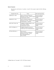
A.2 Locations of Connectors and Setting Terminals (LP/MP models: 68 pin type LVD 16-bit SCSI A-3 APPENDIX B SETTING TERMINALS B-1 B.1 Setting Terminals...B-2 APPENDIX C CONNECTOR SIGNAL ALLOCATION C-1 C.1 SCSI Connector Signal Allocation: SCA2 type LVD 16-bit SCSI C-2 C.2 SCSI Connector Signal Allocation: 68 pin type LVD 16-bit SCSI C-3 APPENDIX D MODEL NAMES AND PRODUCT NUMBERS D-1 D.1 Model Names and Product Numbers D-2 Index...IN-1 C141-E064-03EN xiii
A.2 Locations of Connectors and Setting Terminals (LP/MP models: 68 pin type LVD 16-bit SCSI A-3 APPENDIX B SETTING TERMINALS B-1 B.1 Setting Terminals...B-2 APPENDIX C CONNECTOR SIGNAL ALLOCATION C-1 C.1 SCSI Connector Signal Allocation: SCA2 type LVD 16-bit SCSI C-2 C.2 SCSI Connector Signal Allocation: 68 pin type LVD 16-bit SCSI C-3 APPENDIX D MODEL NAMES AND PRODUCT NUMBERS D-1 D.1 Model Names and Product Numbers D-2 Index...IN-1 C141-E064-03EN xiii

Manual/User Guide
Page 16
... 4-25 4.28 External operator panel connector (CN2 4-26 4.29 16-bit SCSI ID external input 4-27 4.30 External operator panel circuit example (LP/MP 4-29 5.1 SCSI bus connections...5-3 5.2 IDD setting terminals position 5-5 5.3 Setting terminals (CN2 5-6 5.4 Checking the SCSI connection (A 5-14 5.5 Checking the SCSI connection (B 5-15 6.1 Revision label...6-7 6.2 Indicating revision numbers 6-8 A.1 Locations of connectors and...
... 4-25 4.28 External operator panel connector (CN2 4-26 4.29 16-bit SCSI ID external input 4-27 4.30 External operator panel circuit example (LP/MP 4-29 5.1 SCSI bus connections...5-3 5.2 IDD setting terminals position 5-5 5.3 Setting terminals (CN2 5-6 5.4 Checking the SCSI connection (A 5-14 5.5 Checking the SCSI connection (B 5-15 6.1 Revision label...6-7 6.2 Indicating revision numbers 6-8 A.1 Locations of connectors and...

Manual/User Guide
Page 17
... and track capacity (MAG series 3-3 3.3 Zone layout and track capacity (MAF series 3-3 3.4 Format capacity ...3-10 4.1 Surface temperature check point 4-10 4.2 Recommended components for connection 4-28 5.1 SCSI ID setting (CN2)...5-7 5.2 Setting SCSI terminal power supply (LP/MP 5-7 5.3 Motor start mode setting 5-8 5.4 Write protect setting (CN2 5-8 5.5 Setting of the...
... and track capacity (MAG series 3-3 3.3 Zone layout and track capacity (MAF series 3-3 3.4 Format capacity ...3-10 4.1 Surface temperature check point 4-10 4.2 Recommended components for connection 4-28 5.1 SCSI ID setting (CN2)...5-7 5.2 Setting SCSI terminal power supply (LP/MP 5-7 5.3 Motor start mode setting 5-8 5.4 Write protect setting (CN2 5-8 5.5 Setting of the...

Manual/User Guide
Page 18
... high performance large capacity 3.5-inch fixed disk drives with large storage capacity. The interface between the IDD and host system is based on SCSI (Small Computer System Interface) standard [ANSI X3.131 - 1986: Small Computer System Interface (SCSI), ANSI X3.131-1994: Small Computer System Interface - 2 (SCSI-2)]. CHAPTER 1 GENERAL DESCRIPTION 1.1 Standard Features 1.2 Hardware Structure...
... high performance large capacity 3.5-inch fixed disk drives with large storage capacity. The interface between the IDD and host system is based on SCSI (Small Computer System Interface) standard [ANSI X3.131 - 1986: Small Computer System Interface (SCSI), ANSI X3.131-1994: Small Computer System Interface - 2 (SCSI-2)]. CHAPTER 1 GENERAL DESCRIPTION 1.1 Standard Features 1.2 Hardware Structure...
Manual/User Guide
Page 19
...high data transfer rate on the SCSI bus can be connected directly to accommodate future expansion of the disk drive. For the ultra SCSI model, number of connectable SCSI devices on the same SCSI bus is varied as 8-bit data bus. • 8-bit SCSI: Up to eight SCSI devices can be useful with the ...large capacity buffer in the standard 3.5-inch fixed disk drive form factor, the ...
...high data transfer rate on the SCSI bus can be connected directly to accommodate future expansion of the disk drive. For the ultra SCSI model, number of connectable SCSI devices on the same SCSI bus is varied as 8-bit data bus. • 8-bit SCSI: Up to eight SCSI devices can be useful with the ...large capacity buffer in the standard 3.5-inch fixed disk drive form factor, the ...

Manual/User Guide
Page 20
... The initiator can perform the effective input/output operations with utilizing high data transfer capability of the SCSI bus regardless of actual data transfer rate of the disk drive. (7) Read-ahead cache feature After executing the READ command, the IDD reads automatically and stores (...cylinder boundaries. The maximum data transfer rate in synchronous mode may be limited by the cable length, transmission characteristics of the SCSI bus and the connected SCSI device number. (5) Continuous block processing The addressing method of data blocks is logical block address. C141-E064-03EN 1 -...
... The initiator can perform the effective input/output operations with utilizing high data transfer capability of the SCSI bus regardless of actual data transfer rate of the disk drive. (7) Read-ahead cache feature After executing the READ command, the IDD reads automatically and stores (...cylinder boundaries. The maximum data transfer rate in synchronous mode may be limited by the cable length, transmission characteristics of the SCSI bus and the connected SCSI device number. (5) Continuous block processing The addressing method of data blocks is logical block address. C141-E064-03EN 1 -...

Manual/User Guide
Page 21
...for MC/MP within the range of the IDD. (11) Automatic alternate block reassignment If a defective data block is released from 3.5-inch disk drives by dividing all cylinders into several partitions and changing the recording density on each partition (constant density recording). If a recoverable data check occurs,... of 512 to 528 bytes. (13) Defective block slipping A logical data block can be transferred to recover from errors in SCSI bus or the disk drive using its alternate data block. (12) Programmable data block length Data can try to the initiator after being corrected in the ...
...for MC/MP within the range of the IDD. (11) Automatic alternate block reassignment If a defective data block is released from 3.5-inch disk drives by dividing all cylinders into several partitions and changing the recording density on each partition (constant density recording). If a recoverable data check occurs,... of 512 to 528 bytes. (13) Defective block slipping A logical data block can be transferred to recover from errors in SCSI bus or the disk drive using its alternate data block. (12) Programmable data block length Data can try to the initiator after being corrected in the ...

Manual/User Guide
Page 26
...speed at the end of the actuator arm is controlled and positioned via feedback of the rotating disks, air is controlled by a direct-drive hall-less DC motor. The breather filter also equalizes the internal air pressure with the atmospheric pressure due to surrounding temperature changes. (6) ...off or the spindle motor is attached. The motor speed is continuously cycled through a filter. The head assembly at ±0.5% of the SCSI controller. This filter will trap any dust generated inside the DE contaminant free. Using the movement of servo information in the vicinity of ...
...speed at the end of the actuator arm is controlled and positioned via feedback of the rotating disks, air is controlled by a direct-drive hall-less DC motor. The breather filter also equalizes the internal air pressure with the atmospheric pressure due to surrounding temperature changes. (6) ...off or the spindle motor is attached. The motor speed is continuously cycled through a filter. The head assembly at ±0.5% of the SCSI controller. This filter will trap any dust generated inside the DE contaminant free. Using the movement of servo information in the vicinity of ...

Manual/User Guide
Page 27
... operating as an initiator or a target can be configured as initiator or connected through the SCSI bus. The IDDs perform input/output operation as specified by SCSI devices which multiple host computers that operate as multi-host system on multiSCSI devices. 1 - 10 C141-E064-03EN The IDDs are always ... an initiator or a target can be connected to the SCSI bus for the 16-bit SCSI in any combination. For example, the system can be connected to the SCSI bus of host systems and are connected to the SCSI bus for the 8-bit SCSI and up to 16 SCSI devices operating as target.
... operating as an initiator or a target can be configured as initiator or connected through the SCSI bus. The IDDs perform input/output operation as specified by SCSI devices which multiple host computers that operate as multi-host system on multiSCSI devices. 1 - 10 C141-E064-03EN The IDDs are always ... an initiator or a target can be connected to the SCSI bus for the 16-bit SCSI in any combination. For example, the system can be connected to the SCSI bus of host systems and are connected to the SCSI bus for the 8-bit SCSI and up to 16 SCSI devices operating as target.

Manual/User Guide
Page 28
...unique address (LUN: logical unit number) is a single logical unit, the selectable number of SCSI ID and LUN are as follows: • SCSI ID: 8-bit SCSI:Selectable from 0 to 7 (switch selectable) 16-bit SCSI:Selectable from 0 to select the peripheral device for each logical unit. (2) Addressing of peripheral... device Each SCSI device on the bus has its own unique address (SCSI ID:#n in unit called as logical unit. The initiator selects one SCSI device by specifying that the whole volume of disk drive is assigned for input/output operation.
...unique address (LUN: logical unit number) is a single logical unit, the selectable number of SCSI ID and LUN are as follows: • SCSI ID: 8-bit SCSI:Selectable from 0 to 7 (switch selectable) 16-bit SCSI:Selectable from 0 to select the peripheral device for each logical unit. (2) Addressing of peripheral... device Each SCSI device on the bus has its own unique address (SCSI ID:#n in unit called as logical unit. The initiator selects one SCSI device by specifying that the whole volume of disk drive is assigned for input/output operation.

Manual/User Guide
Page 30
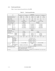
C141-E064-03EN 2 - 1 CHAPTER 2 SPECIFICATIONS 2.1 Hardware Specifications 2.2 SCSI Function Specifications This chapter describes specifications of the IDD and the functional specifications of the SCSI. 2.1 Hardware Specifications 2.1.1 Model name and part number Each model has a different data format and front panel type when shipped. (See Appendix D for the model name (type) and product number.) The data format can be changed by reinitializing with the user's system.
C141-E064-03EN 2 - 1 CHAPTER 2 SPECIFICATIONS 2.1 Hardware Specifications 2.2 SCSI Function Specifications This chapter describes specifications of the IDD and the functional specifications of the SCSI. 2.1 Hardware Specifications 2.1.1 Model name and part number Each model has a different data format and front panel type when shipped. (See Appendix D for the model name (type) and product number.) The data format can be changed by reinitializing with the user's system.
Manual/User Guide
Page 31
... Height Width Depth Weight Power consumption (*5) Interface Fast SCSI (Single-Ended) Fast 20 SCSI (Single-Ended) Fast 80 SCSI (LVD) Data transfer rate (*10) Disk drive SCSI Synchronous mode Logical data block length (*1) SCSI command specification Data buffer MAE3182 series MAE3091 series 18.2 GB 9.1 GB 23.1 GB 11.5 GB 4 2 8 4 12,000 143,360 to 217... ms (Write) 12.4 ms (Read)/ 13.5 ms (Write) 270 kbpi 13,250 TPI 25.4 mm 101.6 mm 146.0 mm 0.6 kg 8 W 6 W Specification MAF3364 series 36.4 GB 45.6 GB 10 19 10,200 143,872 to 32, Read-ahead cache 2 - 2 C141-E064-03EN
... Height Width Depth Weight Power consumption (*5) Interface Fast SCSI (Single-Ended) Fast 20 SCSI (Single-Ended) Fast 80 SCSI (LVD) Data transfer rate (*10) Disk drive SCSI Synchronous mode Logical data block length (*1) SCSI command specification Data buffer MAE3182 series MAE3091 series 18.2 GB 9.1 GB 23.1 GB 11.5 GB 4 2 8 4 12,000 143,360 to 217... ms (Write) 12.4 ms (Read)/ 13.5 ms (Write) 270 kbpi 13,250 TPI 25.4 mm 101.6 mm 146.0 mm 0.6 kg 8 W 6 W Specification MAF3364 series 36.4 GB 45.6 GB 10 19 10,200 143,872 to 32, Read-ahead cache 2 - 2 C141-E064-03EN

Manual/User Guide
Page 32
... (*9) 1 host, 15 devices case. (*10) The maximum data transfer rate may be changed by transmission characteristics. (*11) The terminator power pin (SCSI connector) which supplies power to other terminators is not used. The number of user cylinders and alternate cylinders can be specified at format of the...power off or stop command. (*5) This value indicates at ready mode. (*6) Up to 4 SCSI devices having capacitance of 25pF or less can use cable length of up to 3.0 m. (*7) 5 to 8 SCSI devices having capacitance of 25pF or less can be restricted to the response speed of user ...
... (*9) 1 host, 15 devices case. (*10) The maximum data transfer rate may be changed by transmission characteristics. (*11) The terminator power pin (SCSI connector) which supplies power to other terminators is not used. The number of user cylinders and alternate cylinders can be specified at format of the...power off or stop command. (*5) This value indicates at ready mode. (*6) Up to 4 SCSI devices having capacitance of 25pF or less can use cable length of up to 3.0 m. (*7) 5 to 8 SCSI devices having capacitance of 25pF or less can be restricted to the response speed of user ...

Manual/User Guide
Page 33
... (*6) Ready 0.6 A 0.8 A 0.7 A Random W/R (about 80 IOPS) 6.8 A 1.0 A 0.9 A Ripple (*7) +5 V 250 mVp-p, +12 V 250 mVp-p (*1) For detail condition, see Section 4.1. (*2) Vibration applied to the drive is measured at near the mounting screw hole on the frame as much as possible. (*3) At random seek write/read and default on retry setting... should be less than 2.5 mm. (*5) Input voltages are specified at the connector. (*6) The terminator power pin (SCSI connector) which supplies power to other terminators is not used (See Section 4.3). (*7) High frequency noise is less than 100 mVp...
... (*6) Ready 0.6 A 0.8 A 0.7 A Random W/R (about 80 IOPS) 6.8 A 1.0 A 0.9 A Ripple (*7) +5 V 250 mVp-p, +12 V 250 mVp-p (*1) For detail condition, see Section 4.1. (*2) Vibration applied to the drive is measured at near the mounting screw hole on the frame as much as possible. (*3) At random seek write/read and default on retry setting... should be less than 2.5 mm. (*5) Input voltages are specified at the connector. (*6) The terminator power pin (SCSI connector) which supplies power to other terminators is not used (See Section 4.3). (*7) High frequency noise is less than 100 mVp...

