
Manual/User Guide
Page 6
... operation modes, mounting the disk drive, connecting the cables, and confirming drive operation. Chapter 5 INSTALLATION This chapter explains how to do about media defects. Chapter 6 DIAGNOSIS and MAINTENANCE This chapter describes the automatic diagnosis, and maintenance of model names and product numbers, and SCSI interface functions. Chapter 2 SPECIFICATIONS This chapter gives detailed specifications of the disk, the address method, and what to install MAF series, MAE series and MAG series disk drives. Chapter 3 DATA FORMAT...
... operation modes, mounting the disk drive, connecting the cables, and confirming drive operation. Chapter 5 INSTALLATION This chapter explains how to do about media defects. Chapter 6 DIAGNOSIS and MAINTENANCE This chapter describes the automatic diagnosis, and maintenance of model names and product numbers, and SCSI interface functions. Chapter 2 SPECIFICATIONS This chapter gives detailed specifications of the disk, the address method, and what to install MAF series, MAE series and MAG series disk drives. Chapter 3 DATA FORMAT...

Manual/User Guide
Page 8
..., repairs, or replacement. The suffix of the model name of the disk drive varies depending on the electrical requirements, capacity, and data format at factory shipment of the MAF series, MAE series and MAG series intelligent disk drive is not responsible for connecting the three device types or host system and the disk drives (Note 1). DISCLAIMER Failure of the SCSI, i.e., the interface for drive failures caused by misuse by the user, poor environmental conditions, power trouble, host problems, cable failures...
..., repairs, or replacement. The suffix of the model name of the disk drive varies depending on the electrical requirements, capacity, and data format at factory shipment of the MAF series, MAE series and MAG series intelligent disk drive is not responsible for connecting the three device types or host system and the disk drives (Note 1). DISCLAIMER Failure of the SCSI, i.e., the interface for drive failures caused by misuse by the user, poor environmental conditions, power trouble, host problems, cable failures...
Manual/User Guide
Page 9
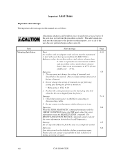
... shipped from the MAF3364xx. Fujitsu does not assume responsibility if data is turned on. • Write protect: CN2 9-10 3. Data loss 1. The user must not change the setting of terminals except following setting pins during the power is destroyed during servicing or repair. Damage 1. The RECEIVE DIAGNOSTIC RESULTS command cannot read out the error information detected in this manual are as follows: Task Mounting Installation A hazarous situation could result...
... shipped from the MAF3364xx. Fujitsu does not assume responsibility if data is turned on. • Write protect: CN2 9-10 3. Data loss 1. The user must not change the setting of terminals except following setting pins during the power is destroyed during servicing or repair. Damage 1. The RECEIVE DIAGNOSTIC RESULTS command cannot read out the error information detected in this manual are as follows: Task Mounting Installation A hazarous situation could result...
Manual/User Guide
Page 10
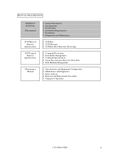
... 2. Command Specification 4. Disk Medium Management 1. Specifications and Equipment Configuration 2. Removal and Replacement Procedures 5. Installation Requirements 5. Maintenance and Diagnostics 3. SCSI Bus Error Recovery Processing 1. SCSI Message 3. Error Analysis 4. Data Format 4. Diagnostics and Maintenance 1. Data Buffer Management 3. Sense Data and error Recovery Procedure 5. Principle of Operation C141-E064-03EN ix General Description 2. Specifications 3. MANUAL ORGANIZATION PRODUCT MANUAL (This manual) SCSI Physical Interface Specifications SCSI...
... 2. Command Specification 4. Disk Medium Management 1. Specifications and Equipment Configuration 2. Removal and Replacement Procedures 5. Installation Requirements 5. Maintenance and Diagnostics 3. SCSI Bus Error Recovery Processing 1. SCSI Message 3. Error Analysis 4. Data Format 4. Diagnostics and Maintenance 1. Data Buffer Management 3. Sense Data and error Recovery Procedure 5. Principle of Operation C141-E064-03EN ix General Description 2. Specifications 3. MANUAL ORGANIZATION PRODUCT MANUAL (This manual) SCSI Physical Interface Specifications SCSI...

Manual/User Guide
Page 13
... pin connector 16-bit model (LP/MP 4-16 SCA2 type SCSI model (LC/MC 4-24 Cable connector requirements 4-28 External operator panel 4-29 CHAPTER 5 INSTALLATION 5-1 5.1 Notes on Handling Drives 5-1 5.2 Connections...5-3 5.3 Setting Terminals...5-5 5.3.1 SCSI ID setting...5-6 5.3.2 Each mode setting ...5-7 5.3.3 Mode settings ...5-9 5.4 Mounting Drives ...5-10 5.4.1 Check before mounting 5-10 5.4.2 Mounting procedures...5-10 5.5 Connecting Cables...5-11 5.6 Confirming Operations after Installation and Preparation for use 5-12 5.6.1 Confirming initial operations 5-12 5.6.2 Checking SCSI...
... pin connector 16-bit model (LP/MP 4-16 SCA2 type SCSI model (LC/MC 4-24 Cable connector requirements 4-28 External operator panel 4-29 CHAPTER 5 INSTALLATION 5-1 5.1 Notes on Handling Drives 5-1 5.2 Connections...5-3 5.3 Setting Terminals...5-5 5.3.1 SCSI ID setting...5-6 5.3.2 Each mode setting ...5-7 5.3.3 Mode settings ...5-9 5.4 Mounting Drives ...5-10 5.4.1 Check before mounting 5-10 5.4.2 Mounting procedures...5-10 5.5 Connecting Cables...5-11 5.6 Confirming Operations after Installation and Preparation for use 5-12 5.6.1 Confirming initial operations 5-12 5.6.2 Checking SCSI...
Manual/User Guide
Page 31
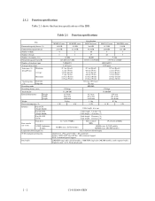
... the function specifications of rotations (rpm) Average latency time Seek time (*3) (Read/Write) Minimum Average Maximum Start/stop time Start time (*4) Stop time Recording mode Recording density (max) Track density External dimensions Height Width Depth Weight Power consumption (*5) Interface Fast SCSI (Single-Ended) Fast 20 SCSI (Single-Ended) Fast 80 SCSI (LVD) Data transfer rate (*10) Disk drive SCSI Synchronous mode Logical data block length (*1) SCSI command specification Data buffer MAE3182 series MAE3091 series 18.2 GB 9.1 GB 23.1 GB 11.5 GB 4 2 8 4 12...
... the function specifications of rotations (rpm) Average latency time Seek time (*3) (Read/Write) Minimum Average Maximum Start/stop time Start time (*4) Stop time Recording mode Recording density (max) Track density External dimensions Height Width Depth Weight Power consumption (*5) Interface Fast SCSI (Single-Ended) Fast 20 SCSI (Single-Ended) Fast 80 SCSI (LVD) Data transfer rate (*10) Disk drive SCSI Synchronous mode Logical data block length (*1) SCSI command specification Data buffer MAE3182 series MAE3091 series 18.2 GB 9.1 GB 23.1 GB 11.5 GB 4 2 8 4 12...

Manual/User Guide
Page 32
... 12000 Seek Difference MAE series/MAG series MAF series (*4) The start time is the time from power on 1 connection case. (*9) 1 host, 15 devices case. (*10) The maximum data transfer rate may be changed by transmission characteristics. (*11) The terminator power pin (SCSI connector) which supplies power to other terminators is the time for the further information. (*2) The number of initiator and by changing the logical block length and using spare sector space. C141-E064-03EN 2 - 3 (*1) The formatted capacity can use cable...
... 12000 Seek Difference MAE series/MAG series MAF series (*4) The start time is the time from power on 1 connection case. (*9) 1 host, 15 devices case. (*10) The maximum data transfer rate may be changed by transmission characteristics. (*11) The terminator power pin (SCSI connector) which supplies power to other terminators is the time for the further information. (*2) The number of initiator and by changing the logical block length and using spare sector space. C141-E064-03EN 2 - 3 (*1) The formatted capacity can use cable...

Manual/User Guide
Page 33
.... (*3) At random seek write/read and default on retry setting with log sweep vibration. (*4) At power-off state after installation Vibration displacement should be less than 2.5 mm. (*5) Input voltages are specified at the connector. (*6) The terminator power pin (SCSI connector) which supplies power to other terminators is not used (See Section 4.3). (*7) High frequency noise is less than 100 mVp-p. 2 - 4 C141-E064-03EN 2.1.3 Environmental specifications Table 2.2 lists environmental...
.... (*3) At random seek write/read and default on retry setting with log sweep vibration. (*4) At power-off state after installation Vibration displacement should be less than 2.5 mm. (*5) Input voltages are specified at the connector. (*6) The terminator power pin (SCSI connector) which supplies power to other terminators is not used (See Section 4.3). (*7) High frequency noise is less than 100 mVp-p. 2 - 4 C141-E064-03EN 2.1.3 Environmental specifications Table 2.2 lists environmental...
Manual/User Guide
Page 34
... or less. Mishandling by the operator, failures due to bad environmental conditions, power trouble, host system trouble, cable failures, or other failures not caused by the equipment are not considered. (2) Mean Time To Repair (MTTR) MTTR is the average time taken by a well-trained service mechanic to be accessed should be distributed over the disk medium equally. (1) Unrecoverable error rate Errors which cannot be recovered within 63...
... or less. Mishandling by the operator, failures due to bad environmental conditions, power trouble, host system trouble, cable failures, or other failures not caused by the equipment are not considered. (2) Mean Time To Repair (MTTR) MTTR is the average time taken by a well-trained service mechanic to be accessed should be distributed over the disk medium equally. (1) Unrecoverable error rate Errors which cannot be recovered within 63...

Manual/User Guide
Page 47
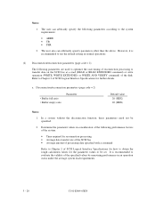
... Format capacity (GB) 18.2 9.1 36.4 18.2 9.1 Note: Total number of spare sectors is the general formula to the logical data block or the size of tracks (heads) - Table 3.4 lists examples of the format capacity when the typical logical data block length and the default spare area are specified with the parameter in the MODE SELECT or MODE SELECT EXTENDED command. [Format capacity] = [logical data block length] × [number of logical data blocks] The logical data...
... Format capacity (GB) 18.2 9.1 36.4 18.2 9.1 Note: Total number of spare sectors is the general formula to the logical data block or the size of tracks (heads) - Table 3.4 lists examples of the format capacity when the typical logical data block length and the default spare area are specified with the parameter in the MODE SELECT or MODE SELECT EXTENDED command. [Format capacity] = [logical data block length] × [number of logical data blocks] The logical data...

Manual/User Guide
Page 73
(5) External operator panel connector Signals a. 16-bit SCSI -ID3, -ID2, -ID1, -ID0: Input signals (CN1-A1, A3, A5, A7 pin and CN202, 04, 06, 08 pin) These signals are used for providing switches to set the SCSI ID of the IDD externally. For the recommended circuit examples, see Subsection 4.3.4. 4 - 20 Figure 4.23 16-bit SCSI ID external input C141-E064-03EN Figure 4.23 shows the electrical requirements.
(5) External operator panel connector Signals a. 16-bit SCSI -ID3, -ID2, -ID1, -ID0: Input signals (CN1-A1, A3, A5, A7 pin and CN202, 04, 06, 08 pin) These signals are used for providing switches to set the SCSI ID of the IDD externally. For the recommended circuit examples, see Subsection 4.3.4. 4 - 20 Figure 4.23 16-bit SCSI ID external input C141-E064-03EN Figure 4.23 shows the electrical requirements.

Manual/User Guide
Page 80
Figure 4.29 shows the electrical requirements. (IDD) CN2-08 CN2-06 CN2-04 CN2-02 Figure 4.29 16-bit SCSI ID external input C141-E064-03EN 4 - 27 (4) External operator panel connector Signals a. 16-bit SCSI -ID3, -ID2, -ID1, -ID0: Input signals (CN-2-02, 04, 06, 08 pin) These signals are used for providing switches to set the SCSI ID of the IDD externally.
Figure 4.29 shows the electrical requirements. (IDD) CN2-08 CN2-06 CN2-04 CN2-02 Figure 4.29 16-bit SCSI ID external input C141-E064-03EN 4 - 27 (4) External operator panel connector Signals a. 16-bit SCSI -ID3, -ID2, -ID1, -ID0: Input signals (CN-2-02, 04, 06, 08 pin) These signals are used for providing switches to set the SCSI ID of the IDD externally.
Manual/User Guide
Page 84
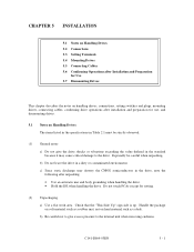
... the specifications in Table 2.1 must be careful when unpacking. b) Do not leave the drive in the drive, note the following after installation and preparation for setting. (2) Unpackaging a) Use a flat work area. CHAPTER 5 INSTALLATION 5.1 Notes on Handling Drives 5.2 Connections 5.3 Setting Terminals 5.4 Mounting Drives 5.5 Connecting Cables 5.6 Confirming Operations after Installation and Preparation for Use 5.7 Dismounting Drives This chapter describes the notes on handling drives, connections, setting switches and plugs, mounting drives, connecting cables, confirming drive...
... the specifications in Table 2.1 must be careful when unpacking. b) Do not leave the drive in the drive, note the following after installation and preparation for setting. (2) Unpackaging a) Use a flat work area. CHAPTER 5 INSTALLATION 5.1 Notes on Handling Drives 5.2 Connections 5.3 Setting Terminals 5.4 Mounting Drives 5.5 Connecting Cables 5.6 Confirming Operations after Installation and Preparation for Use 5.7 Dismounting Drives This chapter describes the notes on handling drives, connections, setting switches and plugs, mounting drives, connecting cables, confirming drive...
Manual/User Guide
Page 99
... the setting of cylinders in the system. The user can change the following items for further details. In this case, the number of SCSI Logical Interface Specifications for further details. (1) MODE SELECT/MODE SELECT EXTENDED command Specify the format attributes on the disk with a specific (default) data format for a recoverable error. Refer to the terminating resistor. To explicitly specify the number of logical data blocks, specify the number in the format parameter (page code = 3) and drive parameter (page code = 4). 5 - 16...
... the setting of cylinders in the system. The user can change the following items for further details. In this case, the number of SCSI Logical Interface Specifications for further details. (1) MODE SELECT/MODE SELECT EXTENDED command Specify the format attributes on the disk with a specific (default) data format for a recoverable error. Refer to the terminating resistor. To explicitly specify the number of logical data blocks, specify the number in the format parameter (page code = 3) and drive parameter (page code = 4). 5 - 16...

Manual/User Guide
Page 101
This enables the IDD to the user. To obtain the best performance, set the parameters in this section is performed by the FORMAT UNIT command, the saved value of parameters described in consideration of the IDD, the saving operation for all IDs. At factory shipment of the system requirements specific to operate by using the parameter value set or saved with the MODE SELECT or MODE SELECT EXTENDED command: • Error recovery parameter • Disconnection...
This enables the IDD to the user. To obtain the best performance, set the parameters in this section is performed by the FORMAT UNIT command, the saved value of parameters described in consideration of the IDD, the saving operation for all IDs. At factory shipment of the system requirements specific to operate by using the parameter value set or saved with the MODE SELECT or MODE SELECT EXTENDED command: • Error recovery parameter • Disconnection...
Manual/User Guide
Page 103
... specified values by measuring performance in normal operations. (2) Disconnection/reconnection parameters (page code = 2) The following parameters according to Chapter 2 of the disk. The user also can arbitrarily specify the following parameters are used to optimize the start timing of reconnection processing to transfer data on the SCSI bus at a read (READ or READ EXTENDED command) or write operation (WRITE, WRITE EXTENDED, or WRITE AND VERIFY command) of SCSI Logical Interface Specifications for the parameter values to obtain...
... specified values by measuring performance in normal operations. (2) Disconnection/reconnection parameters (page code = 2) The following parameters according to Chapter 2 of the disk. The user also can arbitrarily specify the following parameters are used to optimize the start timing of reconnection processing to transfer data on the SCSI bus at a read (READ or READ EXTENDED command) or write operation (WRITE, WRITE EXTENDED, or WRITE AND VERIFY command) of SCSI Logical Interface Specifications for the parameter values to obtain...

Manual/User Guide
Page 105
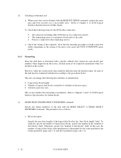
... or abort remaining suspended commands after sense pending state Disabling tagged command queuing Default value 0 (Ordering is executed by read command only.) 0 (command is difficult to check the setting terminals, change the setting, or change the drive depends on dismounting the drive. f) To store or transport the drive, keep it is resumed) 0 (enabled) 5.7 Dismounting Drives Since dismounting the drive to access the connector position, the cable may be determined in...
... or abort remaining suspended commands after sense pending state Disabling tagged command queuing Default value 0 (Ordering is executed by read command only.) 0 (command is difficult to check the setting terminals, change the setting, or change the drive depends on dismounting the drive. f) To store or transport the drive, keep it is resumed) 0 (enabled) 5.7 Dismounting Drives Since dismounting the drive to access the connector position, the cable may be determined in...

Manual/User Guide
Page 111
...and repairs Fujitsu has the service system and repair facility for replacing or repairing the disk drive. Contact Fujitsu representative to submit information for the disk drive. The DE cannot be included: a) IDD model, part number (P/N), revision number, serial number (S/N), and date of manufacturing b) Error status • Date when the error occurred • System configuration • Environmental conditions (temperature, humidity, and voltage) c) Error history d) Error contents • Outline of inconvenience • Issued commands and specified parameters • Sense data •...
...and repairs Fujitsu has the service system and repair facility for replacing or repairing the disk drive. Contact Fujitsu representative to submit information for the disk drive. The DE cannot be included: a) IDD model, part number (P/N), revision number, serial number (S/N), and date of manufacturing b) Error status • Date when the error occurred • System configuration • Environmental conditions (temperature, humidity, and voltage) c) Error history d) Error contents • Outline of inconvenience • Issued commands and specified parameters • Sense data •...
Manual/User Guide
Page 129
...29 External operator panel connector 4-18, 4-19 External operator panel connector signals 4-20 F FG 4-29 FORMAT UNIT command 5-17 Format capacity 3-10 Format parameter 5-17 Function specifications 2-2 G G list 3-12 G1 3-8 Gaps 3-8 General description 1-1 General notes 5-1 H Hardware function test 6-2 Head configuration 1-8 Heads 1-8 High speed data transfer 1-2 High speed positioning 1-4 Humidity 2-4 I Indicating revision number 6-7 Initial self-diagnostics 6-2 Input signal 4-20 Installation 5-1, 5-2 Installation requirements 4-1 Interface connector 4-17 Interface test 6-5 Internal test space...
...29 External operator panel connector 4-18, 4-19 External operator panel connector signals 4-20 F FG 4-29 FORMAT UNIT command 5-17 Format capacity 3-10 Format parameter 5-17 Function specifications 2-2 G G list 3-12 G1 3-8 Gaps 3-8 General description 1-1 General notes 5-1 H Hardware function test 6-2 Head configuration 1-8 Heads 1-8 High speed data transfer 1-2 High speed positioning 1-4 Humidity 2-4 I Indicating revision number 6-7 Initial self-diagnostics 6-2 Input signal 4-20 Installation 5-1, 5-2 Installation requirements 4-1 Interface connector 4-17 Interface test 6-5 Internal test space...

Manual/User Guide
Page 130
...S SA space 3-4 SB 3-8 SCA2 type SCSI model 4-24 SCSI ID 1-11 SCSI ID external input 4-20 SCSI bus configuration 1-10 SCSI bus connection 5-3 SCSI bus test 6-5 SCSI connector 4-17, 4-25 SCSI function specifications 2-7 SCSI/CCS standard 1-2 SG 4-29 SG terminal 4-18 Sector format 3-8 Sector slip treatment 3-12 Seek test 6-2 Self-diagnostics 6-1 Sequential read test 6-5 Sequential starting of spindle motor 4-15 Service clearance area 4-11 Service life 2-6, 6-5 Service system and repairs 6-6 Setting SCSI terminal 5-7 Setting SCSI terminal power supply 5-7 Setting check list 5-10 Setting parameters...
...S SA space 3-4 SB 3-8 SCA2 type SCSI model 4-24 SCSI ID 1-11 SCSI ID external input 4-20 SCSI bus configuration 1-10 SCSI bus connection 5-3 SCSI bus test 6-5 SCSI connector 4-17, 4-25 SCSI function specifications 2-7 SCSI/CCS standard 1-2 SG 4-29 SG terminal 4-18 Sector format 3-8 Sector slip treatment 3-12 Seek test 6-2 Self-diagnostics 6-1 Sequential read test 6-5 Sequential starting of spindle motor 4-15 Service clearance area 4-11 Service life 2-6, 6-5 Service system and repairs 6-6 Setting SCSI terminal 5-7 Setting SCSI terminal power supply 5-7 Setting check list 5-10 Setting parameters...


