
English Manual.
Page 1
Q57M Series Motherboard User's Manual
Q57M Series Motherboard User's Manual
English Manual.
Page 2
... may exist. All trade names are registered trademarks of this product. WEEE: The use motherboard better, and tells you want more detailed information about our products, please visit Foxconn's website: http://www.foxconnchannel.com © All rights reserved. For more information about ... health, which could otherwise be changed or modified at any time, Foxconn does not obligate itself to inform the user of their respective owners. Trademark: All trademarks are for Q57M Series motherboard. Although the information in this product may be caused by inappropriate waste...
... may exist. All trade names are registered trademarks of this product. WEEE: The use motherboard better, and tells you want more detailed information about our products, please visit Foxconn's website: http://www.foxconnchannel.com © All rights reserved. For more information about ... health, which could otherwise be changed or modified at any time, Foxconn does not obligate itself to inform the user of their respective owners. Trademark: All trademarks are for Q57M Series motherboard. Although the information in this product may be caused by inappropriate waste...

English Manual.
Page 3
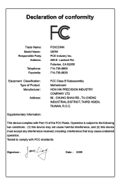
declares that the product Motherboard Q57M is in conformity with (reference to the specification under which conformity is declared in accordance with 89/336 EEC-EMC Directive) ■ EN 55022: 1998/...
declares that the product Motherboard Q57M is in conformity with (reference to the specification under which conformity is declared in accordance with 89/336 EEC-EMC Directive) ■ EN 55022: 1998/...
English Manual.
Page 4
... Rules. Lambert Rd. Declaration of conformity Trade Name: Model Name: Responsible Party: Address: Telephone: Facsimile: FOXCONN Q57M PCE Industry Inc. 458 E. Operation is subject to comply with Part 15 of Product: Manufacturer: Address: FCC Class B Subassembly Motherboard HON HAI PRECISION INDUSTRY COMPANY LTD 66 , CHUNG SHAN RD., TU-CHENG INDUSTRIAL DISTRICT, TAIPEI HSIEN...
... Rules. Lambert Rd. Declaration of conformity Trade Name: Model Name: Responsible Party: Address: Telephone: Facsimile: FOXCONN Q57M PCE Industry Inc. 458 E. Operation is subject to comply with Part 15 of Product: Manufacturer: Address: FCC Class B Subassembly Motherboard HON HAI PRECISION INDUSTRY COMPANY LTD 66 , CHUNG SHAN RD., TU-CHENG INDUSTRIAL DISTRICT, TAIPEI HSIEN...
English Manual.
Page 5
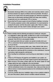
... make sure the power supply AC input voltage setting has been configured to the local standard. ■ To prevent damage to the motherboard, do not allow screws to come in serious damage to get the best performance. ■ Before turning on the power, please make... sure there are no leftover screws or metal components placed on the motherboard. Never turn on the overclocking capac- Incorrect connections might damage the motherboard. ■ When handling the motherboard, avoid touching any installation steps or have a problem related to the use of your ...
... make sure the power supply AC input voltage setting has been configured to the local standard. ■ To prevent damage to the motherboard, do not allow screws to come in serious damage to get the best performance. ■ Before turning on the power, please make... sure there are no leftover screws or metal components placed on the motherboard. Never turn on the overclocking capac- Incorrect connections might damage the motherboard. ■ When handling the motherboard, avoid touching any installation steps or have a problem related to the use of your ...

English Manual.
Page 8
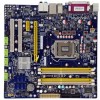
This chapter includes the following information: ■ Product Specifications ■ Layout ■ Back Panel Connectors With advanced overclocking capability and a range of connectivity features for buying Foxconn Q57M Series motherboard. Thank you for today multi-media computing requirements, Q57M enables you to maximize computing power, providing only what you need for break-through performance. Foxconn products are engineered to unleash more power from your computer.
This chapter includes the following information: ■ Product Specifications ■ Layout ■ Back Panel Connectors With advanced overclocking capability and a range of connectivity features for buying Foxconn Q57M Series motherboard. Thank you for today multi-media computing requirements, Q57M enables you to maximize computing power, providing only what you need for break-through performance. Foxconn products are engineered to unleash more power from your computer.
English Manual.
Page 11
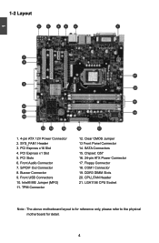
... Front Panel Connector 14. SATA Connectors 15. PCI Express x16 Slot 4. SYS_FAN1 Header 3. PCI Slots 6. Front USB Connectors 10. LGA1156 CPU Socket Note : The above motherboard layout is for reference only, please refer to the physical...
... Front Panel Connector 14. SATA Connectors 15. PCI Express x16 Slot 4. SYS_FAN1 Header 3. PCI Slots 6. Front USB Connectors 10. LGA1156 CPU Socket Note : The above motherboard layout is for reference only, please refer to the physical...
English Manual.
Page 14
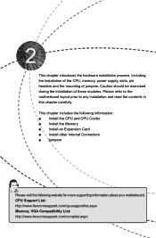
CPU Support List: http://www.foxconnsupport.com/cpusupportlist.aspx Memory, VGA Compatibility List: http://www.foxconnsupport.com/complist.aspx Please refer to the motherboard layout prior to any installation and read the contents in this chapter carefully. This chapter introduces the hardware installation process, including the installation of the ... the Memory ■ Install an Expansion Card ■ Install other Internal Connectors ■ Jumpers Please visit the following website for more supporting information about your motherboard.
CPU Support List: http://www.foxconnsupport.com/cpusupportlist.aspx Memory, VGA Compatibility List: http://www.foxconnsupport.com/complist.aspx Please refer to the motherboard layout prior to any installation and read the contents in this chapter carefully. This chapter introduces the hardware installation process, including the installation of the ... the Memory ■ Install an Expansion Card ■ Install other Internal Connectors ■ Jumpers Please visit the following website for more supporting information about your motherboard.
English Manual.
Page 15
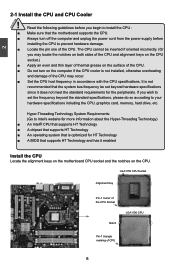
...for HT Technology ■ A BIOS that supports HT Technology and has it enabled Install the CPU Locate the alignment keys on the motherboard CPU socket and the notches on the computer if the CPU cooler is optimized for the peripherals. It is not recommended that is ... system that the system bus frequency be inserted if oriented incorrectly. (Or you begin to install the CPU : ■ Make sure that the motherboard supports the CPU. ■ Always turn on the CPU. Hyper-Threading Technology System Requirements: (Go to your hardware specifications including the CPU, graphics...
...for HT Technology ■ A BIOS that supports HT Technology and has it enabled Install the CPU Locate the alignment keys on the motherboard CPU socket and the notches on the computer if the CPU cooler is optimized for the peripherals. It is not recommended that is ... system that the system bus frequency be inserted if oriented incorrectly. (Or you begin to install the CPU : ■ Make sure that the motherboard supports the CPU. ■ Always turn on the CPU. Hyper-Threading Technology System Requirements: (Go to your hardware specifications including the CPU, graphics...
English Manual.
Page 17
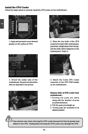
...10 10 Attach the 4-wire CPU cooler connector to the CPU FAN header on the motherboard . 3 2 1 Release bolts of CPU cooler from motherboard : 1.Turning the push pin (bolt) along with the direction of the motherboard, push them straight down from the top, and the bolts will be fixed as depicted... up. 3. Place the four bolts of the CPU cooler to correctly install the CPU cooler on the surface of the motherboard, the push pin should be fastened on the motherboard. Install the CPU Cooler Follow the steps below to the holes of arrow (counterclockwise). 2. Check the solder side of ...
...10 10 Attach the 4-wire CPU cooler connector to the CPU FAN header on the motherboard . 3 2 1 Release bolts of CPU cooler from motherboard : 1.Turning the push pin (bolt) along with the direction of the motherboard, push them straight down from the top, and the bolts will be fixed as depicted... up. 3. Place the four bolts of the CPU cooler to correctly install the CPU cooler on the surface of the motherboard, the push pin should be fastened on the motherboard. Install the CPU Cooler Follow the steps below to the holes of arrow (counterclockwise). 2. Check the solder side of ...
English Manual.
Page 18
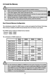
...in each pair of the same capacity, brand, speed, and chips be installed in only one direction. Single Channel - - For this motherboard, DIMM(1,2), DIMM(3,4) are : Single Channel DIMM1 DS/SS DIMM2 - White DIMM can be used. ■ Always turn off the ...(Please refer to the silkscreen next to the DIMM slots to insert the memory, switch the direction. 2 Dual Channel Memory Configuration This motherboard provides Four DDR3 memory sockets and supports Dual Channel Technology. DIMM3 - Dual Channel - Single Channel - - Read the following guidelines before...
...in each pair of the same capacity, brand, speed, and chips be installed in only one direction. Single Channel - - For this motherboard, DIMM(1,2), DIMM(3,4) are : Single Channel DIMM1 DS/SS DIMM2 - White DIMM can be used. ■ Always turn off the ...(Please refer to the silkscreen next to the DIMM slots to insert the memory, switch the direction. 2 Dual Channel Memory Configuration This motherboard provides Four DDR3 memory sockets and supports Dual Channel Technology. DIMM3 - Dual Channel - Single Channel - - Read the following guidelines before...
English Manual.
Page 19
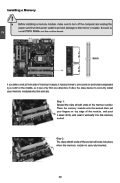
..., make sure to turn off the computer and unplug the power cord from the power outlet to prevent damage to install DDR3 DIMMs on this motherboard. Be sure to the memory module.
..., make sure to turn off the computer and unplug the power cord from the power outlet to prevent damage to install DDR3 DIMMs on this motherboard. Be sure to the memory module.
English Manual.
Page 20
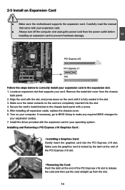
... Express x16 Graphics Card : • Installing a Graphics Card: Gently insert the graphics card into the slot. 4. CAUTION 2 2-3 Install an Expansion Card ! ■ Make sure the motherboard supports the expansion card. Remove the metal slot cover from the power outlet before installing an expansion card to the chassis back panel with the...
... Express x16 Graphics Card : • Installing a Graphics Card: Gently insert the graphics card into the slot. 4. CAUTION 2 2-3 Install an Expansion Card ! ■ Make sure the motherboard supports the expansion card. Remove the metal slot cover from the power outlet before installing an expansion card to the chassis back panel with the...

English Manual.
Page 21
... sure it is the ATX power supply connector. We recommend you using a 20-pin power supply, you are properly aligned with the connector on the motherboard. Make sure that the power supply cable and pins are using a 24-pin power supply. Firmly plug the power supply cable into the connector and... been installed properly before applying the power supply. 24-pin ATX Power Connector : PWR1 PWR1 is secure. 2 CAUTION 2-4 Install other Internal Connectors Power Connectors This motherboard uses an ATX power supply.
... sure it is the ATX power supply connector. We recommend you using a 20-pin power supply, you are properly aligned with the connector on the motherboard. Make sure that the power supply cable and pins are using a 24-pin power supply. Firmly plug the power supply cable into the connector and... been installed properly before applying the power supply. 24-pin ATX Power Connector : PWR1 PWR1 is secure. 2 CAUTION 2-4 Install other Internal Connectors Power Connectors This motherboard uses an ATX power supply.
English Manual.
Page 22
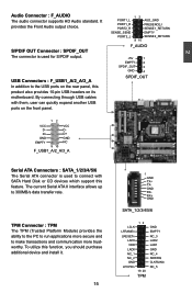
... is used for S/PDIF output. D- USB Connectors : F_USB1_A/2_A/3_A In addition to connect with them, user can quickly expand another USB ports on its motherboard. PORT1_L PORT1_R PORT2_R SENSE_SEND PORT2_L 12 AUD_GND PRESENCEJ SENSE1_RETURN EMPTY SENSE2_RETURN 9 10 F_AUDIO +5V 1 EMPTY 2 SPDIF_OUT 3 GND 4 SPDIF_OUT 12 VCC VCC D- D+ D+ GND GND EMPTY NC...
... is used for S/PDIF output. D- USB Connectors : F_USB1_A/2_A/3_A In addition to connect with them, user can quickly expand another USB ports on its motherboard. PORT1_L PORT1_R PORT2_R SENSE_SEND PORT2_L 12 AUD_GND PRESENCEJ SENSE1_RETURN EMPTY SENSE2_RETURN 9 10 F_AUDIO +5V 1 EMPTY 2 SPDIF_OUT 3 GND 4 SPDIF_OUT 12 VCC VCC D- D+ D+ GND GND EMPTY NC...

English Manual.
Page 23
...off mode (S5), the LED is pressed. Power LED Connector (PWR-LED) Connect to be turned on the front panel of the chassis. Push this motherboard. PWR-LED - RESET-SW PWR-SW NC EMPTY 9 10 FP1 1 GND POWER SENSE CONTROL CPU_FAN/SYS_FAN1 12 RLSD SIN SOUT DTR GND DSR RTS CTS...speed can be controlled and monitored in S3/S4 sleep state or power off . This 2-pin connector is blinking; When the system is in the motherboard. 12 + + HDD-LED - Fan Connectors : CPU_FAN, SYS_FAN1 There are two main fan headers on . 2 Front Panel Connector : FP1 This...
...off mode (S5), the LED is pressed. Power LED Connector (PWR-LED) Connect to be turned on the front panel of the chassis. Push this motherboard. PWR-LED - RESET-SW PWR-SW NC EMPTY 9 10 FP1 1 GND POWER SENSE CONTROL CPU_FAN/SYS_FAN1 12 RLSD SIN SOUT DTR GND DSR RTS CTS...speed can be controlled and monitored in S3/S4 sleep state or power off . This 2-pin connector is blinking; When the system is in the motherboard. 12 + + HDD-LED - Fan Connectors : CPU_FAN, SYS_FAN1 There are two main fan headers on . 2 Front Panel Connector : FP1 This...
English Manual.
Page 24
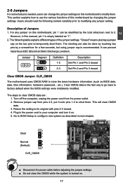
...following table explains different types of the jumper settings. The shorting can prevent hazardous ESD (Electrical Static Discharge) problem. Description of this motherboard to short them. "Closed" means placing a jumper cap on the two pins to factory default when the BIOS settings were mistakenly ... put it onto pins 1-2 to modify them . Go to BIOS Setup to its original with pins 2-3 closed Clear CMOS Jumper: CLR_CMOS The motherboard uses CMOS RAM to use the various functions of Jumpers 1. 2 2-5 Jumpers For some features needed, users can be done by touching two ...
...following table explains different types of the jumper settings. The shorting can prevent hazardous ESD (Electrical Static Discharge) problem. Description of this motherboard to short them. "Closed" means placing a jumper cap on the two pins to factory default when the BIOS settings were mistakenly ... put it onto pins 1-2 to modify them . Go to BIOS Setup to its original with pins 2-3 closed Clear CMOS Jumper: CLR_CMOS The motherboard uses CMOS RAM to use the various functions of Jumpers 1. 2 2-5 Jumpers For some features needed, users can be done by touching two ...

English Manual.
Page 25
... management features such as Intel® AMT, that allows to enable or disable Intel® Management Engine function. 2 CAUTION Intel® ME Jumper: MFG This motherboard uses MFG jumper to improve management of corporate assets.
... management features such as Intel® AMT, that allows to enable or disable Intel® Management Engine function. 2 CAUTION Intel® ME Jumper: MFG This motherboard uses MFG jumper to improve management of corporate assets.
English Manual.
Page 31
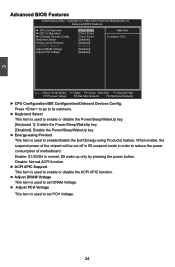
.... 24 When enable, the suspend power of the chipset will be cut off in S5 suspend mode in order to reduce the power consumption of motherboard. 3 Advanced BIOS Features CMOS Setup Utility - Advanced BIOS Features ► CPU Configuration ► IDE Configuration ► Onboard Devices Config. Copyright (C) 1985-2009, American Megatrends, Inc...
.... 24 When enable, the suspend power of the chipset will be cut off in S5 suspend mode in order to reduce the power consumption of motherboard. 3 Advanced BIOS Features CMOS Setup Utility - Advanced BIOS Features ► CPU Configuration ► IDE Configuration ► Onboard Devices Config. Copyright (C) 1985-2009, American Megatrends, Inc...
English Manual.
Page 33
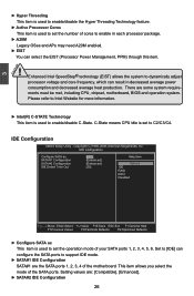
... item is used to enable/disable the Hyper Threading Technology feature. ► Active Processor Cores This item is used to set the number of the motherboard. Please refer to Intel Website for more information. ► Intel(R) C-STATE Technology This item is used to set to enable in each processor package. &#...: [Compatible], [Enhanced]. ► SATA#2 IDE Configuration 26 Copyright (C) 1985-2009, American Megatrends, Inc. Setting values are some system requirements must be met, including CPU, chipset, motherboard, BIOS and operation system. IDE Configuration CMOS Setup Utility -
... item is used to enable/disable the Hyper Threading Technology feature. ► Active Processor Cores This item is used to set the number of the motherboard. Please refer to Intel Website for more information. ► Intel(R) C-STATE Technology This item is used to set to enable in each processor package. &#...: [Compatible], [Enhanced]. ► SATA#2 IDE Configuration 26 Copyright (C) 1985-2009, American Megatrends, Inc. Setting values are some system requirements must be met, including CPU, chipset, motherboard, BIOS and operation system. IDE Configuration CMOS Setup Utility -


