User manual
Page 5
... CPU fan is not properly installed. ■ We cannot guarantee that your system can operate normally when your system. ! Incorrect connections might damage the motherboard. ■ When handling the motherboard, avoid touching any metal leads or connectors. ■ If there is a PCI Express x16 graphics card installed in your system, we recommend using a 24-pin ATX power supply to get the best performance. ■ Before turning on the overclocking...
... CPU fan is not properly installed. ■ We cannot guarantee that your system can operate normally when your system. ! Incorrect connections might damage the motherboard. ■ When handling the motherboard, avoid touching any metal leads or connectors. ■ If there is a PCI Express x16 graphics card installed in your system, we recommend using a 24-pin ATX power supply to get the best performance. ■ Before turning on the overclocking...
User manual
Page 6
... Introduction Product Specifications 2 Layout...4 Back Panel Connectors 5 Chapter 2 Hardware Install Install the CPU and CPU Cooler 8 Install the Memory 11 Install an Expansion Card 13 Install other Internal Connectors 14 Jumpers 17 Chapter 3 BIOS Setup .....E.n.t.er.B.I.O.S.S..et.u.p 20 Main...21 Advanced 23 Power Management 28 .....H.ea.lt.h...30 Chipset 31 Boot...32 Security 33 Save & Exit 34 Chapter 4 CD Instruction Install driver and utility 36 FOX ONE Main Page 39 CPU Control 43 Frequency Control 45 Limit Setting 46 Voltage Control 48 Fan Control 49 FOX...
... Introduction Product Specifications 2 Layout...4 Back Panel Connectors 5 Chapter 2 Hardware Install Install the CPU and CPU Cooler 8 Install the Memory 11 Install an Expansion Card 13 Install other Internal Connectors 14 Jumpers 17 Chapter 3 BIOS Setup .....E.n.t.er.B.I.O.S.S..et.u.p 20 Main...21 Advanced 23 Power Management 28 .....H.ea.lt.h...30 Chipset 31 Boot...32 Security 33 Save & Exit 34 Chapter 4 CD Instruction Install driver and utility 36 FOX ONE Main Page 39 CPU Control 43 Frequency Control 45 Limit Setting 46 Voltage Control 48 Fan Control 49 FOX...
User manual
Page 9
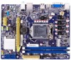
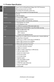
... Slots Storage LAN Audio USB Internal Connectors Support Intel Ivy Bridge/Sandy Bridge LGA 1155 Processors, Max processor power up to 95W For the latest CPU information, please visit: http://www.foxconnsupport.com/cpusupportlist.aspx Intel® H61 Intel® HD Graphics 2 x 240-pin DDR3 DIMMs Support up to 16GB of system memory Dual channel DDR3 1333/1066 MHz architecture 1 x PCI Express 3.0 x 16 slot 1 x PCI Express x1 slot 4 x SATA 2.0 connectors (3Gb/s data transfer rate) Realtek RTL8111F(H61MXE-V Use RTL8105E) Lan chip...
... Slots Storage LAN Audio USB Internal Connectors Support Intel Ivy Bridge/Sandy Bridge LGA 1155 Processors, Max processor power up to 95W For the latest CPU information, please visit: http://www.foxconnsupport.com/cpusupportlist.aspx Intel® H61 Intel® HD Graphics 2 x 240-pin DDR3 DIMMs Support up to 16GB of system memory Dual channel DDR3 1333/1066 MHz architecture 1 x PCI Express 3.0 x 16 slot 1 x PCI Express x1 slot 4 x SATA 2.0 connectors (3Gb/s data transfer rate) Realtek RTL8111F(H61MXE-V Use RTL8105E) Lan chip...
User manual
Page 13
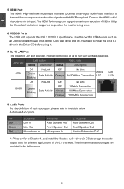
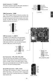
Connect the HDMI audio/ video device to this port for different applications of 2/4/5.1 channels. USB 3.0 Ports The USB port supports the USB 3.0/2.0/1.1 specification. RJ-45 LAN Port The Ethernet LAN port provides Internet connection at up to transmit the uncompressed audio/video signals and is HDCP compliant. You need to assign the audio output ports for USB devices such as an USB keyboard/mouse, USB printer, USB flash drive and etc. Left: Active LAN Type Status Description Status Right: Link Description Off No Link...
Connect the HDMI audio/ video device to this port for different applications of 2/4/5.1 channels. USB 3.0 Ports The USB port supports the USB 3.0/2.0/1.1 specification. RJ-45 LAN Port The Ethernet LAN port provides Internet connection at up to transmit the uncompressed audio/video signals and is HDCP compliant. You need to assign the audio output ports for USB devices such as an USB keyboard/mouse, USB printer, USB flash drive and etc. Left: Active LAN Type Status Description Status Right: Link Description Off No Link...
User manual
Page 14
...; Install the Memory ■ Install an Expansion Card ■ Install other Internal Connectors ■ Jumpers Please visit the following website for more supporting information about your motherboard. CPU Support List: http://www.foxconnsupport.com/cpusupportlist.aspx Memory, VGA Compatibility List: http://www.foxconnsupport.com/complist.aspx This chapter introduces the hardware installation process, including the installation of the CPU, memory, power supply, slots, pin headers and the mounting of these modules. Please refer to the motherboard layout prior...
...; Install the Memory ■ Install an Expansion Card ■ Install other Internal Connectors ■ Jumpers Please visit the following website for more supporting information about your motherboard. CPU Support List: http://www.foxconnsupport.com/cpusupportlist.aspx Memory, VGA Compatibility List: http://www.foxconnsupport.com/complist.aspx This chapter introduces the hardware installation process, including the installation of the CPU, memory, power supply, slots, pin headers and the mounting of these modules. Please refer to the motherboard layout prior...
User manual
Page 20
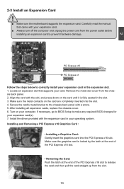
... chassis back panel. 2. Carefully read the manual that supports your expansion card. ■ Always turn off the computer and unplug the power cord from the power outlet before installing an expansion card to the chassis back panel with the expansion card in the slot. 3. After installing all expansion cards, replace the chassis cover. 6. Locate an expansion slot that came with your card. Installing and Removing a PCI Express x16 Graphics Card : • Installing a Graphics Card: Gently insert the graphics card into the slot. 4. Install the driver...
... chassis back panel. 2. Carefully read the manual that supports your expansion card. ■ Always turn off the computer and unplug the power cord from the power outlet before installing an expansion card to the chassis back panel with the expansion card in the slot. 3. After installing all expansion cards, replace the chassis cover. 6. Locate an expansion slot that came with your card. Installing and Removing a PCI Express x16 Graphics Card : • Installing a Graphics Card: Gently insert the graphics card into the slot. 4. Install the driver...
User manual
Page 22
... monitored in "Health" section of the BIOS Setup. These fans can be automatically turned off after the system enter S3, S4 and S5 sleeping states. D+ D+ GND GND EMPTY GND 9 10 F_USB1/2 Fan Connectors : CPU_FAN, SYS_FAN1 There are two main fan headers on its motherboard. Serial ATA II interface allows up to make transactions and communication more trustworthy. By connecting through USB cables with SATA Hard Disk or CD devices which support this motherboard. Audio Connector...
... monitored in "Health" section of the BIOS Setup. These fans can be automatically turned off after the system enter S3, S4 and S5 sleeping states. D+ D+ GND GND EMPTY GND 9 10 F_USB1/2 Fan Connectors : CPU_FAN, SYS_FAN1 There are two main fan headers on its motherboard. Serial ATA II interface allows up to make transactions and communication more trustworthy. By connecting through USB cables with SATA Hard Disk or CD devices which support this motherboard. Audio Connector...

User manual
Page 23
... into sleep mode (S1) , the LED is directional with COM1 connector in S3/ S4 sleep state or power off . Reset Switch (RESET-SW) Attach the connector to connect with +/- PWR-LED - This 2-pin connector is blinking; Speaker Connector : SPEAKER The speaker connector is on the chassis. 2 Front Panel Connector : FP1 This motherboard includes one serial RS232 COM port for connecting the front panel switch and LED Indicators. The system can be turned on the front panel of the hard disks. Hard Disk LED Connector (HDD-LED) Connect to a security switch on...
... into sleep mode (S1) , the LED is directional with COM1 connector in S3/ S4 sleep state or power off . Reset Switch (RESET-SW) Attach the connector to connect with +/- PWR-LED - This 2-pin connector is blinking; Speaker Connector : SPEAKER The speaker connector is on the chassis. 2 Front Panel Connector : FP1 This motherboard includes one serial RS232 COM port for connecting the front panel switch and LED Indicators. The system can be turned on the front panel of the hard disks. Hard Disk LED Connector (HDD-LED) Connect to a security switch on...
User manual
Page 24
... content carefully prior to modifying any jumper on the two pins to leave the Pins 1-2 open. 4. The shorting can be done by touching two pins by a screwdriver for a few second, remove the metal object to temporarily short them . Jumper Diagram Definition Description 1 1 1 Closed Open Set Pin 1 and Pin 2 closed Set Pin 1 and Pin 2 O�p�e�n� Clear CMOS Jumper: CLR_CMOS The motherboard uses CMOS RAM to store the basic hardware information...
... content carefully prior to modifying any jumper on the two pins to leave the Pins 1-2 open. 4. The shorting can be done by touching two pins by a screwdriver for a few second, remove the metal object to temporarily short them . Jumper Diagram Definition Description 1 1 1 Closed Open Set Pin 1 and Pin 2 closed Set Pin 1 and Pin 2 O�p�e�n� Clear CMOS Jumper: CLR_CMOS The motherboard uses CMOS RAM to store the basic hardware information...
User manual
Page 25
... This motherboard uses PCH_ME_ENABLE jumper to pins 2-3 first. 18 Before flashing BIOS ROM, you need to set PCH_ME_ENABLE jumper to enable or disable Intel® Management Engine function. Intel® Management Engine (ME) is an embedded microcontroller located in Intel chipset. It provides latest IT management features such as Intel® AMT, that allows to pins 2-3, you can disable the Intel® Management Engine function. 1 Enable 2 (Default) 3 1 Disable...
... This motherboard uses PCH_ME_ENABLE jumper to pins 2-3 first. 18 Before flashing BIOS ROM, you need to set PCH_ME_ENABLE jumper to enable or disable Intel® Management Engine function. Intel® Management Engine (ME) is an embedded microcontroller located in Intel chipset. It provides latest IT management features such as Intel® AMT, that allows to pins 2-3, you can disable the Intel® Management Engine function. 1 Enable 2 (Default) 3 1 Disable...
User manual
Page 27
... resulted from the change the default values in the BIOS Setup, and we shall not be changed through this menu to enter Setup. ! Boot Boot features can be set up through this menu. What you need now is explained below: Main It displays the basic system configuration, such as less I/O cards, less memory ...etc.), still, it may offer better performance in correct password before boot or access to maintain optimal...
... resulted from the change the default values in the BIOS Setup, and we shall not be changed through this menu to enter Setup. ! Boot Boot features can be set up through this menu. What you need now is explained below: Main It displays the basic system configuration, such as less I/O cards, less memory ...etc.), still, it may offer better performance in correct password before boot or access to maintain optimal...
User manual
Page 30
... running. 23 Main Advanced Chipset Boot Security Save & Exit ▶ S5 RTC Wake Settings ▶ CPU Configuration ▶ Performance Tuning ▶ IT8772E Super IO Configuration ▶ Onboard Device Configuration ▶ Power Management ▶ SATA Configuration ▶ Health System Super IO Chip Parameters. → ← : Select Screen ↑ ↓ : Select Item Enter: Select +/-: Change Opt. F1: General Help F2: Previous Values F3: Optimized Defaults F4: Save & Exit ESC: Exit Version 2.14...
... running. 23 Main Advanced Chipset Boot Security Save & Exit ▶ S5 RTC Wake Settings ▶ CPU Configuration ▶ Performance Tuning ▶ IT8772E Super IO Configuration ▶ Onboard Device Configuration ▶ Power Management ▶ SATA Configuration ▶ Health System Super IO Chip Parameters. → ← : Select Screen ↑ ↓ : Select Item Enter: Select +/-: Change Opt. F1: General Help F2: Previous Values F3: Optimized Defaults F4: Save & Exit ESC: Exit Version 2.14...
User manual
Page 31
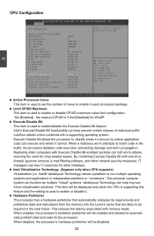
... item is used to enable or disable CPUID maximum value limit configuration. CPU Configuration Aptio Setup Utility - When disabled, the processor's hardware prefetcher will be displayed only when the CPU is supporting this feature and the setting is used to set the number of malicious buffer overflow attacks when combined with anti-virus, firewall, spyware removal, e-mail filtering software, and other initiatives. ► Intel Virtualization Technology (Appears only when CPU supports) Virtualization (i.e. F1...
... item is used to enable or disable CPUID maximum value limit configuration. CPU Configuration Aptio Setup Utility - When disabled, the processor's hardware prefetcher will be displayed only when the CPU is supporting this feature and the setting is used to set the number of malicious buffer overflow attacks when combined with anti-virus, firewall, spyware removal, e-mail filtering software, and other initiatives. ► Intel Virtualization Technology (Appears only when CPU supports) Virtualization (i.e. F1...
User manual
Page 32
... ▶ CPU Configuration ▶ North Bridge Configuration CPU Configuration 3 → ← : Select Screen ↑ ↓ : Select Item Enter: Select +/-: Change Opt. There are some system requirements must be met, including CPU, chipset, motherboard, BIOS and operation system. When enabled, the processor will only retrieve the currently requested cache line. F1: General Help F2: Previous Values F3: Optimized Defaults F4: Save & Exit ESC: Exit Version 2.14.1219...
... ▶ CPU Configuration ▶ North Bridge Configuration CPU Configuration 3 → ← : Select Screen ↑ ↓ : Select Item Enter: Select +/-: Change Opt. There are some system requirements must be met, including CPU, chipset, motherboard, BIOS and operation system. When enabled, the processor will only retrieve the currently requested cache line. F1: General Help F2: Previous Values F3: Optimized Defaults F4: Save & Exit ESC: Exit Version 2.14.1219...
User manual
Page 33
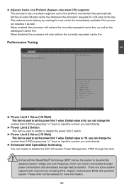
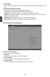
... marked frequency in specific condi- Options:[Automatic], [Manual], [XMP Profile 1], [XMP Profile 2]. [Automatic]- 3 ►Turbo Mode Turbo mode allows processor cores to run faster than its submenu. ► Serial Port This item is used to enable or disable the serial port. ► Device Settings This item shows the resource assigned to the serial port. ► Change Settings This item is used to select an optimal settings for the serial port. 26 IT8772E Super IO Configuration Aptio Setup Utility -
... marked frequency in specific condi- Options:[Automatic], [Manual], [XMP Profile 1], [XMP Profile 2]. [Automatic]- 3 ►Turbo Mode Turbo mode allows processor cores to run faster than its submenu. ► Serial Port This item is used to enable or disable the serial port. ► Device Settings This item shows the resource assigned to the serial port. ► Change Settings This item is used to select an optimal settings for the serial port. 26 IT8772E Super IO Configuration Aptio Setup Utility -
User manual
Page 34
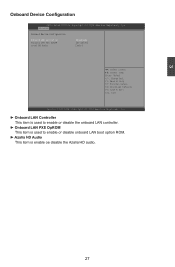
... Optimized Defaults F4: Save & Exit ESC: Exit Version 2.142.1219. 3 Onboard Device Configuration Aptio Setup Utility - Advanced Onboard Device Configuration Onboard LAN Controller [Enabled] Onboard LAN PXE OpROM [Disabled] intel HD Audio Auto] → ← : Select Screen ↑ ↓ : Select Item Enter: Select +/-: Change Opt. Copyright (C) 2010 American Megatrends, Inc. ► Onboard LAN Controller This item is used to enable or disable the onboard LAN controller. ► Onboard LAN PXE OpROM This item is used to enable or disable onboard LAN boot option ROM...
... Optimized Defaults F4: Save & Exit ESC: Exit Version 2.142.1219. 3 Onboard Device Configuration Aptio Setup Utility - Advanced Onboard Device Configuration Onboard LAN Controller [Enabled] Onboard LAN PXE OpROM [Disabled] intel HD Audio Auto] → ← : Select Screen ↑ ↓ : Select Item Enter: Select +/-: Change Opt. Copyright (C) 2010 American Megatrends, Inc. ► Onboard LAN Controller This item is used to enable or disable the onboard LAN controller. ► Onboard LAN PXE OpROM This item is used to enable or disable onboard LAN boot option ROM...
User manual
Page 35
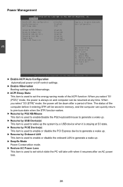
... PS2 KB/Mouse Resume By Onboard LAN Resume By USB Device(s) Resume By PCIE PME DeepSx Mode Restore AC Power Loss [Enabled] [Disabled] [Enabled] [Disabled] [Disabled] [Last State] → ← : Select Screen ↑ ↓ : Select Item Enter: Select +/-: Change Opt. C opyright (C) 2011 American Megatrends, Inc A d v anced Enable ACPI Auto Configuration [Disabled] Enable Hibernation [Enabled] ACPI Sleep State [S3] Enables or Disables BIOS ACPI Auto Configuration. F1: General Help F2: Previous Values F3: Optimized Defaults F4: Save & Exit ESC: Exit Version 2.14.1219.
... PS2 KB/Mouse Resume By Onboard LAN Resume By USB Device(s) Resume By PCIE PME DeepSx Mode Restore AC Power Loss [Enabled] [Disabled] [Enabled] [Disabled] [Disabled] [Last State] → ← : Select Screen ↑ ↓ : Select Item Enter: Select +/-: Change Opt. C opyright (C) 2011 American Megatrends, Inc A d v anced Enable ACPI Auto Configuration [Disabled] Enable Hibernation [Enabled] ACPI Sleep State [S3] Enables or Disables BIOS ACPI Auto Configuration. F1: General Help F2: Previous Values F3: Optimized Defaults F4: Save & Exit ESC: Exit Version 2.14.1219.
User manual
Page 36
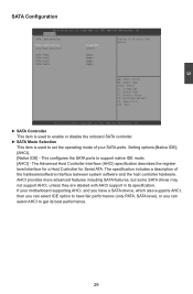
3 SATA Configuration Aptio Setup Utility - Setting options:[Native IDE]; [AHCI]. [Native IDE] - The Advanced Host Controller Interface (AHCI) specification describes the register level interface for a Host Controller for Serial ATA. If your SATA ports. Advanced SATA Configuration SATA Controller(s) SATA Mode Selection [Enabled] [AHCI] Enables or Disables SATA Device. AHCI provides more advanced features including SATA features, but some SATA drives may not support AHCI, unless they are labeled with AHCI support in its best performance. 29 This configures the SATA ports to...
3 SATA Configuration Aptio Setup Utility - Setting options:[Native IDE]; [AHCI]. [Native IDE] - The Advanced Host Controller Interface (AHCI) specification describes the register level interface for a Host Controller for Serial ATA. If your SATA ports. Advanced SATA Configuration SATA Controller(s) SATA Mode Selection [Enabled] [AHCI] Enables or Disables SATA Device. AHCI provides more advanced features including SATA features, but some SATA drives may not support AHCI, unless they are labeled with AHCI support in its best performance. 29 This configures the SATA ports to...
User manual
Page 39
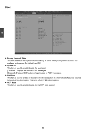
... active boot option. Copyright (C) 2010 American Megatrends, Inc. ► Bootup Numlock State This item defines if the keyboard Num Lock key is active when your system is used to enable/disable the quiet boot. [Disabled] : Displays the normal POST messages. [Enabled] : Displays OEM customer logo instead of devices required to enable/disable device UEFI boot support. 32 The available settings are: On (default) and Off. ► Quiet Boot This item is started. 3 Boot Aptio Setup Utility - Main Advanced Chipset...
... active boot option. Copyright (C) 2010 American Megatrends, Inc. ► Bootup Numlock State This item defines if the keyboard Num Lock key is active when your system is used to enable/disable the quiet boot. [Disabled] : Displays the normal POST messages. [Enabled] : Displays OEM customer logo instead of devices required to enable/disable device UEFI boot support. 32 The available settings are: On (default) and Off. ► Quiet Boot This item is started. 3 Boot Aptio Setup Utility - Main Advanced Chipset...
User manual
Page 43
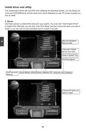
Driver Use these options to install all the drivers for your PC screen to guide you want to install, or you can simply put it manually. 4 Install driver and utility This motherboard comes with one DVD, after installing the Operating System, you can click on each individual driver to install it into your DVD-ROM drive, and the main menu will be displayed on your system. Manual Installation Step by Step Automatic Installation by One Click Drop...
Driver Use these options to install all the drivers for your PC screen to guide you want to install, or you can simply put it manually. 4 Install driver and utility This motherboard comes with one DVD, after installing the Operating System, you can click on each individual driver to install it into your DVD-ROM drive, and the main menu will be displayed on your system. Manual Installation Step by Step Automatic Installation by One Click Drop...


