User manual
Page 1
H61AP Series Motherboard User's Manual
H61AP Series Motherboard User's Manual
User manual
Page 2
... for the environment and human health, which could otherwise be changed or modified at any time, Foxconn does not obligate itself to the physical motherboard for H61AP-S/H61AP motherboard. For more information about recycling of this product, please contact your local city office, your household...Version: User's Manual V1.2 for specific features. WEEE: The use motherboard better, and tells you will help you to use of this symbol indicates that this product is the intellectual property of Foxconn, Inc. More information: If you want more detailed information about ...
... for the environment and human health, which could otherwise be changed or modified at any time, Foxconn does not obligate itself to the physical motherboard for H61AP-S/H61AP motherboard. For more information about recycling of this product, please contact your local city office, your household...Version: User's Manual V1.2 for specific features. WEEE: The use motherboard better, and tells you will help you to use of this symbol indicates that this product is the intellectual property of Foxconn, Inc. More information: If you want more detailed information about ...
User manual
Page 3
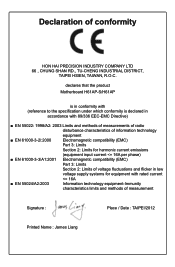
... information technology equipment ■ EN 61000-3-2/:2000 Electromagnetic compatibility (EMC) Part 3: Limits Section 2: Limits for harmonic current emissions (equipment input current declares that the product Motherboard H61AP-S/H61AP is in conformity with (reference to the specification under which conformity is declared in accordance with 89/336 EEC-EMC Directive) ■ EN 55022: 1998...
... information technology equipment ■ EN 61000-3-2/:2000 Electromagnetic compatibility (EMC) Part 3: Limits Section 2: Limits for harmonic current emissions (equipment input current declares that the product Motherboard H61AP-S/H61AP is in conformity with (reference to the specification under which conformity is declared in accordance with 89/336 EEC-EMC Directive) ■ EN 55022: 1998...
User manual
Page 4
... the FCC Rules. Declaration of conformity Trade Name: Model Name: Responsible Party: Address: Telephone: Facsimile: FOXCONN H61AP-S/H61AP PCE Industry Inc. 458 E. Operation is subject to comply with Part 15 of Product: Manufacturer: Address: FCC Class B Subassembly Motherboard HON HAI PRECISION INDUSTRY COMPANY LTD 66 , CHUNG SHAN RD., TU-CHENG INDUSTRIAL DISTRICT, TAIPEI HSIEN...
... the FCC Rules. Declaration of conformity Trade Name: Model Name: Responsible Party: Address: Telephone: Facsimile: FOXCONN H61AP-S/H61AP PCE Industry Inc. 458 E. Operation is subject to comply with Part 15 of Product: Manufacturer: Address: FCC Class B Subassembly Motherboard HON HAI PRECISION INDUSTRY COMPANY LTD 66 , CHUNG SHAN RD., TU-CHENG INDUSTRIAL DISTRICT, TAIPEI HSIEN...
User manual
Page 5
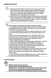
...which will quickly damage your computer : ■ It is suggested to select high-quality, certified fans in order to avoid damage to the motherboard and CPU due to the use of your system. Also, make sure there are no leftover screws or metal components placed on the overclocking ...to unplug the power supply cord may result in serious damage to come in your CPU is overclocked. Incorrect connections might damage the motherboard. ■ When handling the motherboard, avoid touching any , when connecting USB, audio, 1394a, RS232 COM, IrDA or S/PDIF cables to unplug the AC power cord...
...which will quickly damage your computer : ■ It is suggested to select high-quality, certified fans in order to avoid damage to the motherboard and CPU due to the use of your system. Also, make sure there are no leftover screws or metal components placed on the overclocking ...to unplug the power supply cord may result in serious damage to come in your CPU is overclocked. Incorrect connections might damage the motherboard. ■ When handling the motherboard, avoid touching any , when connecting USB, audio, 1394a, RS232 COM, IrDA or S/PDIF cables to unplug the AC power cord...

User manual
Page 8
Foxconn products are engineered to maximize computing power, providing only what you for break-through performance. This chapter includes the following information: ■ Product Specifications ■ Layout ■ Back Panel Connectors Chapter 1 Product Introduction Thank you need for buying Foxconn H61AP Series motherboard.
Foxconn products are engineered to maximize computing power, providing only what you for break-through performance. This chapter includes the following information: ■ Product Specifications ■ Layout ■ Back Panel Connectors Chapter 1 Product Introduction Thank you need for buying Foxconn H61AP Series motherboard.
User manual
Page 11
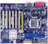
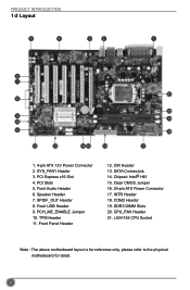
... USB Header 9. CIR Header 13. PCI Express x16 Slot 4. Clear CMOS Jumper 16. 24-pin ATX Power Connector 17. LGA1155 CPU Socket Note : The above motherboard layout is for reference only, please refer to the physical...
... USB Header 9. CIR Header 13. PCI Express x16 Slot 4. Clear CMOS Jumper 16. 24-pin ATX Power Connector 17. LGA1155 CPU Socket Note : The above motherboard layout is for reference only, please refer to the physical...
User manual
Page 14
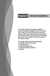
This chapter includes the following information : ■ Install the CPU and CPU Cooler ■ Install the Memory ■ Install an Expansion Card ■ Install other Internal Connectors ■ Jumpers Chapter 2 Hardware Installation This chapter introduces the hardware installation process, including the installation of the CPU, memory, power supply, slots, pin headers and the mounting of these modules. Caution should be exercised during the installation of jumpers. Please refer to the motherboard layout prior to any installation and read the contents in this chapter carefully.
This chapter includes the following information : ■ Install the CPU and CPU Cooler ■ Install the Memory ■ Install an Expansion Card ■ Install other Internal Connectors ■ Jumpers Chapter 2 Hardware Installation This chapter introduces the hardware installation process, including the installation of the CPU, memory, power supply, slots, pin headers and the mounting of these modules. Caution should be exercised during the installation of jumpers. Please refer to the motherboard layout prior to any installation and read the contents in this chapter carefully.
User manual
Page 15
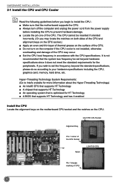
... supports HT Technology ■ A chipset that supports HT Technology ■ An operating system that is optimized for HT Technology ■ A BIOS that the motherboard supports the CPU. ■ Always turn on the computer if the CPU cooler is not recommended that the system bus frequency be inserted if oriented...of CPU 8 The CPU cannot be set the frequency beyond hardware specifications since it enabled Install the CPU Locate the alignment keys on the motherboard CPU socket and the notches on the surface of the CPU. ■ Do not turn off the computer and unplug the power cord ...
... supports HT Technology ■ A chipset that supports HT Technology ■ An operating system that is optimized for HT Technology ■ A BIOS that the motherboard supports the CPU. ■ Always turn on the computer if the CPU cooler is not recommended that the system bus frequency be inserted if oriented...of CPU 8 The CPU cannot be set the frequency beyond hardware specifications since it enabled Install the CPU Locate the alignment keys on the motherboard CPU socket and the notches on the surface of the CPU. ■ Do not turn off the computer and unplug the power cord ...
User manual
Page 17
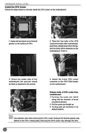
...bolts will be fixed as depicted in the picture. 3 2 1 4. Turning push pin clockwise to correctly install the CPU cooler on the motherboard. Use extreme care when removing the CPU cooler because the thermal grease may damage the CPU. 10 Attach the 4-wire CPU cooler connector to ... header on the surface of the motherboard, push them straight down from motherboard : 1.Turning the push pin (bolt) along with the direction of the motherboard, the push pin should be fastened on the motherboard. 1. Apply and spread an even thermal grease on the motherboard . Place the four bolts of ...
...bolts will be fixed as depicted in the picture. 3 2 1 4. Turning push pin clockwise to correctly install the CPU cooler on the motherboard. Use extreme care when removing the CPU cooler because the thermal grease may damage the CPU. 10 Attach the 4-wire CPU cooler connector to ... header on the surface of the motherboard, push them straight down from motherboard : 1.Turning the push pin (bolt) along with the direction of the motherboard, the push pin should be fastened on the motherboard. 1. Apply and spread an even thermal grease on the motherboard . Place the four bolts of ...
User manual
Page 18
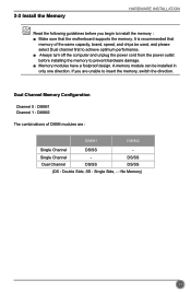
It is recommended that the motherboard supports the memory. Single Channel Dual Channel DS/SS DS/SS DS/SS (DS : Double Side, SS : Single Side, - : No Memory) 11 A memory module can ...
It is recommended that the motherboard supports the memory. Single Channel Dual Channel DS/SS DS/SS DS/SS (DS : Double Side, SS : Single Side, - : No Memory) 11 A memory module can ...
User manual
Page 20
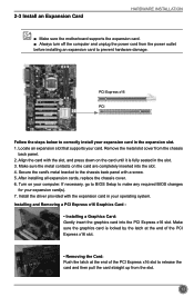
... with the slot, and press down on your computer. Install the driver provided with a screw. 5. 2-3 Install an Expansion Card HARDWARE INSTALLATION ■ Make sure the motherboard supports the expansion card. ■ Always turn off the computer and unplug the power cord from the power outlet before installing an expansion card to...
... with the slot, and press down on your computer. Install the driver provided with a screw. 5. 2-3 Install an Expansion Card HARDWARE INSTALLATION ■ Make sure the motherboard supports the expansion card. ■ Always turn off the computer and unplug the power cord from the power outlet before installing an expansion card to...
User manual
Page 21
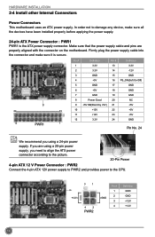
... 3.3V 24 GND 12 PWR1 1 Pin No. 24 We recommend you using a 20-pin power supply, you are properly aligned with the connector on the motherboard. HARDWARE INSTALLATION 2-4 Install other Internal Connectors Power Connectors This...
... 3.3V 24 GND 12 PWR1 1 Pin No. 24 We recommend you using a 20-pin power supply, you are properly aligned with the connector on the motherboard. HARDWARE INSTALLATION 2-4 Install other Internal Connectors Power Connectors This...
User manual
Page 22
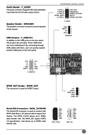
... choice. By connecting through USB cables with SATA Hard Disk or CD devices which support this product also provides 10-pin USB headers on its motherboard. D- Audio Header : F_AUDIO The audio connector supports HD Audio standard. Speaker Header : SPEAKER The speaker connector is used to 6GB/s data transfer rate. 1 GND TX...
... choice. By connecting through USB cables with SATA Hard Disk or CD devices which support this product also provides 10-pin USB headers on its motherboard. D- Audio Header : F_AUDIO The audio connector supports HD Audio standard. Speaker Header : SPEAKER The speaker connector is used to 6GB/s data transfer rate. 1 GND TX...
User manual
Page 23
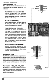
HARDWARE INSTALLATION Front Panel Header : FP1 This motherboard includes one connector for connecting the front panel switch and LED Indicators. sign. This 2-pin connector is directional with +/- Push this function, you should purchase ...
HARDWARE INSTALLATION Front Panel Header : FP1 This motherboard includes one connector for connecting the front panel switch and LED Indicators. sign. This 2-pin connector is directional with +/- Push this function, you should purchase ...
User manual
Page 24
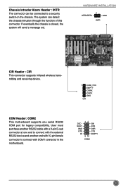
... is closed, the system will send a message out. User must purchase another end with 10-pin female connector to connect with COM1 connector in the motherboard. Chassis Intruder Alarm Header : INTR The connector can detect the chassis intrusion through the function of this connector. HARDWARE INSTALLATION INTRUDERJ 1 GND INTR CIR Header... : CIR This connector supports infrared wireless transmitting and receiving device. 1 5VSB_SYS EMPTY CIRRX CIRTX GND CIR COM Header: COM2 This motherboard supports one end to a security switch on the chassis.
... is closed, the system will send a message out. User must purchase another end with 10-pin female connector to connect with COM1 connector in the motherboard. Chassis Intruder Alarm Header : INTR The connector can detect the chassis intrusion through the function of this connector. HARDWARE INSTALLATION INTRUDERJ 1 GND INTR CIR Header... : CIR This connector supports infrared wireless transmitting and receiving device. 1 5VSB_SYS EMPTY CIRRX CIRTX GND CIR COM Header: COM2 This motherboard supports one end to a security switch on the chassis.
User manual
Page 25
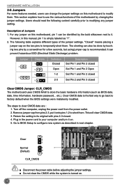
... carefully prior to modifying any jumper on the two pins to short them . Plug in this motherboard by a screwdriver for a few seconds, but using jumper cap is turned on this motherboard, pin 1 can be done by touching two pins by changing the jumper settings. Description of ... store the basic hardware information (such as "1". 2. Return the setting to its original with pins 2-3 closed Clear CMOS Jumper: CLR_CMOS The motherboard uses CMOS RAM to factory default when the BIOS settings were mistakenly modified. Remove jumper cap from the power outlet. 2. This section explains...
... carefully prior to modifying any jumper on the two pins to short them . Plug in this motherboard by a screwdriver for a few seconds, but using jumper cap is turned on this motherboard, pin 1 can be done by touching two pins by changing the jumper settings. Description of ... store the basic hardware information (such as "1". 2. Return the setting to its original with pins 2-3 closed Clear CMOS Jumper: CLR_CMOS The motherboard uses CMOS RAM to factory default when the BIOS settings were mistakenly modified. Remove jumper cap from the power outlet. 2. This section explains...
User manual
Page 26
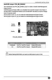
...® Management Engine function. Intel® Management Engine (ME) is an embedded microcontroller located in Intel chipset. Intel® ME Jumper: PCH_ME_ENABLE HARDWARE INSTALLATION This motherboard uses PCH_ME_ENABLE jumper to pins 2-3 first. 19
...® Management Engine function. Intel® Management Engine (ME) is an embedded microcontroller located in Intel chipset. Intel® ME Jumper: PCH_ME_ENABLE HARDWARE INSTALLATION This motherboard uses PCH_ME_ENABLE jumper to pins 2-3 first. 19
User manual
Page 32
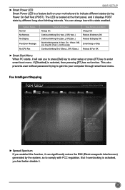
... blinking On (2sec.), Off (2sec.) Quick blinking twice (1/3sec. On, 1/3sec. BIOS SETUP ► Smart Power LED Smart Power LED is a feature built on your motherboard to get into your computer through smart boot menu. Continue blinking On (1/2sec.), Off (1/2sec.) Stop Blinking Condition Always On Reboot & Memory OK Reboot & Display...
... blinking On (2sec.), Off (2sec.) Quick blinking twice (1/3sec. On, 1/3sec. BIOS SETUP ► Smart Power LED Smart Power LED is a feature built on your motherboard to get into your computer through smart boot menu. Continue blinking On (1/2sec.), Off (1/2sec.) Stop Blinking Condition Always On Reboot & Memory OK Reboot & Display...
User manual
Page 34
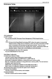
...; ←: Select Screen ↑ ↓/Click: Select Item Enter/Dbl Click: Select +/-: Change Opt. There are some system requirements must be met, including CPU, chipset, motherboard, BIOS and operation system. Options: [Automatic], [Manual], [XMP Profile 1], [XMP Profile 2]. [Automatic]- The following items appear only when the option is set to "Manual". ►...
...; ←: Select Screen ↑ ↓/Click: Select Item Enter/Dbl Click: Select +/-: Change Opt. There are some system requirements must be met, including CPU, chipset, motherboard, BIOS and operation system. Options: [Automatic], [Manual], [XMP Profile 1], [XMP Profile 2]. [Automatic]- The following items appear only when the option is set to "Manual". ►...


