User manual
Page 5
.... ■ Before turning on the motherboard. It is recommended to high temperature. Also, make sure there are no leftover screws or metal components placed on the motherboard or within the computer casing. ■ If you are uncertain about any metal leads or connectors. ■ If there is a PCI Express x16 graphics card installed in your system, we recommend using a 24-pin ATX power supply to come in...
.... ■ Before turning on the motherboard. It is recommended to high temperature. Also, make sure there are no leftover screws or metal components placed on the motherboard or within the computer casing. ■ If you are uncertain about any metal leads or connectors. ■ If there is a PCI Express x16 graphics card installed in your system, we recommend using a 24-pin ATX power supply to come in...
User manual
Page 6
... Specifications 2 1-2 Layout...4 1-3 Back Panel Connectors 5 Chapter 2 Hardware Installation 2-1 Install the CPU and CPU Cooler 8 Install the CPU 8 Install the CPU Cooler 10 2-2 Install the Memory 11 Dual Channel Memory Configuration 11 Installing a Memory 12 2-3 Install an Expansion Card 13 2-4 Install other Internal Connectors 14 2-5 Jumpers 18 Chapter 3 BIOS Setup Enter BIOS Setup 21 Main...22 F-center...24 Smart BIOS 24 Fox Intelligent Stepping 25 CPU Configuration 26 Performance Tuning 27 Advanced...29 North Bridge 29 ME Subsystem 30 Onboard Device Configuration 31 SATA...
... Specifications 2 1-2 Layout...4 1-3 Back Panel Connectors 5 Chapter 2 Hardware Installation 2-1 Install the CPU and CPU Cooler 8 Install the CPU 8 Install the CPU Cooler 10 2-2 Install the Memory 11 Dual Channel Memory Configuration 11 Installing a Memory 12 2-3 Install an Expansion Card 13 2-4 Install other Internal Connectors 14 2-5 Jumpers 18 Chapter 3 BIOS Setup Enter BIOS Setup 21 Main...22 F-center...24 Smart BIOS 24 Fox Intelligent Stepping 25 CPU Configuration 26 Performance Tuning 27 Advanced...29 North Bridge 29 ME Subsystem 30 Onboard Device Configuration 31 SATA...
User manual
Page 14
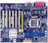
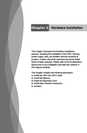
Caution should be exercised during the installation of jumpers. This chapter includes the following information : ■ Install the CPU and CPU Cooler ■ Install the Memory ■ Install an Expansion Card ■ Install other Internal Connectors ■ Jumpers Please refer to the motherboard layout prior to any installation and read the contents in this chapter carefully. Chapter 2 Hardware Installation This chapter introduces the hardware installation process, including the installation of the CPU, memory, power supply, slots, pin headers and the mounting of these modules.
Caution should be exercised during the installation of jumpers. This chapter includes the following information : ■ Install the CPU and CPU Cooler ■ Install the Memory ■ Install an Expansion Card ■ Install other Internal Connectors ■ Jumpers Please refer to the motherboard layout prior to any installation and read the contents in this chapter carefully. Chapter 2 Hardware Installation This chapter introduces the hardware installation process, including the installation of the CPU, memory, power supply, slots, pin headers and the mounting of these modules.
User manual
Page 20
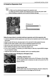
... card(s). 7. Installing and Removing a PCI Express x16 Graphics Card : • Installing a Graphics Card: Gently insert the graphics card into the slot. 4. If necessary, go to BIOS Setup to correctly install your expansion card in the slot. 3. 2-3 Install an Expansion Card HARDWARE INSTALLATION ■ Make sure the motherboard supports the expansion card. ■ Always turn off the computer and unplug the power cord from the power outlet before installing an expansion card to the chassis back panel with a screw. 5. After installing all expansion cards, replace...
... card(s). 7. Installing and Removing a PCI Express x16 Graphics Card : • Installing a Graphics Card: Gently insert the graphics card into the slot. 4. If necessary, go to BIOS Setup to correctly install your expansion card in the slot. 3. 2-3 Install an Expansion Card HARDWARE INSTALLATION ■ Make sure the motherboard supports the expansion card. ■ Always turn off the computer and unplug the power cord from the power outlet before installing an expansion card to the chassis back panel with a screw. 5. After installing all expansion cards, replace...
User manual
Page 23
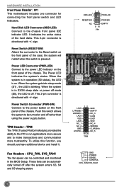
... chassis front panel IDE indicator LED. Hard Disk LED Connector (HDD-LED) Connect to the Reset switch on and off rather than using the power supply button. Power Switch Connector (PWR-SW) Connect to be controlled and monitored in operation (S0 status), the LED is directional with +/- The Power LED indicates the system's status. When the system gets into sleep mode (S1) , the LED is pressed. Push this function, you should purchase additional device and install it. HARDWARE INSTALLATION Front Panel Header : FP1 This motherboard...
... chassis front panel IDE indicator LED. Hard Disk LED Connector (HDD-LED) Connect to the Reset switch on and off rather than using the power supply button. Power Switch Connector (PWR-SW) Connect to be controlled and monitored in operation (S0 status), the LED is directional with +/- The Power LED indicates the system's status. When the system gets into sleep mode (S1) , the LED is pressed. Push this function, you should purchase additional device and install it. HARDWARE INSTALLATION Front Panel Header : FP1 This motherboard...
User manual
Page 25
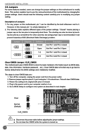
... BIOS data, date, time information, hardware password... The following content carefully prior to modifying any jumper on the two pins to temporarily short them. Turn off the computer, unplug the power cord from pins 2-3, put it on . 18 Go to BIOS Setup to configure new system as described in this manual, pin 1 is turned on . 5. HARDWARE INSTALLATION 2-5 Jumpers For some features needed, users can change the jumper settings on this motherboard...
... BIOS data, date, time information, hardware password... The following content carefully prior to modifying any jumper on the two pins to temporarily short them. Turn off the computer, unplug the power cord from pins 2-3, put it on . 18 Go to BIOS Setup to configure new system as described in this manual, pin 1 is turned on . 5. HARDWARE INSTALLATION 2-5 Jumpers For some features needed, users can change the jumper settings on this motherboard...
User manual
Page 26
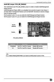
... Intel chipset. It provides latest IT management features such as Intel® AMT, that allows to enable or disable Intel® Management Engine function. Set the jumper to pins 1-2, you need to set ME jumper to pins 2-3, you can disable the Intel® Management Engine function. 1 Enable 2 (Default) 3 1 2 Disable 3 PCH_ME_ENABLE Definition 1-2(default) 2-3 Description Set Pin 1 and Pin 2 closed Set Pin 2 and Pin 3 closed Function Enable ME function Disable ME function CAUTION Before flashing BIOS ROM...
... Intel chipset. It provides latest IT management features such as Intel® AMT, that allows to enable or disable Intel® Management Engine function. Set the jumper to pins 1-2, you need to set ME jumper to pins 2-3, you can disable the Intel® Management Engine function. 1 Enable 2 (Default) 3 1 2 Disable 3 PCH_ME_ENABLE Definition 1-2(default) 2-3 Description Set Pin 1 and Pin 2 closed Set Pin 2 and Pin 3 closed Function Enable ME function Disable ME function CAUTION Before flashing BIOS ROM...
User manual
Page 28
... (such as CPU Name, memory size, system date, time and so on the computer, when the message "Press to enter Setup, to Boot Menu" appears at the bottom of your system loading is explained below: Main It displays the basic system configuration, such as less I /O cards installed. However, it may sometimes come out an unstable system. Security The Administrator/User password can be set up through...
... (such as CPU Name, memory size, system date, time and so on the computer, when the message "Press to enter Setup, to Boot Menu" appears at the bottom of your system loading is explained below: Main It displays the basic system configuration, such as less I /O cards installed. However, it may sometimes come out an unstable system. Security The Administrator/User password can be set up through...
User manual
Page 31
Smart BIOS Main F-center Advanced Boot Smart BIOS Power Health Smart Power LED Smart Boot Menu [Disabled] [Enabled] Security Save&Exit Smart Power LED Settings 24 → ←: Select Screen ↑ ↓/Click: Select Item Enter/Dbl Click: Select +/-: Change Opt. F1: General Help F2: Previous Values F3: Optimized Defaults F4: Save & Exit ESC/Right Click: Exit Version 2.14.1219. BIOS SETUP F-center Main F-center Advanced Boot Fox Control Center Super BIOS Protect ▶ Smart BIOS ▶ Fox Intelligent Stepping ▶ CPU Configuration ▶ ...
Smart BIOS Main F-center Advanced Boot Smart BIOS Power Health Smart Power LED Smart Boot Menu [Disabled] [Enabled] Security Save&Exit Smart Power LED Settings 24 → ←: Select Screen ↑ ↓/Click: Select Item Enter/Dbl Click: Select +/-: Change Opt. F1: General Help F2: Previous Values F3: Optimized Defaults F4: Save & Exit ESC/Right Click: Exit Version 2.14.1219. BIOS SETUP F-center Main F-center Advanced Boot Fox Control Center Super BIOS Protect ▶ Smart BIOS ▶ Fox Intelligent Stepping ▶ CPU Configuration ▶ ...
User manual
Page 32
... Reboot & Memory OK Reboot & Display OK Enter Setup or Skip Reboot & Fan OK ► Smart Boot Menu When PC starts, it . 25 But if overclocking is activated, you had better disable it will ask you enabled this state enabled. F1: General Help F2: Previous Values F3: Optimized Defaults F4: Save & Exit ESC/Right Click: Exit Version 2.14.1219. The LED is located at the front panel, and it...
... Reboot & Memory OK Reboot & Display OK Enter Setup or Skip Reboot & Fan OK ► Smart Boot Menu When PC starts, it . 25 But if overclocking is activated, you had better disable it will ask you enabled this state enabled. F1: General Help F2: Previous Values F3: Optimized Defaults F4: Save & Exit ESC/Right Click: Exit Version 2.14.1219. The LED is located at the front panel, and it...
User manual
Page 33
... disable CPU C6 (ACPI C3) report to OS. 26 Set Limit CPUID Maximum to run multiple operating systems and applications in independent partitions or "containers." This item will be [Disabled] for WinXP. ► Intel Virtualization Technology (Appears only when CPU supports) Virtualization (i.e. BIOS SETUP CPU Configuration Main F-center Advanced Boot CPU Configuration CPU Brand Name: Genuine Intel(R) CPU @ 2.20GHz L1 Data Cache L1 Code Cache L2 Cache L3 Cache Processor Stepping Max CPU Speed Min CPU Speed CPU Speed Processor Cores...
... disable CPU C6 (ACPI C3) report to OS. 26 Set Limit CPUID Maximum to run multiple operating systems and applications in independent partitions or "containers." This item will be [Disabled] for WinXP. ► Intel Virtualization Technology (Appears only when CPU supports) Virtualization (i.e. BIOS SETUP CPU Configuration Main F-center Advanced Boot CPU Configuration CPU Brand Name: Genuine Intel(R) CPU @ 2.20GHz L1 Data Cache L1 Code Cache L2 Cache L3 Cache Processor Stepping Max CPU Speed Min CPU Speed CPU Speed Processor Cores...
User manual
Page 34
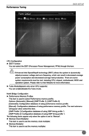
...: Exit Version 2.14.1219. CPU Configuration ► EIST Function You can enable/disable the Turbo mode. Please refer to set the memory multiplier. 27 North Bridge Configuration ► Performance Memory Profiles This item is used to set the memory clock multiplier. ► Memory Multiplier This item is used to Intel Website for more information. ► Turbo Mode(Appears only when CPU supports) You can select the EIST (Processor Power Management, PPM...
...: Exit Version 2.14.1219. CPU Configuration ► EIST Function You can enable/disable the Turbo mode. Please refer to set the memory multiplier. 27 North Bridge Configuration ► Performance Memory Profiles This item is used to set the memory clock multiplier. ► Memory Multiplier This item is used to Intel Website for more information. ► Turbo Mode(Appears only when CPU supports) You can select the EIST (Processor Power Management, PPM...
User manual
Page 37
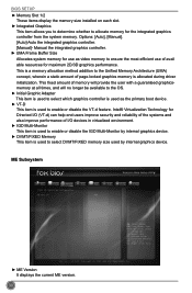
.../FIXED memory size used to allocate memory for use as the primary boot device. ► VT-D This item is allocated during driver initialization. Manual the integrated graphics controller. ► UMA Frame Buffer Size Allocates system memory for the integrated graphics controller from the system memory. ME Subsystem Main F-center Advanced Boot Intel ME Subsystem Configuration ME Version Power N/A Health Security Save&Exit → ←: Select Screen ↑ ↓/Click: Select Item Enter/Dbl...
.../FIXED memory size used to allocate memory for use as the primary boot device. ► VT-D This item is allocated during driver initialization. Manual the integrated graphics controller. ► UMA Frame Buffer Size Allocates system memory for the integrated graphics controller from the system memory. ME Subsystem Main F-center Advanced Boot Intel ME Subsystem Configuration ME Version Power N/A Health Security Save&Exit → ←: Select Screen ↑ ↓/Click: Select Item Enter/Dbl...
User manual
Page 38
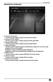
...item is used to enable the support for USB devices on legacy OS. F1: General Help F2: Previous Values F3: Optimized Defaults F4: Save & Exit ESC/Right Click: Exit Version 2.14.1219. Onboard Device Configuration BIOS SETUP Main F-center Advanced Boot Power Health Security Save&Exit Onboard Device Configuration Onboard LAN Controller Onboard LAN PXE OpROM Onboard USB Controller Legacy USB Support USB3.0 Support SATA3.0 Controller Azalia HD Audio Controller [Enabled] [Enabled] [Enabled] [Enabled] [Enabled] [Enabled] [Enabled] Onboard LAN Controller → ←: Select Screen...
...item is used to enable the support for USB devices on legacy OS. F1: General Help F2: Previous Values F3: Optimized Defaults F4: Save & Exit ESC/Right Click: Exit Version 2.14.1219. Onboard Device Configuration BIOS SETUP Main F-center Advanced Boot Power Health Security Save&Exit Onboard Device Configuration Onboard LAN Controller Onboard LAN PXE OpROM Onboard USB Controller Legacy USB Support USB3.0 Support SATA3.0 Controller Azalia HD Audio Controller [Enabled] [Enabled] [Enabled] [Enabled] [Enabled] [Enabled] [Enabled] Onboard LAN Controller → ←: Select Screen...
User manual
Page 39
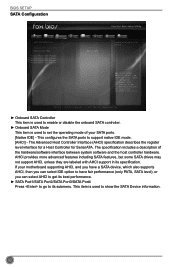
... motherboard supporting AHCI, and you have a SATA device, which also supports AHCI, then you can select IDE option to have fair performance (only PATA, SATA level), or you can select AHCI to get its specification. BIOS SETUP SATA Configuration Main F-center Advanced Boot Power Health Security Save&Exit SATA Configuration Onboard SATA Controller Onboard SATA Mode ▶ SATA Port1: Not Present ▶ SATA Port2: Not Present ▶ SATA Port3: Not Present ▶ SATA Port4: Not Present [Enabled] [Native IDE] Enable or disable SATA Device → ←: Select Screen...
... motherboard supporting AHCI, and you have a SATA device, which also supports AHCI, then you can select IDE option to have fair performance (only PATA, SATA level), or you can select AHCI to get its specification. BIOS SETUP SATA Configuration Main F-center Advanced Boot Power Health Security Save&Exit SATA Configuration Onboard SATA Controller Onboard SATA Mode ▶ SATA Port1: Not Present ▶ SATA Port2: Not Present ▶ SATA Port3: Not Present ▶ SATA Port4: Not Present [Enabled] [Native IDE] Enable or disable SATA Device → ←: Select Screen...
User manual
Page 40
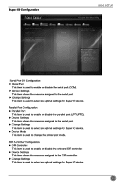
Super IO Configuration BIOS SETUP Main F-center Advanced Boot Power Health Security Save&Exit Super IO Configuration Super IO Chip IT8728 Set Parameters of Serial Port 1 (COMB) ▶ Serial Port 0 Configuration ▶ Serial Port 1 Configuration ▶ Parallel Port Configuration ▶ CIR Controller Configuration → ←: Select Screen ↑ ↓/Click: Select Item Enter/Dbl Click: Select +/-: Change Opt. Serial Port 0/1 Configuration ► Serial Port This item is used to enable or disable the serial port (COM). ► Device Settings This item shows ...
Super IO Configuration BIOS SETUP Main F-center Advanced Boot Power Health Security Save&Exit Super IO Configuration Super IO Chip IT8728 Set Parameters of Serial Port 1 (COMB) ▶ Serial Port 0 Configuration ▶ Serial Port 1 Configuration ▶ Parallel Port Configuration ▶ CIR Controller Configuration → ←: Select Screen ↑ ↓/Click: Select Item Enter/Dbl Click: Select +/-: Change Opt. Serial Port 0/1 Configuration ► Serial Port This item is used to enable or disable the serial port (COM). ► Device Settings This item shows ...
User manual
Page 41
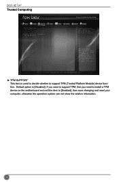
... F3: Optimized Defaults F4: Save & Exit ESC/Right Click: Exit Version 2.14.1219. Copyright (C) 2012 American Megatrends, Inc. ► TPM SUPPORT This item is used to decide whether to [Enabled], then save changing and reset your computer, otherwise the operation system can not show TPM.Reset of platform is [Disabled]. BIOS SETUP Trusted Computing Main F-center Advanced Boot TPM Configuration TPM SUPPORT Current TPM Status...
... F3: Optimized Defaults F4: Save & Exit ESC/Right Click: Exit Version 2.14.1219. Copyright (C) 2012 American Megatrends, Inc. ► TPM SUPPORT This item is used to decide whether to [Enabled], then save changing and reset your computer, otherwise the operation system can not show TPM.Reset of platform is [Disabled]. BIOS SETUP Trusted Computing Main F-center Advanced Boot TPM Configuration TPM SUPPORT Current TPM Status...
User manual
Page 47
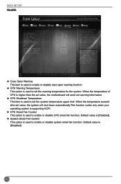
... function works only when your operating system is supporting ACPI. ► CPU Smart Fan Control This option is used to enable or disable CPU smart fan function. Default value is used to enable or disable case open chassis, Instruction Alarm will appear all the time. → ←: Select Screen ↑ ↓/Click: Select Item Enter/Dbl Click: Select +/-: Change Opt. BIOS SETUP Health Main F-center Advanced Boot Case Open Warning CPU Temperature System Temperature CPU Fan Speed System Fan Speed CPU Vcore DRAM Voltage +12V SYS +5V SYS VBAT CPU Warning Temperature CPU...
... function works only when your operating system is supporting ACPI. ► CPU Smart Fan Control This option is used to enable or disable CPU smart fan function. Default value is used to enable or disable case open chassis, Instruction Alarm will appear all the time. → ←: Select Screen ↑ ↓/Click: Select Item Enter/Dbl Click: Select +/-: Change Opt. BIOS SETUP Health Main F-center Advanced Boot Case Open Warning CPU Temperature System Temperature CPU Fan Speed System Fan Speed CPU Vcore DRAM Voltage +12V SYS +5V SYS VBAT CPU Warning Temperature CPU...
User manual
Page 51
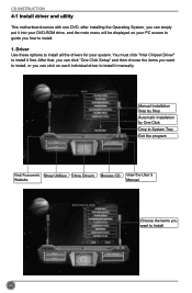
... Foxconn's Show Utilities Show Drivers Browse CD View the User's Website Manual Choose the items you want to install, or you how to Install 44 After that, you can click "One Click Setup" and then choose the items you want to install. 1. Driver Use these options to install all the drivers for your PC screen to guide you can simply put it into your DVD-ROM drive, and the main menu...
... Foxconn's Show Utilities Show Drivers Browse CD View the User's Website Manual Choose the items you want to install, or you how to Install 44 After that, you can click "One Click Setup" and then choose the items you want to install. 1. Driver Use these options to install all the drivers for your PC screen to guide you can simply put it into your DVD-ROM drive, and the main menu...
User manual
Page 52
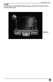
Click here 45 CD INSTRUCTION 2. Utility Use these options to install additional software programs. And click "User's manual" button to view the product manual.
Click here 45 CD INSTRUCTION 2. Utility Use these options to install additional software programs. And click "User's manual" button to view the product manual.


