User Manual
Page 137
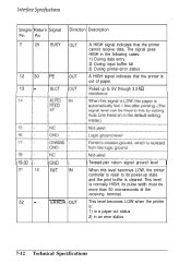
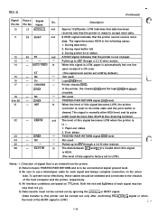
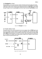
...receive data. OUT Pulled up to 5V through 3.3 kR Twisted-pair return signal ground level 16 INIT IN When this level becomes LOW, the printer controller is reset to its pulse width must be more than 50 microseconds at the receiving terminal. 32 - -__ ERROR OUT This level becomes LOW when ...the printer is out of paper. The signal goes HIGH in an error status 7-12 Technical Specifications its power-up state and the print buffer is...
...receive data. OUT Pulled up to 5V through 3.3 kR Twisted-pair return signal ground level 16 INIT IN When this level becomes LOW, the printer controller is reset to its pulse width must be more than 50 microseconds at the receiving terminal. 32 - -__ ERROR OUT This level becomes LOW when ...the printer is out of paper. The signal goes HIGH in an error status 7-12 Technical Specifications its power-up state and the print buffer is...
User Manual
Page 143
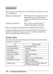
... paper position Cancelled 1/6-inch line spacing Cleared Every eight characters Channel 0 Reset to a fixed set . Item Top-of conditions): Hardware initialization When the power is initialized. These two kinds of all text. Software initialization When software sends the ESC @ (initialize the printer) command. Also, software initialization does not clear the data buffer...
... paper position Cancelled 1/6-inch line spacing Cleared Every eight characters Channel 0 Reset to a fixed set . Item Top-of conditions): Hardware initialization When the power is initialized. These two kinds of all text. Software initialization When software sends the ESC @ (initialize the printer) command. Also, software initialization does not clear the data buffer...
User Manual
Page 158
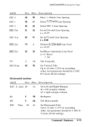
...-inch Line Spacing n = O-255 ESC A n 65 41 Set n/72-inch Line Spacing n = O-85 ESCJn 74 A Perform n/ 216-inch Line Feed n = O-255 ESC5n 53 35 Set/Reset Automatic Line Feed n = 0: Reset 1: Set VT 11 OB Tab Vertically ESC B nn 66 42 Set Vertical Tabs Up to 32 tabs (1 255) in ascending order;
...-inch Line Spacing n = O-255 ESC A n 65 41 Set n/72-inch Line Spacing n = O-85 ESCJn 74 A Perform n/ 216-inch Line Feed n = O-255 ESC5n 53 35 Set/Reset Automatic Line Feed n = 0: Reset 1: Set VT 11 OB Tab Vertically ESC B nn 66 42 Set Vertical Tabs Up to 32 tabs (1 255) in ascending order;
User Manual
Page 159
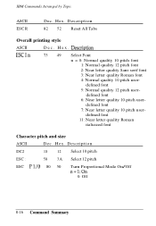
IBM Commands Arranged by Topic ASCII ESC R Dec. Description 82 52 Reset All Tabs Overall printing style ASCII D e c . H e x . Description DC2 18 12 Select 10 pitch ESC : 58 3A Select 12 pitch ESC I'l/O 80 50 Turn Proportional Mode ...
IBM Commands Arranged by Topic ASCII ESC R Dec. Description 82 52 Reset All Tabs Overall printing style ASCII D e c . H e x . Description DC2 18 12 Select 10 pitch ESC : 58 3A Select 12 pitch ESC I'l/O 80 50 Turn Proportional Mode ...
User Manual
Page 176
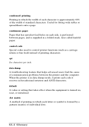
... codes used to control printer functions (such as a carriage return or line feed) instead of individual dots. data dump A troubleshooting feature that has sprocket-feed holes on , reset, or initialized. condensed printing Printing in which the width of each character is approximately 60% of the width of standard characters. dot matrix A method of printing in...
... codes used to control printer functions (such as a carriage return or line feed) instead of individual dots. data dump A troubleshooting feature that has sprocket-feed holes on , reset, or initialized. condensed printing Printing in which the width of each character is approximately 60% of the width of standard characters. dot matrix A method of printing in...

User Manual
Page 179
...by sending a command, an INIT signal, or by turning the printer off . The portion of the printer's memory used as word processing or financial planning. superscript Printing in the upper part of the printer. reset To return a printer to the loading position. All data stored in RAM is lost ...when the printer is printed at about two-thirds the normal height in which each character is turned...
...by sending a command, an INIT signal, or by turning the printer off . The portion of the printer's memory used as word processing or financial planning. superscript Printing in the upper part of the printer. reset To return a printer to the loading position. All data stored in RAM is lost ...when the printer is printed at about two-thirds the normal height in which each character is turned...
Service Manual
Page 25
.... (Data transfer to this signal is out of this signal becomes LOW, the printer controller is reset to its initial state and the print buffer is normally atthe HIGH level, and... its pulse width must be less than 50 ps at signal ground level. 3) Be sure to LOW.) . Printer chassis GND. In the printer...cable for each signal must not be connected at the receiving terminal. When this signal becomes LOW when the printer is in the following cases: 1. Not used . Ov - 17 - GND - 31 - SLCT IN ...
.... (Data transfer to this signal is out of this signal becomes LOW, the printer controller is reset to its initial state and the print buffer is normally atthe HIGH level, and... its pulse width must be less than 50 ps at signal ground level. 3) Be sure to LOW.) . Printer chassis GND. In the printer...cable for each signal must not be connected at the receiving terminal. When this signal becomes LOW when the printer is in the following cases: 1. Not used . Ov - 17 - GND - 31 - SLCT IN ...
Service Manual
Page 35
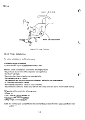
... to the default value set to every 8 columns. Lever Positions 1.5.12 Printer Initialization The printer is initialized in the following cases. (1) When the printer is turned on (2) INIT signal or CMREQ (optional I/F) (3) Sofiware reSet command (ESC @) (4) Page length command (ESC C) NOTE: The CMREQ...their default values. q All vertical tab positions are set from the optional card to 1/6 inch. TOF position will be reset in non-volatile memory. q The printer clears the print buffer and input data buffer. q The horizontal tab positions are cleared. r' Platen Gap Adjust Lever 4.-...
... to the default value set to every 8 columns. Lever Positions 1.5.12 Printer Initialization The printer is initialized in the following cases. (1) When the printer is turned on (2) INIT signal or CMREQ (optional I/F) (3) Sofiware reSet command (ESC @) (4) Page length command (ESC C) NOTE: The CMREQ...their default values. q All vertical tab positions are set from the optional card to 1/6 inch. TOF position will be reset in non-volatile memory. q The printer clears the print buffer and input data buffer. q The horizontal tab positions are cleared. r' Platen Gap Adjust Lever 4.-...
Service Manual
Page 42
... REV.-A 2.1 Printer Mechanism Operation 2. .-.1 2.1.1 Printhead Mechanism 2. .-.1 2.1.2 Carriage Mechanism 2. .-.3 2.1.3 Platen Gap Adjustment 2. . -. 4 2.1.4 Paper Handling Mechanisms 2. .-5 2.1.4.1 Paper Feed Mechanisms 2. .-5 2.1.4.2 Paper Advance Mechanisms 2. . -6 2.1.4.3 Paper Paths 2. .-.13 2.1.4 Ribbon Advance Mechanism 2. .-18 2.2 Power Supply Operation 2. .-19 2.2.1 Power Supply Overview 2. .-19 2.2.2 Power Supply Circuit Operation 2. .-20 2.3 Control Circuit Operation 2. .-.22 2.3.1 Control Circuit Operation Overview 2. . -22 2.3.2 Reset Circuit 2. .-.25...
... REV.-A 2.1 Printer Mechanism Operation 2. .-.1 2.1.1 Printhead Mechanism 2. .-.1 2.1.2 Carriage Mechanism 2. .-.3 2.1.3 Platen Gap Adjustment 2. . -. 4 2.1.4 Paper Handling Mechanisms 2. .-5 2.1.4.1 Paper Feed Mechanisms 2. .-5 2.1.4.2 Paper Advance Mechanisms 2. . -6 2.1.4.3 Paper Paths 2. .-.13 2.1.4 Ribbon Advance Mechanism 2. .-18 2.2 Power Supply Operation 2. .-19 2.2.1 Power Supply Overview 2. .-19 2.2.2 Power Supply Circuit Operation 2. .-20 2.3 Control Circuit Operation 2. .-.22 2.3.1 Control Circuit Operation Overview 2. . -22 2.3.2 Reset Circuit 2. .-.25...
Service Manual
Page 43
... Tractor Operation Using the Bottom Paper Entrance 2-9 Figure 2-8. Release Lever Setting Function 2. .-12 Figure 2-12. Power Supply Circuit Block Diagram 2. .-21 Figure 2-23. Power On Reset Circuit 2. . -. 25 figure 2-26. Friction Advance Operation UsingtheTop Paper Entrance ...........2-6 Figure 2-5. Paper Feed Methods and Paper Entrances 2-5 Table 2-2. REV.-A LIST OF FIGURES Figure 2-l. Push Tractor...
... Tractor Operation Using the Bottom Paper Entrance 2-9 Figure 2-8. Release Lever Setting Function 2. .-12 Figure 2-12. Power Supply Circuit Block Diagram 2. .-21 Figure 2-23. Power On Reset Circuit 2. . -. 25 figure 2-26. Friction Advance Operation UsingtheTop Paper Entrance ...........2-6 Figure 2-5. Paper Feed Methods and Paper Entrances 2-5 Table 2-2. REV.-A LIST OF FIGURES Figure 2-l. Push Tractor...

Service Manual
Page 44
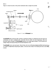
...(2) Thisinducedforce causesthe plate toapproach the coil rod andtheassociated dotwire is switched off, the force induced in this way prints a dot on the platen. (3) The dot wire presses the ink ribbon up against the paper as the current through the action of the plate spring. The plate ...and the platen. The printhead contains a column of the FX-870/l 170 printer and explains how the printer works. The four steps below . 2.1.1 Printhead Mechanism The printhead mechanism consists of hitting the platen works with the wire resetting spring to pull the wire back to the printhead drive ...
...(2) Thisinducedforce causesthe plate toapproach the coil rod andtheassociated dotwire is switched off, the force induced in this way prints a dot on the platen. (3) The dot wire presses the ink ribbon up against the paper as the current through the action of the plate spring. The plate ...and the platen. The printhead contains a column of the FX-870/l 170 printer and explains how the printer works. The four steps below . 2.1.1 Printhead Mechanism The printhead mechanism consists of hitting the platen works with the wire resetting spring to pull the wire back to the printhead drive ...
Service Manual
Page 45
...impacting the platen, so that can detect the head temperature. To minimize the dot wire drive coil overheating, the head is equipped with a thermistor that the wires vibrate. Dot Wire Wire Resetting Spring Stopper \ \ Ribbon Mask Platen )b .ctuatlngT:-Rbf)cl Paper B$l=...lieaclDrivingCOil Actuating Plate Spring Figure 2-1. The printhead tends to heat up after a period of the printer mechanism when a single dot is also used asa buzzer...
...impacting the platen, so that can detect the head temperature. To minimize the dot wire drive coil overheating, the head is equipped with a thermistor that the wires vibrate. Dot Wire Wire Resetting Spring Stopper \ \ Ribbon Mask Platen )b .ctuatlngT:-Rbf)cl Paper B$l=...lieaclDrivingCOil Actuating Plate Spring Figure 2-1. The printhead tends to heat up after a period of the printer mechanism when a single dot is also used asa buzzer...

Service Manual
Page 68
... 2-25. A similar integration circuit is sent from the host computer. This low level is used as a reset signal. (2) INIT signal reset The reset signal is also issued when the INIT signal is provided in the gate array and further delays the output of the ROUT signal. Figure 2-25 ...shows the power on the gate array does not reach +5 VDC until capacitor C24 is fully charged. Power On Reset Circuit 2-25 Because it takes a moment for the voltage at ZD2 to reach +31.5 V, the voltage at the DISC terminal on...
... 2-25. A similar integration circuit is sent from the host computer. This low level is used as a reset signal. (2) INIT signal reset The reset signal is also issued when the INIT signal is provided in the gate array and further delays the output of the ROUT signal. Figure 2-25 ...shows the power on the gate array does not reach +5 VDC until capacitor C24 is fully charged. Power On Reset Circuit 2-25 Because it takes a moment for the voltage at ZD2 to reach +31.5 V, the voltage at the DISC terminal on...
Service Manual
Page 72
... and, on completion of the +35 V line. The pulse length is adjusted referring to the voltage of the reading, resets the BUSY signal to enable the host computer to print each dot. When a STROBE signal is sent from the host computer. The CPU then reads the data latched into the gate array...
... and, on completion of the +35 V line. The pulse length is adjusted referring to the voltage of the reading, resets the BUSY signal to enable the host computer to print each dot. When a STROBE signal is sent from the host computer. The CPU then reads the data latched into the gate array...
Service Manual
Page 118
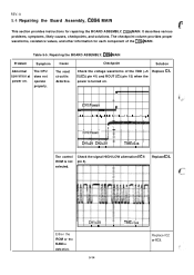
... power on . The CPU does not operate properly. A 1 I I I I I I 1 II I I I I I I 1 II Ill I 1 I [1 1 I I I I 1 II I I I 1 1 Replace IC2 or IC3. 5-14 IS 1I The control ROM is defective. The reset circuit is turned on . Replace IC4. ? -1- (CHl:Power) m ! The checkpoint column provides proper waveforms, resistance values, and other information for repairing the BOARD ASSEMBLY, C094...
... power on . The CPU does not operate properly. A 1 I I I I I I 1 II I I I I I I 1 II Ill I 1 I [1 1 I I I I 1 II I I I 1 1 Replace IC2 or IC3. 5-14 IS 1I The control ROM is defective. The reset circuit is turned on . Replace IC4. ? -1- (CHl:Power) m ! The checkpoint column provides proper waveforms, resistance values, and other information for repairing the BOARD ASSEMBLY, C094...
Service Manual
Page 132
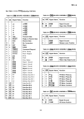
... 1/0 D4 33 1/0 D3 34 1/0 D2 35 1/0 D1 36 1/0 DO +5 VDC +5 VDC +5 VDC +5 VDC +5 VDC +5 VDC Transmit Data Ready to Receive Data Receive Data No Connection Reset Inhibit Command Request Write Ready Read Request Write Read Chip Select Signal Ground Signal Ground Signal Ground Signal Ground Signal Ground Signal Ground Address Bus...
... 1/0 D4 33 1/0 D3 34 1/0 D2 35 1/0 D1 36 1/0 DO +5 VDC +5 VDC +5 VDC +5 VDC +5 VDC +5 VDC Transmit Data Ready to Receive Data Receive Data No Connection Reset Inhibit Command Request Write Ready Read Request Write Read Chip Select Signal Ground Signal Ground Signal Ground Signal Ground Signal Ground Signal Ground Address Bus...


