
Product Brochure
Page 8
... lab quality prints at 360 x 360 dpi 28 billion shots per nozzle ~2,000 times (coated media) Pump unit, flushing box, head cleaner, cap assembly Electrical Requirements Voltage 120 V (100 to 240 V) Frequency 50 to 100' (limited by roll ..."(H) x 22.5"(D) 49.2"(H) with optional printer stand Printer weight: 96 lb SP9600 63.9"(W) x 46.4"(H) x 28.2"(D) Printer weight: 185 lb with optional software RIP. EPSON Stylus Pro 7600 & 9600 Print Engine Specifications Printing Method 7-color (CcMmYKk) EPSON UltraChrome Ink or 6-color (CcMmYKK) EPSON Photographic Dye Ink Variable Droplet Micro Piezo...
... lab quality prints at 360 x 360 dpi 28 billion shots per nozzle ~2,000 times (coated media) Pump unit, flushing box, head cleaner, cap assembly Electrical Requirements Voltage 120 V (100 to 240 V) Frequency 50 to 100' (limited by roll ..."(H) x 22.5"(D) 49.2"(H) with optional printer stand Printer weight: 96 lb SP9600 63.9"(W) x 46.4"(H) x 28.2"(D) Printer weight: 185 lb with optional software RIP. EPSON Stylus Pro 7600 & 9600 Print Engine Specifications Printing Method 7-color (CcMmYKk) EPSON UltraChrome Ink or 6-color (CcMmYKK) EPSON Photographic Dye Ink Variable Droplet Micro Piezo...

Product Information Guide
Page 1
...nozzle Periodic maintenance Pump unit, head cleaner, and cap assembly require replacement approximately every 2 years based on 25% duty cycle Cutter blade life Approximately 2000 B0+ sheets (EPSON media up to 4.33 mil thick); EPSON Stylus Pro 7600 and 9600 - ink cartridge... compartment roll paper cover paper set lever optional interface shield plate AC inlet USB interface connector parallel interface connector Printer Specifications Printing Printing method 7 color EPSON UltraChrome ink or 6 color EPSON...
...nozzle Periodic maintenance Pump unit, head cleaner, and cap assembly require replacement approximately every 2 years based on 25% duty cycle Cutter blade life Approximately 2000 B0+ sheets (EPSON media up to 4.33 mil thick); EPSON Stylus Pro 7600 and 9600 - ink cartridge... compartment roll paper cover paper set lever optional interface shield plate AC inlet USB interface connector parallel interface connector Printer Specifications Printing Printing method 7 color EPSON UltraChrome ink or 6 color EPSON...
User Manual
Page 181
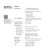
Printing Printing method 7 color EPSON UltraChrome ink or 6 color EPSON Photographic Dye ink Nozzle configuration Maximum print speed Maximum resolution Engine reliability Total print volume Print head life Periodic maintenance (pump unit, head cleaner, cap assembly) Cutter blade life (... Appendix A: Specifications Note Additional specifications are provided in 1/1440-inch increments 32MB (Stylus Pro 7600) 64MB (Stylus Pro 9600) 181 approximately 1,000 B0+ film sheets Bidirectional EPSON ESC/P® Raster Photographic Driver 215 ± 10 milliseconds per nozzle Requires replacement ...
Printing Printing method 7 color EPSON UltraChrome ink or 6 color EPSON Photographic Dye ink Nozzle configuration Maximum print speed Maximum resolution Engine reliability Total print volume Print head life Periodic maintenance (pump unit, head cleaner, cap assembly) Cutter blade life (... Appendix A: Specifications Note Additional specifications are provided in 1/1440-inch increments 32MB (Stylus Pro 7600) 64MB (Stylus Pro 9600) 181 approximately 1,000 B0+ film sheets Bidirectional EPSON ESC/P® Raster Photographic Driver 215 ± 10 milliseconds per nozzle Requires replacement ...

Service Manual
Page 9
EPSON Stylus Pro 7600/9600 Revision A 4.3 Disassembly and Assembly of Carriage (CR) Mechanism 171 4.3.1 Print Head 171 4.3.2 Damper ASSY 173 4.3.3 CR Board ASSY 174 4.3.4 Cutter Section 175 4.3.4.1 Cutter...Board 192 4.5.2 I/H (Ink Holder) ASSY 193 4.5.3 Cover Sensor ASSY 197 4.6 Disassembly and Assembly of Cleaning Mechanism 198 4.6.1 Maintenance ASSY Removal 199 4.6.2 Pump Motor ASSY 200 4.6.3 Cap ASSY 200 4.6.4 Pump ASSY 201 4.6.5 Cleaner Head (Wiper 203 4.6.6 Flushing Box ASSY 204 4.7 Disassembly and Assembly of Circuit Boards 205 4.7.1 Power Supply Board 205 4.7.2 AC Inlet...
EPSON Stylus Pro 7600/9600 Revision A 4.3 Disassembly and Assembly of Carriage (CR) Mechanism 171 4.3.1 Print Head 171 4.3.2 Damper ASSY 173 4.3.3 CR Board ASSY 174 4.3.4 Cutter Section 175 4.3.4.1 Cutter...Board 192 4.5.2 I/H (Ink Holder) ASSY 193 4.5.3 Cover Sensor ASSY 197 4.6 Disassembly and Assembly of Cleaning Mechanism 198 4.6.1 Maintenance ASSY Removal 199 4.6.2 Pump Motor ASSY 200 4.6.3 Cap ASSY 200 4.6.4 Pump ASSY 201 4.6.5 Cleaner Head (Wiper 203 4.6.6 Flushing Box ASSY 204 4.7 Disassembly and Assembly of Circuit Boards 205 4.7.1 Power Supply Board 205 4.7.2 AC Inlet...

Service Manual
Page 53
...E F 60 ~ 41% E∗∗∗ F 40 ~ 21% E∗∗ F 20% ~ 1% E∗ F Less than 1% remaining FF „ Maintenance Req. Cap assembly, pump assembly, flushing box, and wiper are displayed on these indications. Do not inform users of the meaning of these values is detected with rear sensor...pump motor life. When the life is TBD%, maintenance request happens. „ Fatal error When the life is 0%, service request happens. „ Counter clear When "CLEAR COUNTERS CLEANER2 in Maintenance mode 2 is executed, the counter is same as PF motor. EPSON Stylus Pro 7600/9600...
...E F 60 ~ 41% E∗∗∗ F 40 ~ 21% E∗∗ F 20% ~ 1% E∗ F Less than 1% remaining FF „ Maintenance Req. Cap assembly, pump assembly, flushing box, and wiper are displayed on these indications. Do not inform users of the meaning of these values is detected with rear sensor...pump motor life. When the life is TBD%, maintenance request happens. „ Fatal error When the life is 0%, service request happens. „ Counter clear When "CLEAR COUNTERS CLEANER2 in Maintenance mode 2 is executed, the counter is same as PF motor. EPSON Stylus Pro 7600/9600...
Service Manual
Page 115
...Revision A Cleaning Mechanism (Maintenance ASSY) Maintenance Tank Figure 2-14. Cleaning Mechanism Components Pump assembly Flushing box Head cleaner CR Lock Pump motor Cap assembly Figure 2-15. The cleaning mechanism components are installed above , given only ...Stylus Pro 5000/9000. The waste ink from the cleaning mechanism is channeled to the waste ink pad (Maintenance Tank) in the lower right side through one small tube to wipe or rub off ink and foreign materials from the nozzles. EPSON Stylus Pro 7600/9600 2.2.3 Cleaning Mechanism The cleaning mechanism in this printer...
...Revision A Cleaning Mechanism (Maintenance ASSY) Maintenance Tank Figure 2-14. Cleaning Mechanism Components Pump assembly Flushing box Head cleaner CR Lock Pump motor Cap assembly Figure 2-15. The cleaning mechanism components are installed above , given only ...Stylus Pro 5000/9000. The waste ink from the cleaning mechanism is channeled to the waste ink pad (Maintenance Tank) in the lower right side through one small tube to wipe or rub off ink and foreign materials from the nozzles. EPSON Stylus Pro 7600/9600 2.2.3 Cleaning Mechanism The cleaning mechanism in this printer...

Service Manual
Page 116
...the capped position during paper cutting, etc. Operating Principles Print Mechanism Components 116 Also, the print head is in the pump unit so that the nozzles don't clog. When the first ink cartridge is inserted (after all 6 colors ...EPSON Stylus Pro 7600/9600 † Cap assembly When not printing, the print head (should) rest on . † Flushing box Flushing (dummy printing) is performed over the print head nozzles when entering a shutdown operation. Capping In order to prevent the ink viscosity from increasing while it is being kept, a rubber cap is set when the printer...
...the capped position during paper cutting, etc. Operating Principles Print Mechanism Components 116 Also, the print head is in the pump unit so that the nozzles don't clog. When the first ink cartridge is inserted (after all 6 colors ...EPSON Stylus Pro 7600/9600 † Cap assembly When not printing, the print head (should) rest on . † Flushing box Flushing (dummy printing) is performed over the print head nozzles when entering a shutdown operation. Capping In order to prevent the ink viscosity from increasing while it is being kept, a rubber cap is set when the printer...

Service Manual
Page 133
... 2 [CLEAR COUNTERS / RTC] (NA) 0 (NA) 0 (NA) 1 0 0 0 (RSVD) 0020 The number of 28 billion shots/nozzle. „ A cap, pump, pump motor, wiper, flushing box are replaced together when replacing the cleaning unit. Life end Print head - Continue) *1 CR Motor - AGC error) *1 Battery empty (Nozzle check...*1 Not applicable to maintain it. † Recovery This message is cleared only when the printer is maintained by the code "nnnn" is almost run out. Life end (Dot missing detector - EPSON Stylus Pro 7600/9600 Revision A † LED STATUS Paper Out LED goes on at the time of shots ...
... 2 [CLEAR COUNTERS / RTC] (NA) 0 (NA) 0 (NA) 1 0 0 0 (RSVD) 0020 The number of 28 billion shots/nozzle. „ A cap, pump, pump motor, wiper, flushing box are replaced together when replacing the cleaning unit. Life end Print head - Continue) *1 CR Motor - AGC error) *1 Battery empty (Nozzle check...*1 Not applicable to maintain it. † Recovery This message is cleared only when the printer is maintained by the code "nnnn" is almost run out. Life end (Dot missing detector - EPSON Stylus Pro 7600/9600 Revision A † LED STATUS Paper Out LED goes on at the time of shots ...

Service Manual
Page 147
... may occur with a specific ink color: • Abnormal connections between the pump motor and pump unit has been assembled improperly. • If the cap assembly has failed. (The tension spring has come off , the cap rubber is kept for those errors....printer and the troubleshooting points for a long time without being used, the viscosity of the ink on Your Printout 147 Therefore, check the counter indication (remaining value) beforehand. (If deemed necessary, prepare another Maintenance Tank as a spare.) † The actions above do not work to leak, etc. EPSON Stylus Pro 7600/9600...
... may occur with a specific ink color: • Abnormal connections between the pump motor and pump unit has been assembled improperly. • If the cap assembly has failed. (The tension spring has come off , the cap rubber is kept for those errors....printer and the troubleshooting points for a long time without being used, the viscosity of the ink on Your Printout 147 Therefore, check the counter indication (remaining value) beforehand. (If deemed necessary, prepare another Maintenance Tank as a spare.) † The actions above do not work to leak, etc. EPSON Stylus Pro 7600/9600...

Service Manual
Page 157
EPSON Stylus Pro 7600/9600 Revision A 4.2.3 L Side Cover (p.163) 4.2.4 I/H Cover (p.164) 4.2.1 Panel Unit (p.159) 4.2.2 R Side Cover (p.160) 4.2.8 Roll Paper Cover (p.169) 4.2.9 Front Cover (p.170) 4.2.7 Paper ... Box ASSY (p204) 4.3.6 P_EGDE Sensor ASSY (p.179) 4.3.7 CR Motor ASSY (p.180) 4.3.8 HEAD_SLIDE Sensor ASSY (p.182) 4.6.1 Maintenance ASSY Removal (p.199) 4.6.2 Pump Motor ASSY (p.200) 4.6.3 Cap ASSY (p.200) 4.6.4 Pump ASSY (p.201) 4.6.5 Cleaner Head (Wiper) (p.203) 4.3.10 CR Encoder Scale (Timing Fence) (p.184) 4.4.5 P_THICK Sensor/P_THICK Sensor_0.3 ASSY (p.190) 4.4.6 P_REAR...
EPSON Stylus Pro 7600/9600 Revision A 4.2.3 L Side Cover (p.163) 4.2.4 I/H Cover (p.164) 4.2.1 Panel Unit (p.159) 4.2.2 R Side Cover (p.160) 4.2.8 Roll Paper Cover (p.169) 4.2.9 Front Cover (p.170) 4.2.7 Paper ... Box ASSY (p204) 4.3.6 P_EGDE Sensor ASSY (p.179) 4.3.7 CR Motor ASSY (p.180) 4.3.8 HEAD_SLIDE Sensor ASSY (p.182) 4.6.1 Maintenance ASSY Removal (p.199) 4.6.2 Pump Motor ASSY (p.200) 4.6.3 Cap ASSY (p.200) 4.6.4 Pump ASSY (p.201) 4.6.5 Cleaner Head (Wiper) (p.203) 4.3.10 CR Encoder Scale (Timing Fence) (p.184) 4.4.5 P_THICK Sensor/P_THICK Sensor_0.3 ASSY (p.190) 4.4.6 P_REAR...

Service Manual
Page 198
... box (FL BOX) (p.71)" in Maintenance mode 2. Major Parts of Cleaning Mechanism Names of Parts Pump Motor ASSY Cleaning Unit * Replace at the same time. EPSON Stylus Pro 7600/9600 4.6 Disassembly and Assembly of Cleaning Mechanism The Maintenance ASSY consists of the major assemblies listed below four ... by the life of Pump Motor ASSY life Pump/Cap ASSY Cleaner Head Cap ASSY Pump ASSY Flushing Box ASSY See p.200 p.200 p.201 p.203 p.204 A D JU S TM E N T R E Q U IR E D Once you have replaced the Cleaning Unit, be replaced singly. Replace the Cap ASSY, Pump ASSY, Flushing Box and...
... box (FL BOX) (p.71)" in Maintenance mode 2. Major Parts of Cleaning Mechanism Names of Parts Pump Motor ASSY Cleaning Unit * Replace at the same time. EPSON Stylus Pro 7600/9600 4.6 Disassembly and Assembly of Cleaning Mechanism The Maintenance ASSY consists of the major assemblies listed below four ... by the life of Pump Motor ASSY life Pump/Cap ASSY Cleaner Head Cap ASSY Pump ASSY Flushing Box ASSY See p.200 p.200 p.201 p.203 p.204 A D JU S TM E N T R E Q U IR E D Once you have replaced the Cleaning Unit, be replaced singly. Replace the Cap ASSY, Pump ASSY, Flushing Box and...

Service Manual
Page 199
... the Maintenance ASSY Cleaner Head (Wiper) (p.203) Valve ASSY Pump ASSY (p.201) Flushing Box ASSY Pump Motor ASSY (p.200) Waste ink tube Cap ASSY (p.200) Figure 4-73. EPSON Stylus Pro 7600/9600 4.6.1 Maintenance ASSY Removal CHECK P O IN T When you replace the Maintenance ASSY, ink can spill from the printer body. (See Figure 4-72) After installing the Maintenance ASSY...
... the Maintenance ASSY Cleaner Head (Wiper) (p.203) Valve ASSY Pump ASSY (p.201) Flushing Box ASSY Pump Motor ASSY (p.200) Waste ink tube Cap ASSY (p.200) Figure 4-73. EPSON Stylus Pro 7600/9600 4.6.1 Maintenance ASSY Removal CHECK P O IN T When you replace the Maintenance ASSY, ink can spill from the printer body. (See Figure 4-72) After installing the Maintenance ASSY...

Service Manual
Page 200
...; Check that the valve part is not dislocated. Remove the Maintenance ASSY. (See p.199) 2. Remove the two screws securing the Cap ASSY and remove the Cap ASSY from the Maintenance ASSY. EPSON Stylus Pro 7600/9600 4.6.2 Pump Motor ASSY 1. Remove the Maintenance ASSY. (See p.199) 2. Removing the Cap ASSY Disassembly and Assembly of Cleaning Mechanism 200 Removing the...
...; Check that the valve part is not dislocated. Remove the Maintenance ASSY. (See p.199) 2. Remove the two screws securing the Cap ASSY and remove the Cap ASSY from the Maintenance ASSY. EPSON Stylus Pro 7600/9600 4.6.2 Pump Motor ASSY 1. Remove the Maintenance ASSY. (See p.199) 2. Removing the Cap ASSY Disassembly and Assembly of Cleaning Mechanism 200 Removing the...

Service Manual
Page 201
...77. Remove the one screw (M 3×6) and remove the Pump ASSY.(See Figure 4-77) A D J U S T M E N T Once you have replaced the Pump ASSY, execute "CLEAR R E Q U I R E D COUNTERS" (See p.71). Disconnect the tube from the Cap ASSY, remove the one central screw (M3×4) of Cleaning... (M3×6) on the gear side. 4. Removing the Pump ASSY 2/2 Disassembly and Assembly of the Pump ASSY and remove the three parts including the gear. (See Figure 4-76) 3. Gear (3 parts) Screw (M3×4) Revision A Screws (M3×6) ×2 Figure 4-76. EPSON Stylus Pro 7600/9600 4.6.4 Pump ASSY 1.
...77. Remove the one screw (M 3×6) and remove the Pump ASSY.(See Figure 4-77) A D J U S T M E N T Once you have replaced the Pump ASSY, execute "CLEAR R E Q U I R E D COUNTERS" (See p.71). Disconnect the tube from the Cap ASSY, remove the one central screw (M3×4) of Cleaning... (M3×6) on the gear side. 4. Removing the Pump ASSY 2/2 Disassembly and Assembly of the Pump ASSY and remove the three parts including the gear. (See Figure 4-76) 3. Gear (3 parts) Screw (M3×4) Revision A Screws (M3×6) ×2 Figure 4-76. EPSON Stylus Pro 7600/9600 4.6.4 Pump ASSY 1.

Service Manual
Page 203
... and Assembly of the Cleaner Head from your bare hand. „ Before use tweezers; EPSON Stylus Pro 7600/9600 4.6.5 Cleaner Head (Wiper) 1. Install the Cleaner Head in such an orientation that its felt is positioned on the Pump ASSY side and the rubber in on the Cleaner Head Holder and pull off the Cleaner... Head. Rubber side Cleaner Head Revision A Felt side Figure 4-78. For handling the Cleaner Head, be stopped up with ink repelled by fat from the projection on the Cap ASSY side....
... and Assembly of the Cleaner Head from your bare hand. „ Before use tweezers; EPSON Stylus Pro 7600/9600 4.6.5 Cleaner Head (Wiper) 1. Install the Cleaner Head in such an orientation that its felt is positioned on the Pump ASSY side and the rubber in on the Cleaner Head Holder and pull off the Cleaner... Head. Rubber side Cleaner Head Revision A Felt side Figure 4-78. For handling the Cleaner Head, be stopped up with ink repelled by fat from the projection on the Cap ASSY side....

Service Manual
Page 277
...condition of loop scale (worn, etc.) • Check the condition of Periodically Replaced Components and Maintenance Cutter SPro7600/9600 Maintenance Tank SPro9600 SPro7600 Cleaning Unit SPro9600 SPro7600 CR Motor SPro9600 SPro7600 PF Motor SPro9600 SPro7600 1000 pages Film media... Tank 1. CR Motor 2. Driven Pulley At second SR: 1. Adj: Input Rank 2. EPSON Stylus Pro 7600/9600 Revision A Print Volume (# of sheet) Product Life (Specification) Table 6-1. Stylus Pro 7600/9600 - Driven Pulley 3. CR Belt Tension ADJ 2. Pump&Cap Assy (CRU) (CRU) 2.
...condition of loop scale (worn, etc.) • Check the condition of Periodically Replaced Components and Maintenance Cutter SPro7600/9600 Maintenance Tank SPro9600 SPro7600 Cleaning Unit SPro9600 SPro7600 CR Motor SPro9600 SPro7600 PF Motor SPro9600 SPro7600 1000 pages Film media... Tank 1. CR Motor 2. Driven Pulley At second SR: 1. Adj: Input Rank 2. EPSON Stylus Pro 7600/9600 Revision A Print Volume (# of sheet) Product Life (Specification) Table 6-1. Stylus Pro 7600/9600 - Driven Pulley 3. CR Belt Tension ADJ 2. Pump&Cap Assy (CRU) (CRU) 2.
Service Manual
Page 319
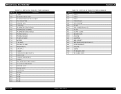
EPSON Stylus Pro 7600/9600 Table 7-6. ASP List for Stylus Pro 7600 (continued) Ref No. 672 LABEL Part Name 700 FLUSHING BOX ASSY. 701 PUMP MOTER JANCTION CABLE 702 TR CONNECTER 703 POROUS PAD 704 CLEANER 705 PUMP REDUCTION GEAR 1 706 POMP SHAFT STOPPER 707 PUMP REDUCTION GEAR 2 708 PG IDLE GEAR A 709 PG IDLE GEAR B 710 PUMP CAP ASSY. 711 MOTOR...
EPSON Stylus Pro 7600/9600 Table 7-6. ASP List for Stylus Pro 7600 (continued) Ref No. 672 LABEL Part Name 700 FLUSHING BOX ASSY. 701 PUMP MOTER JANCTION CABLE 702 TR CONNECTER 703 POROUS PAD 704 CLEANER 705 PUMP REDUCTION GEAR 1 706 POMP SHAFT STOPPER 707 PUMP REDUCTION GEAR 2 708 PG IDLE GEAR A 709 PG IDLE GEAR B 710 PUMP CAP ASSY. 711 MOTOR...
Service Manual
Page 321
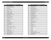
EPSON Stylus Pro 7600/9600 Table 7-7. ASP List for Stylus Pro 9600 (continued) Ref No. ASP List for Stylus Pro 9600 (continued) Ref No. 615 CABLE CLAMP Part Name 616 EDGE CLAMP 617 PRESS IDLE GEAR 618 PRESS SHAFT TRAY 619 PRESS TRANSMISSION GEAR 620 PRESS ...L 656 POROUS PAD CAP B 657 PROUSPAD C 658 PAETITION PLATE R ASSY. 659 TAPE 660 POROUS PAD 661 PAPER GUIDE WIRE 662 POROUS PAD 663 TAPE 664 PCB ASSY.I/C 665 M.T FFC2 666 POROUS PAD ASSY. 668 LABEL 669 LABEL 670 LABEL 671 LABEL 672 LABEL 700 FLUSHING BOX ASSY. 701 PUMP MOTER JANCTION CABLE...
EPSON Stylus Pro 7600/9600 Table 7-7. ASP List for Stylus Pro 9600 (continued) Ref No. ASP List for Stylus Pro 9600 (continued) Ref No. 615 CABLE CLAMP Part Name 616 EDGE CLAMP 617 PRESS IDLE GEAR 618 PRESS SHAFT TRAY 619 PRESS TRANSMISSION GEAR 620 PRESS ...L 656 POROUS PAD CAP B 657 PROUSPAD C 658 PAETITION PLATE R ASSY. 659 TAPE 660 POROUS PAD 661 PAPER GUIDE WIRE 662 POROUS PAD 663 TAPE 664 PCB ASSY.I/C 665 M.T FFC2 666 POROUS PAD ASSY. 668 LABEL 669 LABEL 670 LABEL 671 LABEL 672 LABEL 700 FLUSHING BOX ASSY. 701 PUMP MOTER JANCTION CABLE...

Service Manual
Page 322
EPSON Stylus Pro 7600/9600 Table 7-7. ASP List for Stylus Pro 9600 (continued) Ref No. 704 CLEANER Part Name 705 PUMP REDUCTION GEAR 1 706 POMP SHAFT STOPPER 707 PUMP REDUCTION GEAR 2 708 PG IDLE GEAR A 709 PG IDLE GEAR B 710 PUMP CAP ASSY. 711 MOTOR 712 CAP ASSY. 750 I/H INK FFC ASSY. 751 BOARD ASSY. 752...TUBE 802 TUBE 803 TUBE 804 TUBE 805 TUBE 806 TUBE 807 TUBE FILME 808 SUS SUPPORT Revision A Table 7-7. ASP List for Stylus Pro 9600 (continued) Ref No. 809 FILME Part Name 810 FLAT CORE(SSC-40-12) 811 FILME 812 CR FFC 1 ASSY. 813 ...
EPSON Stylus Pro 7600/9600 Table 7-7. ASP List for Stylus Pro 9600 (continued) Ref No. 704 CLEANER Part Name 705 PUMP REDUCTION GEAR 1 706 POMP SHAFT STOPPER 707 PUMP REDUCTION GEAR 2 708 PG IDLE GEAR A 709 PG IDLE GEAR B 710 PUMP CAP ASSY. 711 MOTOR 712 CAP ASSY. 750 I/H INK FFC ASSY. 751 BOARD ASSY. 752...TUBE 802 TUBE 803 TUBE 804 TUBE 805 TUBE 806 TUBE 807 TUBE FILME 808 SUS SUPPORT Revision A Table 7-7. ASP List for Stylus Pro 9600 (continued) Ref No. 809 FILME Part Name 810 FLAT CORE(SSC-40-12) 811 FILME 812 CR FFC 1 ASSY. 813 ...
