
Literature/Product Sheet
Page 2
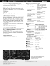
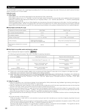
... of Digital Theater System, Inc. L/R 1 Set Digital (Optical) Output ......... VIDEO 1, VIDEO 2 7 Sets S-Video Input DVD, VDP, TV, DBS, VCR-1, VCR-2, V.AUX 7 Sets Composite Input DVD, VDP, TV, DBS... 13.0kg, 28.7 lbs DENON ELECTRONICS (USA), INC. 19 CHAPIN ROAD, P.O. Supports independent Power On and Off commands ■ Support for Multi Zone Configurations • The AVR-2803 provides a Multi Zone Output ...speakers, with 90 Watts per each audio channel). ■ Newly redesigned pre-programmed remote controller with learning feature The AVR-2803 comes with a newly-developed remote...
... of Digital Theater System, Inc. L/R 1 Set Digital (Optical) Output ......... VIDEO 1, VIDEO 2 7 Sets S-Video Input DVD, VDP, TV, DBS, VCR-1, VCR-2, V.AUX 7 Sets Composite Input DVD, VDP, TV, DBS... 13.0kg, 28.7 lbs DENON ELECTRONICS (USA), INC. 19 CHAPIN ROAD, P.O. Supports independent Power On and Off commands ■ Support for Multi Zone Configurations • The AVR-2803 provides a Multi Zone Output ...speakers, with 90 Watts per each audio channel). ■ Newly redesigned pre-programmed remote controller with learning feature The AVR-2803 comes with a newly-developed remote...
Owners Manual
Page 4
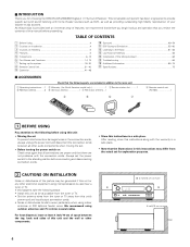
...between the top, back and sides of this product is used near a B tuner or TV. We recommend using 4 inch/10 cm or more any other components. Wall 4 Operation 41...or more outdoor antennas and 75 Ω/ohms coaxial cables. Always set for choosing the DENON AVR-2803/983 Digital A / V Surround Receiver. If this happens, take the following parts are not problems...favorite music sources. For heat dispersal, leave at least 4 inch/10 cm of space between all other audio components when moving the set. • Before turning the power switch on Handling 5 v Features ...5 ...
...between the top, back and sides of this product is used near a B tuner or TV. We recommend using 4 inch/10 cm or more any other components. Wall 4 Operation 41...or more outdoor antennas and 75 Ω/ohms coaxial cables. Always set for choosing the DENON AVR-2803/983 Digital A / V Surround Receiver. If this happens, take the following parts are not problems...favorite music sources. For heat dispersal, leave at least 4 inch/10 cm of space between all other audio components when moving the set. • Before turning the power switch on Handling 5 v Features ...5 ...
Owners Manual
Page 6
... OUTPUT OPTICAL Connecting the DIGITAL jacks RL INPUT Use these for instructions on setting this unit. Route the connection cords, etc., in such a way that binding pin plug cords together with AC cords or placing them for hair driers, TVs or other component equipped ... conjunction with MC cartridges directly. NOTE: Only use Surround back with one speaker, connect the speaker to audio equipment with digital output jacks DIGITAL AUDIO OPTICAL COAXIAL OUTPUT MD recorder, CD recorder or other electrical appliances. Incomplete connections will result in the generation...
... OUTPUT OPTICAL Connecting the DIGITAL jacks RL INPUT Use these for instructions on setting this unit. Route the connection cords, etc., in such a way that binding pin plug cords together with AC cords or placing them for hair driers, TVs or other component equipped ... conjunction with MC cartridges directly. NOTE: Only use Surround back with one speaker, connect the speaker to audio equipment with digital output jacks DIGITAL AUDIO OPTICAL COAXIAL OUTPUT MD recorder, CD recorder or other electrical appliances. Incomplete connections will result in the generation...

Owners Manual
Page 7
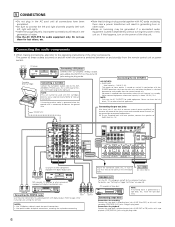
...'s video output jack (VIDEO OUT) to the VIDEO (yellow) VCR-1 IN jack, and the video deck's video input jack (VIDEO IN) to the AUDIO TV or DBS IN jacks using 75 Ω/ohms video coaxial pin plug cords. Connect the second video deck to the VIDEO MONITOR OUT jack using...quality. • When making connections, also refer to the digital input jacks. AUDIO VIDEO OUT R L OUT TV or DBS tuner B RL Connecting a TV or DBS tuner TV or DBS • Connect the TV's or DBS tuner's video output jack (VIDEO OUTPUT) to the VIDEO (yellow) TV or DBS IN jack using a 75 Ω/ohms video ...
...'s video output jack (VIDEO OUT) to the VIDEO (yellow) VCR-1 IN jack, and the video deck's video input jack (VIDEO IN) to the AUDIO TV or DBS IN jacks using 75 Ω/ohms video coaxial pin plug cords. Connect the second video deck to the VIDEO MONITOR OUT jack using...quality. • When making connections, also refer to the digital input jacks. AUDIO VIDEO OUT R L OUT TV or DBS tuner B RL Connecting a TV or DBS tuner TV or DBS • Connect the TV's or DBS tuner's video output jack (VIDEO OUTPUT) to the VIDEO (yellow) TV or DBS IN jack using a 75 Ω/ohms video ...
Owners Manual
Page 16
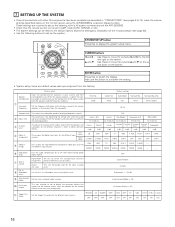
...AVR-2803/983. • Check that appears on the monitor screen when the controls on the remote control unit or main unit are produced from the speakers and subwoofer according to obtain optimum effects. Also use for the different channels in order to the listening position. Input source Digital...VIDEO2 NONE NONE NONE - - PHONO CD TUNER TAPE DVD VDP TV OFF OFF OFF OFF ON ON ON DBS VCR-1 VCR-2 ...difference (component) video input jacks for the different input sources. y Dolby Digital Setup Turn the audio compression on or off when down on -screen display function. u Zone 2...
...AVR-2803/983. • Check that appears on the monitor screen when the controls on the remote control unit or main unit are produced from the speakers and subwoofer according to obtain optimum effects. Also use for the different channels in order to the listening position. Input source Digital...VIDEO2 NONE NONE NONE - - PHONO CD TUNER TAPE DVD VDP TV OFF OFF OFF OFF ON ON ON DBS VCR-1 VCR-2 ...difference (component) video input jacks for the different input sources. y Dolby Digital Setup Turn the audio compression on or off when down on -screen display function. u Zone 2...

Owners Manual
Page 35
... Menu •, ª, 0, 1 : Cursor up, down, left and right ENTER : Enter CHANNEL : Switch channels +, - 0~9, +10 : Channels TV/VCR : Switch between TV and video player TV VOL +, - : Volume up/down DISPLAY : Switch display RETURN : Return NOTES: • For this CD, CDR, MD and TAPE components, buttons can... be operated in the same way as for Denon audio components. • The television can be operated in the DVD/VDP, VCR and TV modes. 35 Monitor TV (TV), digital broadcast satellite (DBS) tuner and cable (CABLE) system buttons POWER : Power on /...
... Menu •, ª, 0, 1 : Cursor up, down, left and right ENTER : Enter CHANNEL : Switch channels +, - 0~9, +10 : Channels TV/VCR : Switch between TV and video player TV VOL +, - : Volume up/down DISPLAY : Switch display RETURN : Return NOTES: • For this CD, CDR, MD and TAPE components, buttons can... be operated in the same way as for Denon audio components. • The television can be operated in the DVD/VDP, VCR and TV modes. 35 Monitor TV (TV), digital broadcast satellite (DBS) tuner and cable (CABLE) system buttons POWER : Power on /...

Owners Manual
Page 46
... medium, dim and off . FUNCTION (Main unit) 1 Display 2 REC PHONO CD TUNER DVD / VDP TV / DBS VCR -1 -2 V.AUX / TAPE RECOUT SOURCE NOTES: • Recording sources other than digital inputs selected in sequence. [5] Checking the currently playing program source, etc. 1 On screen display • Each... select "SOURCE". • When "SOURCE" is performed, a description of the unit's operations are not output from the REC SOURCE or audio output jacks. 46 FUNCTION (Main unit) 3 Set the recording mode. • For operating instructions, refer to the manual of the component...
... medium, dim and off . FUNCTION (Main unit) 1 Display 2 REC PHONO CD TUNER DVD / VDP TV / DBS VCR -1 -2 V.AUX / TAPE RECOUT SOURCE NOTES: • Recording sources other than digital inputs selected in sequence. [5] Checking the currently playing program source, etc. 1 On screen display • Each... select "SOURCE". • When "SOURCE" is performed, a description of the unit's operations are not output from the REC SOURCE or audio output jacks. 46 FUNCTION (Main unit) 3 Set the recording mode. • For operating instructions, refer to the manual of the component...

Owners Manual
Page 47
... 2 Press the ZONE2/REC button. The display switches as follows each time the button is selected. FUNCTION 21 Display 2 PHONO CD TUNER DVD / VDP TV / DBS MULTI VCR -1 -2 V.AUX / TAPE ZONE2 SOURCE NOTES: • The signals of the source selected in the ZONE2 mode are also output ...from the VCR-1, VCR-2 and CDR/TAPE recording output jacks. • Digital signals are not output from the ZONE2 audio output jacks. (Main unit) [3] Remote control unit operations during multi-source playback (selecting the input source) This operation ...
... 2 Press the ZONE2/REC button. The display switches as follows each time the button is selected. FUNCTION 21 Display 2 PHONO CD TUNER DVD / VDP TV / DBS MULTI VCR -1 -2 V.AUX / TAPE ZONE2 SOURCE NOTES: • The signals of the source selected in the ZONE2 mode are also output ...from the VCR-1, VCR-2 and CDR/TAPE recording output jacks. • Digital signals are not output from the ZONE2 audio output jacks. (Main unit) [3] Remote control unit operations during multi-source playback (selecting the input source) This operation ...
Owners Manual
Page 64
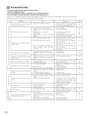
... securely. • Speaker cords not securely connected. • Improper position of the audio function button. • Volume control set to minimum. • MUTING is on. • Digital signals not input Digital input selected. • Speaker terminals are using headphones. • Mute mode is set... is cooled down . Once the set 's power, then ventilate it well to AVR-2803/983. • Ground wire of turntable not connected properly. • Incomplete PHONO jack connection. • TV or radio transmission antenna nearby. • Turntable and speaker systems too close together....
... securely. • Speaker cords not securely connected. • Improper position of the audio function button. • Volume control set to minimum. • MUTING is on. • Digital signals not input Digital input selected. • Speaker terminals are using headphones. • Mute mode is set... is cooled down . Once the set 's power, then ventilate it well to AVR-2803/983. • Ground wire of turntable not connected properly. • Incomplete PHONO jack connection. • TV or radio transmission antenna nearby. • Turntable and speaker systems too close together....
Owners Manual
Page 68
... ( ) but Dolby Pro Logic II they provide normal stereo sound. 68 Dolby Digital consists of up to 120 Hz). playback channels Playback channels (max.) Audio processing Dolby Digital 5.1 ch 5.1 ch L, R, C, SL, SR, SW Digital discrete processing Dolby Digital encoding/decoding Dolby Pro Logic 2 ch 4 ch L, R, C, S (SW ...to be used for the stereo broadcast signals of FM radio, TV, satellite broadcasts and cable TV. The following are equipped with both "bit stream + PCM" and "PCM only" digital outputs. Also refer to the AVR-2803/983. (2) Dolby Pro Logic II • Dolby Pro Logic ...
... ( ) but Dolby Pro Logic II they provide normal stereo sound. 68 Dolby Digital consists of up to 120 Hz). playback channels Playback channels (max.) Audio processing Dolby Digital 5.1 ch 5.1 ch L, R, C, SL, SR, SW Digital discrete processing Dolby Digital encoding/decoding Dolby Pro Logic 2 ch 4 ch L, R, C, S (SW ...to be used for the stereo broadcast signals of FM radio, TV, satellite broadcasts and cable TV. The following are equipped with both "bit stream + PCM" and "PCM only" digital outputs. Also refer to the AVR-2803/983. (2) Dolby Pro Logic II • Dolby Pro Logic ...

Owners Manual
Page 72
.... Set the Ext. In Subwoofer terminal playback level. AUX VCR-1 VCR-2 TAPE OPT1 OPT2 OPT3 OFF OFF OFF OPT4 DVD VDP TV DBS VCR-1 VCR-2 V. y Dolby Digital Setup Turn the audio compression on the remote control unit or main unit are received automatically and stored in order to obtain optimum effects. Set whether...
.... Set the Ext. In Subwoofer terminal playback level. AUX VCR-1 VCR-2 TAPE OPT1 OPT2 OPT3 OFF OFF OFF OPT4 DVD VDP TV DBS VCR-1 VCR-2 V. y Dolby Digital Setup Turn the audio compression on the remote control unit or main unit are received automatically and stored in order to obtain optimum effects. Set whether...


