

Literature/Product Sheet
Page 1
...-2/V-AUX, MONITOR 3 Composite Outputs VCR-1, VCR-2/V-AUX, MONITOR NEW MODEL I N F O R M AT I O N Dolby Digital and DTS A/V Receiver AVR-2801 TENTATIVE Outstanding surround sound and affordable price, with Dolby Digital and DTS decoding s Equal Power Discrete Power Amplifier Front 90 W + 90 W (8 ohms, 20Hz... Level Control s Binding Post Speaker Terminals for All Channels s Icon-based On-Screen Display s Personal Memory Plus s Multi-function Remote Controller s Frequency Synthesis Tuning • 40-Station AM/FM Random Preset Memory Tuning • Auto Preset Memory s Other Features ...
...-2/V-AUX, MONITOR 3 Composite Outputs VCR-1, VCR-2/V-AUX, MONITOR NEW MODEL I N F O R M AT I O N Dolby Digital and DTS A/V Receiver AVR-2801 TENTATIVE Outstanding surround sound and affordable price, with Dolby Digital and DTS decoding s Equal Power Discrete Power Amplifier Front 90 W + 90 W (8 ohms, 20Hz... Level Control s Binding Post Speaker Terminals for All Channels s Icon-based On-Screen Display s Personal Memory Plus s Multi-function Remote Controller s Frequency Synthesis Tuning • 40-Station AM/FM Random Preset Memory Tuning • Auto Preset Memory s Other Features ...

Owners Manual
Page 4
... the tuner or TV. • Set the antenna wires from the tuner or TV away from the actual set for choosing the DENON AVR-2801/981 Digital Surround A / V receiver. Always set the power switch to occur particularly when using this unit: • Moving the... America model only 1 e Service station list...........1 t R6P/AA batteries............2 y AM loop antenna 1 u FM indoor antenna...1 i FM antenna adaptor........1 r Remote control unit (RC-881 1 1 BEFORE USING Pay attention to provide superb surround sound listening with an immense array of features, we recommend that before you...
... the tuner or TV. • Set the antenna wires from the tuner or TV away from the actual set for choosing the DENON AVR-2801/981 Digital Surround A / V receiver. Always set the power switch to occur particularly when using this unit: • Moving the... America model only 1 e Service station list...........1 t R6P/AA batteries............2 y AM loop antenna 1 u FM indoor antenna...1 i FM antenna adaptor........1 r Remote control unit (RC-881 1 1 BEFORE USING Pay attention to provide superb surround sound listening with an immense array of features, we recommend that before you...

Owners Manual
Page 6
... between on the main unit, and when the power is used with MC cartridges directly. Connecting a turntable Connect the turntable's output cord to the AVR-2801/981's PHONO jacks, the L (left , right with right). • Insert the plugs securely. AC 120V 60HZ AC OUTLETS Turntable (MM cartridge...Connecting the DIGITAL jacks Use these outlets is turned on and off in conjunction with the POWER operation switch on and standby from the remote control unit. NOTE: Only use them near a power transformer will result in the generation of this unit's tape recording (CDR/TAPE ...
... between on the main unit, and when the power is used with MC cartridges directly. Connecting a turntable Connect the turntable's output cord to the AVR-2801/981's PHONO jacks, the L (left , right with right). • Insert the plugs securely. AC 120V 60HZ AC OUTLETS Turntable (MM cartridge...Connecting the DIGITAL jacks Use these outlets is turned on and off in conjunction with the POWER operation switch on and standby from the remote control unit. NOTE: Only use them near a power transformer will result in the generation of this unit's tape recording (CDR/TAPE ...

Owners Manual
Page 12
VOL button 36) !7 MASTER VOLUME control 33) !8 Master volume indicator (VOLUME LEVEL 33) !9 Display @0 INPUT indicators 33) @1 SIGNAL indicator 33) @2 Remote control sensor (REMOTE SENSOR 23) @3 Power indicator 31) @4 FUNCTION knob 32) @5 TUNING PRESET button 47) @6 SOURCE selector button 32) @7 REC SELECT button 35) 12 q Power ON/STANDBY switch ...
VOL button 36) !7 MASTER VOLUME control 33) !8 Master volume indicator (VOLUME LEVEL 33) !9 Display @0 INPUT indicators 33) @1 SIGNAL indicator 33) @2 Remote control sensor (REMOTE SENSOR 23) @3 Power indicator 31) @4 FUNCTION knob 32) @5 TUNING PRESET button 47) @6 SOURCE selector button 32) @7 REC SELECT button 35) 12 q Power ON/STANDBY switch ...

Owners Manual
Page 13
LEDs (indicators 28) SYSTEM CALL buttons 29) Input source selector buttons 32) ENGLISH Remote control signal transmitter 23) Power button 31) Tuner buttons 45) System buttons 24) SPEAKER select button 31) Surround buttons 24) INPUT MODE selector buttons 32) ... button 27) STATUS button 34) NOTE • The shaded buttons do not function with the AVR-2801/981. (Nothing happens when they are pressed.) The button indicated , however, can be used with the learning function. 13 Remote control unit • For details on the functions of these parts, refer to the pages given...
LEDs (indicators 28) SYSTEM CALL buttons 29) Input source selector buttons 32) ENGLISH Remote control signal transmitter 23) Power button 31) Tuner buttons 45) System buttons 24) SPEAKER select button 31) Surround buttons 24) INPUT MODE selector buttons 32) ... button 27) STATUS button 34) NOTE • The shaded buttons do not function with the AVR-2801/981. (Nothing happens when they are pressed.) The button indicated , however, can be used with the learning function. 13 Remote control unit • For details on the functions of these parts, refer to the pages given...
Owners Manual
Page 14
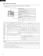
...remote control unit or main unit are received automatically and stored in your system and their Speaker corresponding sizes (SMALL for regular speakers, LARGE for full-size, q Configuration full-range) to 11), make the various settings described below on the monitor screen using the AVR-2801/...signals. SURROUND PARAMETER button Press this to display the surround parameter menu. LFE w Delay Time This parameter is connected to both the AVR-2801/981's S-Video and video monitor output jacks and signals are produced from the speakers and Front L Front R Subwoofer subwoofer for the...
...remote control unit or main unit are received automatically and stored in your system and their Speaker corresponding sizes (SMALL for regular speakers, LARGE for full-size, q Configuration full-range) to 11), make the various settings described below on the monitor screen using the AVR-2801/...signals. SURROUND PARAMETER button Press this to display the surround parameter menu. LFE w Delay Time This parameter is connected to both the AVR-2801/981's S-Video and video monitor output jacks and signals are produced from the speakers and Front L Front R Subwoofer subwoofer for the...
Owners Manual
Page 19
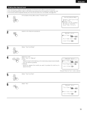
... is selected 6 Select "Yes". 19 ENGLISH 2 ENTER Switch to the test tones produced automatically from the different speakers. • Manual: Select the speaker from the remote control unit. (For details, see page 36.) 1 At the System Setup Menu select "Channel Level". Select "Auto" or "Manual". • Auto: Adjust the level while...
... is selected 6 Select "Yes". 19 ENGLISH 2 ENTER Switch to the test tones produced automatically from the different speakers. • Manual: Select the speaker from the remote control unit. (For details, see page 36.) 1 At the System Setup Menu select "Channel Level". Select "Auto" or "Manual". • Auto: Adjust the level while...

Owners Manual
Page 23
... devices as possible. 23 ENGLISH 8 REMOTE CONTROL UNIT • The included remote control unit (RC-881) can be used to operate not only the AVR-2801/981 but this depends on the diagram. • The remote control unit can be used to operate non-DENON remote control compatible video components. Using the remote control unit Approx. 7 m/22 feet...
... devices as possible. 23 ENGLISH 8 REMOTE CONTROL UNIT • The included remote control unit (RC-881) can be used to operate not only the AVR-2801/981 but this depends on the diagram. • The remote control unit can be used to operate non-DENON remote control compatible video components. Using the remote control unit Approx. 7 m/22 feet...

Owners Manual
Page 24
ENGLISH Operating DENON audio components • Turn on the power of components may not be operated with a wide range of infrared controlled components, some models of the different components before operating them. 1 Set mode switch 1 to "AUDIO (AVR/AVC)". CD ... and reverse) : Stop : Play : Auto search (cue) : Pause : Switch discs (for the component to the component's operating instructions. * While this remote control is compatible with this remote control. 1. up /down VOLUME DISC SKIP+ 6 : Rewind 7 : Fast-forward 2 : Stop 1 : Forward play 3 : Pause 0 : Reverse play...
ENGLISH Operating DENON audio components • Turn on the power of components may not be operated with a wide range of infrared controlled components, some models of the different components before operating them. 1 Set mode switch 1 to "AUDIO (AVR/AVC)". CD ... and reverse) : Stop : Play : Auto search (cue) : Pause : Switch discs (for the component to the component's operating instructions. * While this remote control is compatible with this remote control. 1. up /down VOLUME DISC SKIP+ 6 : Rewind 7 : Fast-forward 2 : Stop 1 : Forward play 3 : Pause 0 : Reverse play...

Owners Manual
Page 25
...A / B 3 The LEARNED/TX LED flashes. 1 Combinations of video component. In this case use the learning function (see page 28) to store the remote control signals. • For instructions on clearing the presettings stored in the preset memory, see page 31. 1 Set the slide switch to "VIDEO". IN)... ANALOG STEREO EXT.IN MASTER VOL. ENGLISH Preset memory (Audio component) • DENON components can be operated by setting the preset memory for the code in block B. (Refer to Table 1.) The operation is AVR/AVC VIDEO 2 Set the slide switch to the component to be registered (DVD,...
...A / B 3 The LEARNED/TX LED flashes. 1 Combinations of video component. In this case use the learning function (see page 28) to store the remote control signals. • For instructions on clearing the presettings stored in the preset memory, see page 31. 1 Set the slide switch to "VIDEO". IN)... ANALOG STEREO EXT.IN MASTER VOL. ENGLISH Preset memory (Audio component) • DENON components can be operated by setting the preset memory for the code in block B. (Refer to Table 1.) The operation is AVR/AVC VIDEO 2 Set the slide switch to the component to be registered (DVD,...

Owners Manual
Page 26
... -) ELECTRIC A - EXT.IN (EXT. If the component does not operate when set upon shipment from the factory. p - IN) DENON C - - - - CHANNEL CHANNEL GENERAL - (CHANNEL -) ELECTRIC A GENERAL ELECTRIC B - (A/B) NAGNAVOX A NAGNAVOX B NAGNAVOX C * Preset codes set to remote codeset A, try setting to clear the "learned" signals, do so as described on Table 1 cannot be used. •...
... -) ELECTRIC A - EXT.IN (EXT. If the component does not operate when set upon shipment from the factory. p - IN) DENON C - - - - CHANNEL CHANNEL GENERAL - (CHANNEL -) ELECTRIC A GENERAL ELECTRIC B - (A/B) NAGNAVOX A NAGNAVOX B NAGNAVOX C * Preset codes set to remote codeset A, try setting to clear the "learned" signals, do so as described on Table 1 cannot be used. •...

Owners Manual
Page 27
... T.TONE DVD SET UP 2 3 ENGLISH 3 Operate the video component. • For details, refer to be operated with this remote control unit. 1. Video disc player (VDP) system 3. AUDIO DECK CDR/MD CD MUTING AVR/AVC VIDEO TUNING DVD TV VDP VCR SYSTEM SETUP SURROUND PARAMETER BAND MODE MEMORY TITLE MENU/GUIDE CH SELECT...
... T.TONE DVD SET UP 2 3 ENGLISH 3 Operate the video component. • For details, refer to be operated with this remote control unit. 1. Video disc player (VDP) system 3. AUDIO DECK CDR/MD CD MUTING AVR/AVC VIDEO TUNING DVD TV VDP VCR SYSTEM SETUP SURROUND PARAMETER BAND MODE MEMORY TITLE MENU/GUIDE CH SELECT...

Owners Manual
Page 28
... LEARNED/TX LED does not light after the START LED lights, this unit's remote control unit. Light 7 To "learn " TV channels. ENGLISH Learning function • If your AV component is not a DENON product or it cannot be operated with the preset memory codesets, you have just...SELECT ENTER SELECT STATUS ON SCREEN DISPLAY RETURN USE/LEARN T.TONE DVD SET UP 3 B AVR/AVC VIDEO 5 Check that can "teach" the AVR-2801/981's remote control to "learn" the codes from the component's original remote control. • The buttons that the START LED is lit, then press the button...
... LEARNED/TX LED does not light after the START LED lights, this unit's remote control unit. Light 7 To "learn " TV channels. ENGLISH Learning function • If your AV component is not a DENON product or it cannot be operated with the preset memory codesets, you have just...SELECT ENTER SELECT STATUS ON SCREEN DISPLAY RETURN USE/LEARN T.TONE DVD SET UP 3 B AVR/AVC VIDEO 5 Check that can "teach" the AVR-2801/981's remote control to "learn" the codes from the component's original remote control. • The buttons that the START LED is lit, then press the button...

Owners Manual
Page 29
...have stored at any button on DVD player (DVD) playback LD player (VDP) playback Video (VCR) playback The system call signals for transmitting multiple remote control signals when a single button is pressed (this section. (See page 30.) Button No. CALL 2 Press the button at which the desired ...POWER OFF and POWER ON buttons are transmitted from the remote control unit approximately once every second. System call signals are already preset at the touch of up to as a "macro" function). AUDIO DECK CDR/MD CD MUTING AVR/AVC VIDEO TUNING DVD TV VDP VCR SYSTEM SETUP SURROUND...
...have stored at any button on DVD player (DVD) playback LD player (VDP) playback Video (VCR) playback The system call signals for transmitting multiple remote control signals when a single button is pressed (this section. (See page 30.) Button No. CALL 2 Press the button at which the desired ...POWER OFF and POWER ON buttons are transmitted from the remote control unit approximately once every second. System call signals are already preset at the touch of up to as a "macro" function). AUDIO DECK CDR/MD CD MUTING AVR/AVC VIDEO TUNING DVD TV VDP VCR SYSTEM SETUP SURROUND...

Owners Manual
Page 30
...SET UP 1 Press the SET button. • The START LED and LEARNED/TX LED both flash. AUDIO AVR/AVC VIDEO DECK CDR/MD CD DVD TV VDP VCR 2 Press the button whose remote control signals you want to store one by one. 5 Press the SET button. ENGLISH (3) Storing signals ...VOLUME DISC SKIP+ SPEAKER DOLBY / DTS SURROUND DIRECT DSP SIMULATION 5CH STEREO INPUT MODE ANALOG STEREO EXT.IN MASTER VOL. SET NOTES: • The remote control signals for the component whose settings you want to clear. 3 Press the SET button. • The button is reset to the settings shown on...
...SET UP 1 Press the SET button. • The START LED and LEARNED/TX LED both flash. AUDIO AVR/AVC VIDEO DECK CDR/MD CD DVD TV VDP VCR 2 Press the button whose remote control signals you want to store one by one. 5 Press the SET button. ENGLISH (3) Storing signals ...VOLUME DISC SKIP+ SPEAKER DOLBY / DTS SURROUND DIRECT DSP SIMULATION 5CH STEREO INPUT MODE ANALOG STEREO EXT.IN MASTER VOL. SET NOTES: • The remote control signals for the component whose settings you want to clear. 3 Press the SET button. • The button is reset to the settings shown on...

Owners Manual
Page 31
...with the tip of a pen, etc., to the position at which the signals were "learned". AUDIO AVR/AVC VIDEO 3 Set the slide switch to set the learn mode. 2 To clear "learned" remote control signals, set and the display turns off , the standby mode is still connected on AC line voltage.... Press the POWER switch (button). AUDIO DECK CDR/MD CD MUTING AVR/AVC VIDEO TUNING DVD TV VDP VCR SYSTEM SETUP SURROUND PARAMETER TITLE MENU/GUIDE (Main unit) (Remote control unit) 31 When pressed again, the power turns off . Press SPEAKER A or B turn ...
...with the tip of a pen, etc., to the position at which the signals were "learned". AUDIO AVR/AVC VIDEO 3 Set the slide switch to set the learn mode. 2 To clear "learned" remote control signals, set and the display turns off , the standby mode is still connected on AC line voltage.... Press the POWER switch (button). AUDIO DECK CDR/MD CD MUTING AVR/AVC VIDEO TUNING DVD TV VDP VCR SYSTEM SETUP SURROUND PARAMETER TITLE MENU/GUIDE (Main unit) (Remote control unit) 31 When pressed again, the power turns off . Press SPEAKER A or B turn ...

Owners Manual
Page 32
... from a laser disc player. • Noise may be selected for the selected input source are detected and the program in the AVR-2801/981's surround decoder is detected, the signals input to the digital input jacks are identified and decoding and playback are selected. If ... DTS signal playback mode) Decoding and playback are only performed when DTS signals are played without passing through the surround circuitry. ANALOG ANALOG (Main unit) (Remote control unit) • Selecting the external input (EXT. AUTO PCM DTS 1 START SYSTEM CALL SET CALL DVD VDP 1 2 TV/DBS 4 5 ...
... from a laser disc player. • Noise may be selected for the selected input source are detected and the program in the AVR-2801/981's surround decoder is detected, the signals input to the digital input jacks are identified and decoding and playback are selected. If ... DTS signal playback mode) Decoding and playback are only performed when DTS signals are played without passing through the surround circuitry. ANALOG ANALOG (Main unit) (Remote control unit) • Selecting the external input (EXT. AUTO PCM DTS 1 START SYSTEM CALL SET CALL DVD VDP 1 2 TV/DBS 4 5 ...

Owners Manual
Page 33
...within the range of -60 to 0 to +12 dB in steps of 1 dB. Example: Stereo SURROUND MODE SELECT STEREO (Main unit) (Remote control unit) * To select the surround mode while adjusting the surround parameters, channel volume or tone control, press the surround mode button then ...heard. The volume level is displayed on the master volume level display. (Main unit) (Remote control unit) * The volume can be increased to up to the component's manual. 5 Adjust the volume. B REMOTE SENSOR STAND BY LOCK AUTO SIGNAL DIGITAL INPUT DIGITAL PCM VOLUME LEVEL 21 (Main unit) ...
...within the range of -60 to 0 to +12 dB in steps of 1 dB. Example: Stereo SURROUND MODE SELECT STEREO (Main unit) (Remote control unit) * To select the surround mode while adjusting the surround parameters, channel volume or tone control, press the surround mode button then ...heard. The volume level is displayed on the master volume level display. (Main unit) (Remote control unit) * The volume can be increased to up to the component's manual. 5 Adjust the volume. B REMOTE SENSOR STAND BY LOCK AUTO SIGNAL DIGITAL INPUT DIGITAL PCM VOLUME LEVEL 21 (Main unit) ...

Owners Manual
Page 34
... * Cancelling simulcast playback. (Main unit) • Select "SOURCE" using headphones. [3] Turning the sound off . AUDIO DECK CDR/MD CD MUTING AVR/AVC VIDEO DVD TV VDP VCR 1 [4] Combining the currently playing sound with the desired image 1 Simulcast playback Use this to the unit's VIDEO MONITOR..., the display can be switched to the PHONES jack of that operation appears on the display connected to turn off ) by pressing the remote control unit's DIMMER button repeatedly. * The brightness changes in 3 steps each time the button is output in four steps (bright, medium...
... * Cancelling simulcast playback. (Main unit) • Select "SOURCE" using headphones. [3] Turning the sound off . AUDIO DECK CDR/MD CD MUTING AVR/AVC VIDEO DVD TV VDP VCR 1 [4] Combining the currently playing sound with the desired image 1 Simulcast playback Use this to the unit's VIDEO MONITOR..., the display can be switched to the PHONES jack of that operation appears on the display connected to turn off ) by pressing the remote control unit's DIMMER button repeatedly. * The brightness changes in 3 steps each time the button is output in four steps (bright, medium...

Owners Manual
Page 35
...AUTO, PCM, DTS) or ANALOG button to switch to the desired input mode. (See page 32.) INPUT MODE ANALOG INPUT MODE ANALOG (Main unit) (Remote control unit) • When the input mode is set . 2 VOLUME DISC SKIP+ SPEAKER DOLBY / DTS SURROUND DIRECT DSP SIMULATION 5CH STEREO INPUT MODE ..."REC OUT SOURCE" displayed, turn the function knob and select "SOURCE". EXT.IN EXT.IN Press the EXT. AUDIO DECK CDR/MD CD MUTING AVR/AVC VIDEO TUNING DVD TV VDP VCR SYSTEM SETUP SURROUND PARAMETER BAND MODE TITLE MENU/GUIDE CH SELECT ENTER SELECT 1 NOTES: • In play ...
...AUTO, PCM, DTS) or ANALOG button to switch to the desired input mode. (See page 32.) INPUT MODE ANALOG INPUT MODE ANALOG (Main unit) (Remote control unit) • When the input mode is set . 2 VOLUME DISC SKIP+ SPEAKER DOLBY / DTS SURROUND DIRECT DSP SIMULATION 5CH STEREO INPUT MODE ..."REC OUT SOURCE" displayed, turn the function knob and select "SOURCE". EXT.IN EXT.IN Press the EXT. AUDIO DECK CDR/MD CD MUTING AVR/AVC VIDEO TUNING DVD TV VDP VCR SYSTEM SETUP SURROUND PARAMETER BAND MODE TITLE MENU/GUIDE CH SELECT ENTER SELECT 1 NOTES: • In play ...


