

Literature/Product Sheet
Page 1
.../DBS, VCR-1, VCR-2/V-AUX, CDR/TAPE 6 Analog EXT. NEW MODEL I N F O R M AT I O N Dolby Digital and DTS A/V Receiver AVR-2801 TENTATIVE Outstanding surround sound and affordable price, with Dolby Digital and DTS decoding s Equal Power Discrete Power Amplifier Front 90 W + 90 W (8 ohms, 20Hz ...Discrete Surround Circuit-Digital) s Dolby Digital and DTS Decoder s Front (L,R) A/B Speaker Switching s 96kHz, 24-bit Audio D/A Converters s 6-Channel External Input For DVD-Audio and SACD s Separate Current Supplies for Circuits s Hefty Power Transformer for Stable Supply of Power s Stable Speaker ...
.../DBS, VCR-1, VCR-2/V-AUX, CDR/TAPE 6 Analog EXT. NEW MODEL I N F O R M AT I O N Dolby Digital and DTS A/V Receiver AVR-2801 TENTATIVE Outstanding surround sound and affordable price, with Dolby Digital and DTS decoding s Equal Power Discrete Power Amplifier Front 90 W + 90 W (8 ohms, 20Hz ...Discrete Surround Circuit-Digital) s Dolby Digital and DTS Decoder s Front (L,R) A/B Speaker Switching s 96kHz, 24-bit Audio D/A Converters s 6-Channel External Input For DVD-Audio and SACD s Separate Current Supplies for Circuits s Hefty Power Transformer for Stable Supply of Power s Stable Speaker ...

Owners Manual
Page 5
... digital processing algorithms, Dolby Digital provides up during this happens, either turn down the MASTER VOLUME control or connect components to 5.1 channels of this, the output signals are not connected A clicking noise may be produced if the input function is switched when nothing is... such as laser disc, DVD and specially-encoded music discs. 3. 24 bit D/A Conversion All six channels, including the five main channels and the low frequency effects (LFE) channel benefit from reference, for optimum high fidelity reproduction of PRE OUT jacks, HEADPHONE jack and SPEAKER terminals ...
... digital processing algorithms, Dolby Digital provides up during this happens, either turn down the MASTER VOLUME control or connect components to 5.1 channels of this, the output signals are not connected A clicking noise may be produced if the input function is switched when nothing is... such as laser disc, DVD and specially-encoded music discs. 3. 24 bit D/A Conversion All six channels, including the five main channels and the low frequency effects (LFE) channel benefit from reference, for optimum high fidelity reproduction of PRE OUT jacks, HEADPHONE jack and SPEAKER terminals ...

Owners Manual
Page 6
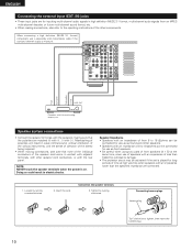
... left and right channels properly (left with right). • Insert the plugs securely. If this happens, turn on . The power to these jacks if you wish to connect external power amplifier(s) to the right jack. Connecting a turntable Connect the turntable's output cord to the AVR-2801/981's PHONO jacks.... If humming or other noise. • Noise or humming may be used independently without turning the power of the front, center and surround channels, or for hair driers, etc. • Note that they do not obstruct the ventilation holes. IN R L IN FR FL DVD LOOP...
... left and right channels properly (left with right). • Insert the plugs securely. If this happens, turn on . The power to these jacks if you wish to connect external power amplifier(s) to the right jack. Connecting a turntable Connect the turntable's output cord to the AVR-2801/981's PHONO jacks.... If humming or other noise. • Noise or humming may be used independently without turning the power of the front, center and surround channels, or for hair driers, etc. • Note that they do not obstruct the ventilation holes. IN R L IN FR FL DVD LOOP...
Owners Manual
Page 10
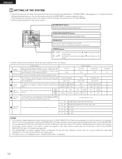
... in contact with adjacent terminals, with other components. Speaker Impedance • Speakers with an impedance of from an MPEG multi-channel decoder, or future multi-channel sound format, etc. • When making sure that none of the individual conductors of the speaker cord come in weak ... the various instruments, and the sense of direction of time at the same time, since use a separately sold mono/stereo cable if the surround channel output is monaural. IN R L IN FR FL DVD LLOOP ANT. Speaker system connections • Connect the speaker terminals with √ )....
... in contact with adjacent terminals, with other components. Speaker Impedance • Speakers with an impedance of from an MPEG multi-channel decoder, or future multi-channel sound format, etc. • When making sure that none of the individual conductors of the speaker cord come in weak ... the various instruments, and the sense of direction of time at the same time, since use a separately sold mono/stereo cable if the surround channel output is monaural. IN R L IN FR FL DVD LLOOP ANT. Speaker system connections • Connect the speaker terminals with √ )....

Owners Manual
Page 13
... volume control buttons 33) MUTING button 34) SURROUND PARAMETER button 41) Channel select/enter button 14) Cursor buttons 14) ON SCREEN button 34) DVD SETUP button 27) STATUS button 34) NOTE • The shaded buttons do not function with the AVR-2801/981. (Nothing happens when they are pressed.) The button indicated , however...
... volume control buttons 33) MUTING button 34) SURROUND PARAMETER button 41) Channel select/enter button 14) Cursor buttons 14) ON SCREEN button 34) DVD SETUP button 27) STATUS button 34) NOTE • The shaded buttons do not function with the AVR-2801/981. (Nothing happens when they are pressed.) The button indicated , however...
Owners Manual
Page 14
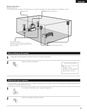
...), make the various settings described below on the monitor screen using the AVR-2801/981's on TVs with small screens or low resolutions. • The setup menu is not displayed when "HEADPHONE ONLY" is for the different channels in order to the left and right on the remote control unit or... main unit are received automatically and stored in "CONNECTIONS" (see page 22.) • The AVR-2801/981's on-screen display function is designed for playing deep bass...
...), make the various settings described below on the monitor screen using the AVR-2801/981's on TVs with small screens or low resolutions. • The setup menu is not displayed when "HEADPHONE ONLY" is for the different channels in order to the left and right on the remote control unit or... main unit are received automatically and stored in "CONNECTIONS" (see page 22.) • The AVR-2801/981's on-screen display function is designed for playing deep bass...
Owners Manual
Page 15
Setting the type of speakers • The composition of the signals output from the different channels and the frequency response are correct, then turn on the main unit's power. 2 SYSTEM SETUP TITLE Display the System Setup Menu. Surround speaker systems Before ...
Setting the type of speakers • The composition of the signals output from the different channels and the frequency response are correct, then turn on the main unit's power. 2 SYSTEM SETUP TITLE Display the System Setup Menu. Surround speaker systems Before ...
Owners Manual
Page 19
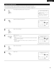
... from the different speakers. • Manual: Select the speaker from the remote control unit. (For details, see page 36.) 1 At the System Setup Menu select "Channel Level". Example: When the "Auto" mode is equal. • From the listening position, listen to the test tones produced from the speakers to adjust the... level can also be adjusted directly from which you want to produce the test tone to adjust the level. 5 Select "Test Tone Start". Setting the channel level • Use this setting to adjust so that the playback level between the different...
... from the different speakers. • Manual: Select the speaker from the remote control unit. (For details, see page 36.) 1 At the System Setup Menu select "Channel Level". Example: When the "Auto" mode is equal. • From the listening position, listen to the test tones produced from the speakers to adjust the... level can also be adjusted directly from which you want to produce the test tone to adjust the level. 5 Select "Test Tone Start". Setting the channel level • Use this setting to adjust so that the playback level between the different...

Owners Manual
Page 20
... need to adjust the subwoofer's own volume control. * When you want to the same volume. If a sound level meter is not available adjust the channels by ear is difficult, use the and cursor buttons to adjust so that the volume from the different speakers sounds the same. 8 ENTER Example: When... cursor buttons to -12 dB while the test tone is selected After the above settings are emitted from which you adjust the channel levels while in units of the AVR-2801/981 for just that will affect ALL surround modes. The test tones are completed, press the ENTER button. Example: When the...
... need to adjust the subwoofer's own volume control. * When you want to the same volume. If a sound level meter is not available adjust the channels by ear is difficult, use the and cursor buttons to adjust so that the volume from the different speakers sounds the same. 8 ENTER Example: When... cursor buttons to -12 dB while the test tone is selected After the above settings are emitted from which you adjust the channel levels while in units of the AVR-2801/981 for just that will affect ALL surround modes. The test tones are completed, press the ENTER button. Example: When the...

Owners Manual
Page 22
...Presets" from the "System Setup Menu" screen. 2 ENTER Press the ENTER button. NOTE: • If an FM station cannot be pressed at preset channels A1 to 8, B1 to 8, C1 to 8, D1 to 8 and E1 to 8. "Search" flashes on -screen display signals are output to the ... the SYSTEM SETUP button. * The changed settings are entered and the on-screen display turns off. • On-screen display signals Signals input to the AVR-2801/981 VIDEO signal input jack (yellow) S-video signal input jack 1 E E 2 C E 3 E C 4 C C (C: Signal E: No signal) On-screen display signal output VIDEO...
...Presets" from the "System Setup Menu" screen. 2 ENTER Press the ENTER button. NOTE: • If an FM station cannot be pressed at preset channels A1 to 8, B1 to 8, C1 to 8, D1 to 8 and E1 to 8. "Search" flashes on -screen display signals are output to the ... the SYSTEM SETUP button. * The changed settings are entered and the on-screen display turns off. • On-screen display signals Signals input to the AVR-2801/981 VIDEO signal input jack (yellow) S-video signal input jack 1 E E 2 C E 3 E C 4 C C (C: Signal E: No signal) On-screen display signal output VIDEO...

Owners Manual
Page 24
...DENON audio components • Turn on the power of components may not be operated with this remote control is compatible with a wide range of infrared controlled components, some models of the different components before operating them. 1 Set mode switch 1 to "AUDIO (AVR/AVC)". AUDIO DECK CDR/MD CD MUTING AVR...1 2 TV/DBS 4 5 VCR-1 CD 7 8 POWER OFF ON / SOURCE TUNER 3 PHONO 6 CDR / TAPE 9 SHIFT CHANNEL SHIFT : Switch preset channel range CHANNEL : Preset channel +, - Tape deck (DECK) system buttons VCR-2/V.AUX +10 TV/VCR A / B VOLUME DISC SKIP+ 6, 7 2 1 ...
...DENON audio components • Turn on the power of components may not be operated with this remote control is compatible with a wide range of infrared controlled components, some models of the different components before operating them. 1 Set mode switch 1 to "AUDIO (AVR/AVC)". AUDIO DECK CDR/MD CD MUTING AVR...1 2 TV/DBS 4 5 VCR-1 CD 7 8 POWER OFF ON / SOURCE TUNER 3 PHONO 6 CDR / TAPE 9 SHIFT CHANNEL SHIFT : Switch preset channel range CHANNEL : Preset channel +, - Tape deck (DECK) system buttons VCR-2/V.AUX +10 TV/VCR A / B VOLUME DISC SKIP+ 6, 7 2 1 ...

Owners Manual
Page 25
...7 8 VCR-2/V.AUX +10 0 RC-881 LEARNED/TX POWER OFF ON / SOURCE TUNER 3 SHIFT PHONO 6 CDR / TAPE 9 CHANNEL TV/VCR A / B 3,4 3 DVD TV VDP VCR ( ) Keep the POWER button pressed in when performing steps 3 and ... 5CH STEREO INPUT MODE ANALOG STEREO EXT.IN MASTER VOL. IN) (POWER) ON/SOURCE DENON CDR A DENON CDR B DENON MD * Preset codes set . Operation is not possible for the code in the preset ... STEREO INPUT MODE ANALOG STEREO EXT.IN MASTER VOL. AUDIO DECK CDR/MD CD MUTING AVR/AVC VIDEO TUNING DVD TV VDP VCR SYSTEM SETUP SURROUND PARAMETER 3 2 DIRECT STEREO EXT...
...7 8 VCR-2/V.AUX +10 0 RC-881 LEARNED/TX POWER OFF ON / SOURCE TUNER 3 SHIFT PHONO 6 CDR / TAPE 9 CHANNEL TV/VCR A / B 3,4 3 DVD TV VDP VCR ( ) Keep the POWER button pressed in when performing steps 3 and ... 5CH STEREO INPUT MODE ANALOG STEREO EXT.IN MASTER VOL. IN) (POWER) ON/SOURCE DENON CDR A DENON CDR B DENON MD * Preset codes set . Operation is not possible for the code in the preset ... STEREO INPUT MODE ANALOG STEREO EXT.IN MASTER VOL. AUDIO DECK CDR/MD CD MUTING AVR/AVC VIDEO TUNING DVD TV VDP VCR SYSTEM SETUP SURROUND PARAMETER 3 2 DIRECT STEREO EXT...

Owners Manual
Page 26
... A (DIRECT) (STEREO) q (DVD) - - e (TUNER) MITSUBISHI A MITSUBISHI B r (TV/DBS) PANASONIC A PANASONIC B t JVC (VICTOR) - STEREO (STEREO) DENON B EXT.IN (EXT. w (VDP) DENON/HITACHI - y (PHONO) SONY - y (PHONO) SONY u (VCR-1) PIONEER i (CD) TOSHIBA o (CDR/TAPE) - (VCR/V.AUX) - SHIFT (SHIFT) PHILIPS A - + (CHANNEL +) RCA A CHANNEL CHANNEL GENERAL - (CHANNEL -) ELECTRIC A - e (TUNER) - p - To avoid accidental operation, cover the remote control unit's transmitting window while...
... A (DIRECT) (STEREO) q (DVD) - - e (TUNER) MITSUBISHI A MITSUBISHI B r (TV/DBS) PANASONIC A PANASONIC B t JVC (VICTOR) - STEREO (STEREO) DENON B EXT.IN (EXT. w (VDP) DENON/HITACHI - y (PHONO) SONY - y (PHONO) SONY u (VCR-1) PIONEER i (CD) TOSHIBA o (CDR/TAPE) - (VCR/V.AUX) - SHIFT (SHIFT) PHILIPS A - + (CHANNEL +) RCA A CHANNEL CHANNEL GENERAL - (CHANNEL -) ELECTRIC A - e (TUNER) - p - To avoid accidental operation, cover the remote control unit's transmitting window while...

Owners Manual
Page 27
...) (forward and reverse) •,ª up /down 2 : Stop 2 : Stop TV/VCR : Switch between TV 1 : Play 1 : Play and VCR 8,9 : Auto search (cue) 3 : Pause CHANNEL : Switch channel 3 : Pause CHANNEL : Switch channel +, - +, - 27 AUDIO AVR/AVC VIDEO 2 Set the slide switch to the component to the component's operating instructions. * Some models cannot be registered (DVD, VDP, VCR or...
...) (forward and reverse) •,ª up /down 2 : Stop 2 : Stop TV/VCR : Switch between TV 1 : Play 1 : Play and VCR 8,9 : Auto search (cue) 3 : Pause CHANNEL : Switch channel 3 : Pause CHANNEL : Switch channel +, - +, - 27 AUDIO AVR/AVC VIDEO 2 Set the slide switch to the component to the component's operating instructions. * Some models cannot be registered (DVD, VDP, VCR or...

Owners Manual
Page 28
... stops flashing and the START LED lights. Flashes A TV/DBS PHONO 4 5 6 VCR-1 7 CD CDR / TAPE CHANNEL 8 9 VCR-2/V.AUX +10 0 TV/VCR A / B 4 This unit's remote control unit 2 Set the program switch... other remote control unit. ENGLISH Learning function • If your AV component is not a DENON product or it cannot be operated with the preset memory codesets, you have just attempted to ...this means that the memory is already full, and the code you can "teach" the AVR-2801/981's remote control to "learn" the codes from the component's original remote control. •...
... stops flashing and the START LED lights. Flashes A TV/DBS PHONO 4 5 6 VCR-1 7 CD CDR / TAPE CHANNEL 8 9 VCR-2/V.AUX +10 0 TV/VCR A / B 4 This unit's remote control unit 2 Set the program switch... other remote control unit. ENGLISH Learning function • If your AV component is not a DENON product or it cannot be operated with the preset memory codesets, you have just attempted to ...this means that the memory is already full, and the code you can "teach" the AVR-2801/981's remote control to "learn" the codes from the component's original remote control. •...

Owners Manual
Page 29
... 1 2 TV/DBS 4 5 VCR-1 CD 7 8 VCR-2/V.AUX +10 0 RC-881 LEARNED/TX POWER OFF ON / SOURCE TUNER 3 SHIFT PHONO 6 CDR / TAPE 9 CHANNEL TV/VCR A / B 1 VOLUME DISC SKIP+ SPEAKER DOLBY / DTS SURROUND DIRECT DSP SIMULATION 5CH STEREO INPUT MODE ANALOG STEREO EXT.IN MASTER VOL. System call signals..., select the input source, turn on the monitor TV's power, turn on the table below. AUDIO DECK CDR/MD CD MUTING AVR/AVC VIDEO TUNING DVD TV VDP VCR SYSTEM SETUP SURROUND PARAMETER BAND MODE MEMORY TITLE MENU/GUIDE CH SELECT ENTER SELECT STATUS ON SCREEN...
... 1 2 TV/DBS 4 5 VCR-1 CD 7 8 VCR-2/V.AUX +10 0 RC-881 LEARNED/TX POWER OFF ON / SOURCE TUNER 3 SHIFT PHONO 6 CDR / TAPE 9 CHANNEL TV/VCR A / B 1 VOLUME DISC SKIP+ SPEAKER DOLBY / DTS SURROUND DIRECT DSP SIMULATION 5CH STEREO INPUT MODE ANALOG STEREO EXT.IN MASTER VOL. System call signals..., select the input source, turn on the monitor TV's power, turn on the table below. AUDIO DECK CDR/MD CD MUTING AVR/AVC VIDEO TUNING DVD TV VDP VCR SYSTEM SETUP SURROUND PARAMETER BAND MODE MEMORY TITLE MENU/GUIDE CH SELECT ENTER SELECT STATUS ON SCREEN...

Owners Manual
Page 30
...2 TV/DBS 4 5 VCR-1 CD 7 8 VCR-2/V.AUX +10 0 RC-881 LEARNED/TX POWER OFF ON / SOURCE TUNER 3 SHIFT PHONO 6 CDR / TAPE 9 CHANNEL TV/VCR A / B VOLUME DISC SKIP+ SPEAKER DOLBY / DTS SURROUND DIRECT DSP SIMULATION 5CH STEREO INPUT MODE ANALOG STEREO EXT.IN MASTER VOL. AUDIO DECK CDR.../MD CD MUTING AVR/AVC VIDEO TUNING DVD TV VDP VCR SYSTEM SETUP SURROUND PARAMETER BAND MODE MEMORY TITLE MENU/GUIDE CH SELECT ENTER SELECT STATUS ON...
...2 TV/DBS 4 5 VCR-1 CD 7 8 VCR-2/V.AUX +10 0 RC-881 LEARNED/TX POWER OFF ON / SOURCE TUNER 3 SHIFT PHONO 6 CDR / TAPE 9 CHANNEL TV/VCR A / B VOLUME DISC SKIP+ SPEAKER DOLBY / DTS SURROUND DIRECT DSP SIMULATION 5CH STEREO INPUT MODE ANALOG STEREO EXT.IN MASTER VOL. AUDIO DECK CDR.../MD CD MUTING AVR/AVC VIDEO TUNING DVD TV VDP VCR SYSTEM SETUP SURROUND PARAMETER BAND MODE MEMORY TITLE MENU/GUIDE CH SELECT ENTER SELECT STATUS ON...

Owners Manual
Page 31
...the display turns off. Whenever the ON/STANDBY button is still connected on AC line voltage. AUDIO DECK CDR/MD CD MUTING AVR/AVC VIDEO TUNING DVD TV VDP VCR SYSTEM SETUP SURROUND PARAMETER BAND MODE MEMORY TITLE MENU/GUIDE CH SELECT ENTER SELECT STATUS ON...1 2 TV/DBS 4 5 VCR-1 CD 7 8 VCR-2/V.AUX +10 0 RC-881 LEARNED/TX POWER OFF ON / SOURCE TUNER 3 SHIFT PHONO 6 CDR / TAPE 9 CHANNEL TV/VCR A / B 4 2 1,5 VOLUME DISC SKIP+ SPEAKER DOLBY / DTS SURROUND DIRECT DSP SIMULATION 5CH STEREO INPUT MODE ANALOG STEREO EXT.IN MASTER VOL. ENGLISH Clearing "...
...the display turns off. Whenever the ON/STANDBY button is still connected on AC line voltage. AUDIO DECK CDR/MD CD MUTING AVR/AVC VIDEO TUNING DVD TV VDP VCR SYSTEM SETUP SURROUND PARAMETER BAND MODE MEMORY TITLE MENU/GUIDE CH SELECT ENTER SELECT STATUS ON...1 2 TV/DBS 4 5 VCR-1 CD 7 8 VCR-2/V.AUX +10 0 RC-881 LEARNED/TX POWER OFF ON / SOURCE TUNER 3 SHIFT PHONO 6 CDR / TAPE 9 CHANNEL TV/VCR A / B 4 2 1,5 VOLUME DISC SKIP+ SPEAKER DOLBY / DTS SURROUND DIRECT DSP SIMULATION 5CH STEREO INPUT MODE ANALOG STEREO EXT.IN MASTER VOL. ENGLISH Clearing "...

Owners Manual
Page 32
...2 TV/DBS 4 5 VCR-1 CD 7 8 VCR-2/V.AUX +10 0 RC-881 LEARNED/TX POWER OFF ON / SOURCE TUNER 3 SHIFT PHONO 6 CDR / TAPE 9 CHANNEL TV/VCR A / B 3 2 VOLUME DISC SKIP+ SPEAKER DOLBY / DTS SURROUND DIRECT DSP SIMULATION 5CH STEREO INPUT MODE ANALOG STEREO EXT.IN MASTER VOL. r ANALOG (...jacks are selected. NOTES: • Note that noise will be output when CDs or LDs recorded in DTS format are played in the AVR-2801/981's surround decoder is selected automatically upon playback. INPUT MODE INPUT MODE 32 (Main unit) (Remote control unit) e DTS (exclusive ...
...2 TV/DBS 4 5 VCR-1 CD 7 8 VCR-2/V.AUX +10 0 RC-881 LEARNED/TX POWER OFF ON / SOURCE TUNER 3 SHIFT PHONO 6 CDR / TAPE 9 CHANNEL TV/VCR A / B 3 2 VOLUME DISC SKIP+ SPEAKER DOLBY / DTS SURROUND DIRECT DSP SIMULATION 5CH STEREO INPUT MODE ANALOG STEREO EXT.IN MASTER VOL. r ANALOG (...jacks are selected. NOTES: • Note that noise will be output when CDs or LDs recorded in DTS format are played in the AVR-2801/981's surround decoder is selected automatically upon playback. INPUT MODE INPUT MODE 32 (Main unit) (Remote control unit) e DTS (exclusive ...

Owners Manual
Page 33
...whether the digital input component setup (page 21) and connections are correct and whether the component's power is pressed. However, when the channel level is set as follows each time the TONE CONTROL button is turned on the master volume level display. (Main unit) (Remote ... Example: Stereo SURROUND MODE SELECT STEREO (Main unit) (Remote control unit) * To select the surround mode while adjusting the surround parameters, channel volume or tone control, press the surround mode button then operate the selector. ENGLISH 3 Select the play mode. NOTE: • The digital...
...whether the digital input component setup (page 21) and connections are correct and whether the component's power is pressed. However, when the channel level is set as follows each time the TONE CONTROL button is turned on the master volume level display. (Main unit) (Remote ... Example: Stereo SURROUND MODE SELECT STEREO (Main unit) (Remote control unit) * To select the surround mode while adjusting the surround parameters, channel volume or tone control, press the surround mode button then operate the selector. ENGLISH 3 Select the play mode. NOTE: • The digital...


