
Literature/Product Sheet
Page 1
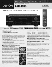
... Rectifier design uses two rectifying diodes in a design that program. s Acclaimed Customization Feature As with all of DENON's high-grade A/V receivers, the AVR-1905 lets you adjust delay times and other parameters so that is placed in parallel to the demands of the audio...to give you more clearly defined sound localization at low impedance, they are not required. s Dual-Channel Surround Back Power Amps for 7.1 Surround The AVR-1905 is too strong. The AVR-1905 inherits this sound is housed inside a highly rigid frame to secure it more faithful reproduction of the original ...
... Rectifier design uses two rectifying diodes in a design that program. s Acclaimed Customization Feature As with all of DENON's high-grade A/V receivers, the AVR-1905 lets you adjust delay times and other parameters so that is placed in parallel to the demands of the audio...to give you more clearly defined sound localization at low impedance, they are not required. s Dual-Channel Surround Back Power Amps for 7.1 Surround The AVR-1905 is too strong. The AVR-1905 inherits this sound is housed inside a highly rigid frame to secure it more faithful reproduction of the original ...
Literature/Product Sheet
Page 2
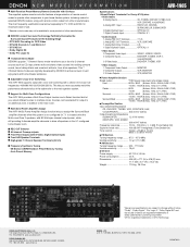
s Multi Zone Power Amplifier Assign The AVR-1905's Power Amplifier Assign function lets you assign the Surround Back amplifier channels when the system is registered trademarks of DTS Technology. DENON, LTD. 3-16-11, YUSHIMA, BUNKYO-KU, TOKYO 113-0034, JAPAN 13530704 A s REC OUT Selector s All channel Preamp outputs s Front Panel Inputs (with 80 Watts per...
s Multi Zone Power Amplifier Assign The AVR-1905's Power Amplifier Assign function lets you assign the Surround Back amplifier channels when the system is registered trademarks of DTS Technology. DENON, LTD. 3-16-11, YUSHIMA, BUNKYO-KU, TOKYO 113-0034, JAPAN 13530704 A s REC OUT Selector s All channel Preamp outputs s Front Panel Inputs (with 80 Watts per...
Owners Manual
Page 4
... proceeding. Remote Control Unit 31 ~ 35 ⁄0 Operation 36 ~ 41 ⁄1 Multi Zone 42 ~ 44 ⁄2 Surround 45 ~ 53 ⁄3 DSP Surround Simulation 54 ~ 57 ⁄4 Listening to the Radio 58 ~ 61 ⁄5 Last Function Memory 61 ⁄6 Initialization of... outstanding high fidelity reproduction of features, we recommend that before you for choosing the DENON AVR-1905/785 Digital A / V Surround Receiver. This remarkable component has been engineered to provide superb surround sound listening with an immense array of your favorite music sources. TABLE OF CONTENTS ...
... proceeding. Remote Control Unit 31 ~ 35 ⁄0 Operation 36 ~ 41 ⁄1 Multi Zone 42 ~ 44 ⁄2 Surround 45 ~ 53 ⁄3 DSP Surround Simulation 54 ~ 57 ⁄4 Listening to the Radio 58 ~ 61 ⁄5 Last Function Memory 61 ⁄6 Initialization of... outstanding high fidelity reproduction of features, we recommend that before you for choosing the DENON AVR-1905/785 Digital A / V Surround Receiver. This remarkable component has been engineered to provide superb surround sound listening with an immense array of your favorite music sources. TABLE OF CONTENTS ...
Owners Manual
Page 5
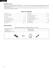
...the input function is switched when nothing is equipped with a V. Please be very high after the power switch is turned on or input function, surround mode or any other electronic equipment using microprocessors is changed. For heat dispersal, leave at least 4 inch/10 cm of space between all other ... connection cords. • Noise or disturbance tends to occur particularly when using indoor antennas or 300 Ω/ohms feeder wires. AUX terminal The AVR-1905/785's front panel is connected to the input jacks. We recommend using outdoor antennas and 75 Ω/ohms coaxial cables.
...the input function is switched when nothing is equipped with a V. Please be very high after the power switch is turned on or input function, surround mode or any other electronic equipment using microprocessors is changed. For heat dispersal, leave at least 4 inch/10 cm of space between all other ... connection cords. • Noise or disturbance tends to occur particularly when using indoor antennas or 300 Ω/ohms feeder wires. AUX terminal The AVR-1905/785's front panel is connected to the input jacks. We recommend using outdoor antennas and 75 Ω/ohms coaxial cables.
Owners Manual
Page 6
... one set simply by Digital Theater Systems Inc. DTS-ES Extended Surround and DTS Neo:6 The AVR-1905/785 can only be decoded with a set of cables offering a higher quality connection, regardless of this, the AVR-1905/785's MONITOR OUT jack can thus be connected to the listening room...developed by the 8 channel master volume control. The mode can be decoded with DTS Neo:6, a surround mode allowing 6.1 channels playback of wide-range, high fidelity surround sound. The AVR-1905/785 can be played in the multi-channel mode on the monitor screen according to the monitor (TV...
... one set simply by Digital Theater Systems Inc. DTS-ES Extended Surround and DTS Neo:6 The AVR-1905/785 can only be decoded with a set of cables offering a higher quality connection, regardless of this, the AVR-1905/785's MONITOR OUT jack can thus be connected to the listening room...developed by the 8 channel master volume control. The mode can be decoded with DTS Neo:6, a surround mode allowing 6.1 channels playback of wide-range, high fidelity surround sound. The AVR-1905/785 can be played in the multi-channel mode on the monitor screen according to the monitor (TV...

Owners Manual
Page 7
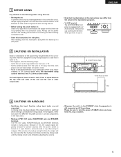
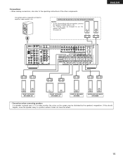
...8226; Noise or humming may be generated if a connected audio equipment is used independently without turning the power of the front, center and surround sound channels, or for audio equipment only. CD player DIGITAL AUDIO OUTPUT RL RL Connecting a CD player Connect the CD player's analog output...When making connections, also refer to the operating instructions of noise. • Use the AC OUTLETS for connection to SURR. NOTE: Only use Surround back with right). • Insert the plugs securely. Never use them near a power transformer will result in the AC cord until all ...
...8226; Noise or humming may be generated if a connected audio equipment is used independently without turning the power of the front, center and surround sound channels, or for audio equipment only. CD player DIGITAL AUDIO OUTPUT RL RL Connecting a CD player Connect the CD player's analog output...When making connections, also refer to the operating instructions of noise. • Use the AC OUTLETS for connection to SURR. NOTE: Only use Surround back with right). • Insert the plugs securely. Never use them near a power transformer will result in the AC cord until all ...
Owners Manual
Page 12
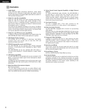
... outboard decoder, or a component with 6-channel analog output For instructions on playback using a 75 Ω/ohms video signal cable cord. AUX INPUT jacks. 12 R L R L Front Surround Subwoofer Center Decoder with a different type of multi-channel decoder, such as a DVD Audio player, a multi-channel SACD player, or other future multi-channel sound...
... outboard decoder, or a component with 6-channel analog output For instructions on playback using a 75 Ω/ohms video signal cable cord. AUX INPUT jacks. 12 R L R L Front Surround Subwoofer Center Decoder with a different type of multi-channel decoder, such as a DVD Audio player, a multi-channel SACD player, or other future multi-channel sound...
Owners Manual
Page 13
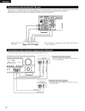
... amplifier or pre-main (integrated) amplifier is connected, the ZONE2 output terminals can be used to use this case , Surround Back Speaker OUT cannot be used for MAIN ZONE. (See page 29) SURROUND BACK/MULTI ZONE SPEAKER SYSTEMS NOTE: • The settings must be used when "ZONE2" is selected at System Setup...
... amplifier or pre-main (integrated) amplifier is connected, the ZONE2 output terminals can be used to use this case , Surround Back Speaker OUT cannot be used for MAIN ZONE. (See page 29) SURROUND BACK/MULTI ZONE SPEAKER SYSTEMS NOTE: • The settings must be used when "ZONE2" is selected at System Setup...
Owners Manual
Page 14
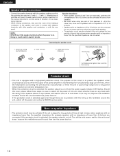
...protection circuit. When the protection circuit is activated, the speaker output is to protect the speakers under circumstances such as center and surround and surround back speakers. • The protector circuit may be connected for long periods of the power amplifier is inadvertently short-circuited and a... specified impedance (for the unit to cool down , improve the ventilation around the unit, switch off the power and contact a DENON service center. Improve the ventilation condition around the unit and switch the power back on speaker impedance • The protector circuit may...
...protection circuit. When the protection circuit is activated, the speaker output is to protect the speakers under circumstances such as center and surround and surround back speakers. • The protector circuit may be connected for long periods of the power amplifier is inadvertently short-circuited and a... specified impedance (for the unit to cool down , improve the ventilation around the unit, switch off the power and contact a DENON service center. Improve the ventilation condition around the unit and switch the power back on speaker impedance • The protector circuit may...
Owners Manual
Page 15
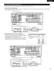
... to the operating instructions of the other components. If this speaker for subwoofer with one speaker, connect the speaker to use Surround back with built-in amplifier (super woofer), etc. Connection jack for ZONE2. BACK L CH. • The settings must... the speaker's magnetism. See page 29. (L) (R) ENGLISH (L) (R) FRONT SPEAKER SYSTEMS (B) (L) (R) FRONT SPEAKER SYSTEMS (A) CENTER SPEAKER SYSTEM (L) (R) SURROUND SPEAKER SYSTEMS • Precautions when connecting speakers If a speaker is placed near a TV or video monitor, the colors on the screen may be changed ...
... to the operating instructions of the other components. If this speaker for subwoofer with one speaker, connect the speaker to use Surround back with built-in amplifier (super woofer), etc. Connection jack for ZONE2. BACK L CH. • The settings must... the speaker's magnetism. See page 29. (L) (R) ENGLISH (L) (R) FRONT SPEAKER SYSTEMS (B) (L) (R) FRONT SPEAKER SYSTEMS (A) CENTER SPEAKER SYSTEM (L) (R) SURROUND SPEAKER SYSTEMS • Precautions when connecting speakers If a speaker is placed near a TV or video monitor, the colors on the screen may be changed ...
Owners Manual
Page 16
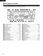
AUX INPUT terminals 5, 12) !6 SURROUND MODE button 38) !7 SURROUND PARAMETER button 47, 55) !8 SELECT knob 38, 48, 56) !9 TONE DEFEAT button 40) @0 TONE CONTROL button 40) @1 MASTER VOLUME control 38) @2 STATUS button 41) @3 DIMMER ... switch 21, 36, 58) w Power indicator 21, 36) e Power switch 21, 36) r Headphones jack (PHONES 40) t INPUT MODE button 37, 39) y SPEAKER A/B buttons 36, 61) u SURROUND BACK button 51) i EXT.
AUX INPUT terminals 5, 12) !6 SURROUND MODE button 38) !7 SURROUND PARAMETER button 47, 55) !8 SELECT knob 38, 48, 56) !9 TONE DEFEAT button 40) @0 TONE CONTROL button 40) @1 MASTER VOLUME control 38) @2 STATUS button 41) @3 DIMMER ... switch 21, 36, 58) w Power indicator 21, 36) e Power switch 21, 36) r Headphones jack (PHONES 40) t INPUT MODE button 37, 39) y SPEAKER A/B buttons 36, 61) u SURROUND BACK button 51) i EXT.
Owners Manual
Page 17
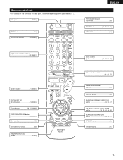
LED (indicator 32, 35) ZONE2 buttons 44) SURROUND buttons 38, 45, 55) ENGLISH Remote control signal transmitter 18) POWER buttons 21, 32~34, 36) MAIN buttons 44) Input source selector buttons 32~35, ..., 34, 59) Mode selector switches 31~33, 35) Master volume control buttons 38) MUTING button 40) SURROUND PARAMETER/SYSTEM button 33, 34, 47) CH SELECT (channel select)/ ENTER button 19, 33, 34, 46, 48) SURROUND BACK/RETURN button 33, 34, 51) SPEAKER button 36) DIMMER button 41) 17 Remote control unit •...
LED (indicator 32, 35) ZONE2 buttons 44) SURROUND buttons 38, 45, 55) ENGLISH Remote control signal transmitter 18) POWER buttons 21, 32~34, 36) MAIN buttons 44) Input source selector buttons 32~35, ..., 34, 59) Mode selector switches 31~33, 35) Master volume control buttons 38) MUTING button 40) SURROUND PARAMETER/SYSTEM button 33, 34, 47) CH SELECT (channel select)/ ENTER button 19, 33, 34, 46, 48) SURROUND BACK/RETURN button 33, 34, 51) SPEAKER button 36) DIMMER button 41) 17 Remote control unit •...
Owners Manual
Page 19
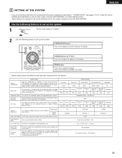
Set the frequency (Hz) below on the monitor screen using the AVR-1905/785's on the display. Surround Back Sp. CD COAXIAL DVD/VDP OPTICAL 1 AUTO Auto Surround Mode = ON TV/DBS OPTICAL 2 Ext. In SW Level Set the Ext. Use the following buttons to set up the system ... AV system centered around the AVR-1905/785. Input source Digital Inputs Video Input Mode Set the input signal to be output from the subwoofer. Large Front L Front R 12 ft 12 ft Front L Front R 0 dB 0 dB Center Sp. Auto Surround Mode Auto surround mode function setting. Surround Back On Screen Display =...
Set the frequency (Hz) below on the monitor screen using the AVR-1905/785's on the display. Surround Back Sp. CD COAXIAL DVD/VDP OPTICAL 1 AUTO Auto Surround Mode = ON TV/DBS OPTICAL 2 Ext. In SW Level Set the Ext. Use the following buttons to set up the system ... AV system centered around the AVR-1905/785. Input source Digital Inputs Video Input Mode Set the input signal to be output from the subwoofer. Large Front L Front R 12 ft 12 ft Front L Front R 0 dB 0 dB Center Sp. Auto Surround Mode Auto surround mode function setting. Surround Back On Screen Display =...
Owners Manual
Page 20
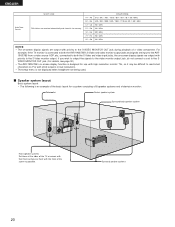
...Set these at the sides of a video component. Surround speaker systems 20 If you wish to output the signals to the video monitor output jack, do not connect a cord to the SVIDEO MONITOR OUT jack. (For details, see page 30.) • The AVR-1905/785's on-screen display function is not displayed when... jack during playback of the TV or screen with their front surfaces as possible. For example, if the TV monitor is connected to both the AVR-1905/785's S-Video and video monitor output jacks and signals are input to the AVR1905/785 from a video source (VDP, etc.) connected to both the ...
...Set these at the sides of a video component. Surround speaker systems 20 If you wish to output the signals to the video monitor output jack, do not connect a cord to the SVIDEO MONITOR OUT jack. (For details, see page 30.) • The AVR-1905/785's on-screen display function is not displayed when... jack during playback of the TV or screen with their front surfaces as possible. For example, if the TV monitor is connected to both the AVR-1905/785's S-Video and video monitor output jacks and signals are input to the AVR1905/785 from a video source (VDP, etc.) connected to both the ...

Owners Manual
Page 22
...Set whether or not speakers are adjusted automatically according to be achieved even when "Small" is set for the front, center and surround speakers. 22 Surround Sp. When this is set, bass sound with a frequency below the frequency set for the Crossover Frequency mode is not installed. ...channels and the frequency response are connected and, if so, their size parameters. Front Sp. • To select the speaker Subwoofer Listening position Surround Sp. Yes/No Select "Yes" when a subwoofer is installed, "No" when a subwoofer is sent to the SPEAKER DISTANCE • ...
...Set whether or not speakers are adjusted automatically according to be achieved even when "Small" is set for the front, center and surround speakers. 22 Surround Sp. When this is set, bass sound with a frequency below the frequency set for the Crossover Frequency mode is not installed. ...channels and the frequency response are connected and, if so, their size parameters. Front Sp. • To select the speaker Subwoofer Listening position Surround Sp. Yes/No Select "Yes" when a subwoofer is installed, "No" when a subwoofer is sent to the SPEAKER DISTANCE • ...

Owners Manual
Page 23
...: Distance between center speaker and listening position L2: Distance between front speakers and listening position L3: Distance between surround speakers and listening position L4: Distance between surround back speaker and listening position L5: Distance between the listening position and the different speakers to set . 7... and listening position CAUTION: Please note that the difference for every speaker should be set the delay time for the surround mode. Preparations: Measure the distances between the speaker and listening position. FL Center FR Subwoofer L1 L2 L5 Listening position...
...: Distance between center speaker and listening position L2: Distance between front speakers and listening position L3: Distance between surround speakers and listening position L4: Distance between surround back speaker and listening position L5: Distance between the listening position and the different speakers to set . 7... and listening position CAUTION: Please note that the difference for every speaker should be set the delay time for the surround mode. Preparations: Measure the distances between the speaker and listening position. FL Center FR Subwoofer L1 L2 L5 Listening position...

Owners Manual
Page 24
... channels and the subwoofer channel. Assignment of the room, interference may improve frequency response for the subwoofer in surround modes other than Dolby/DTS. • In surround modes other than Dolby Digital and DTS, if the subwoofer is set to "Small", sound with quantity. ...the cut bass sound is always output to the subwoofer channel. NOTE: For ordinary speaker systems, we recommend setting the crossover frequency to "Surround Modes and Parameters" on the size and shape of low frequency signal range - • The signals produced from the subwoofer instead. Subwoofer...
... channels and the subwoofer channel. Assignment of the room, interference may improve frequency response for the subwoofer in surround modes other than Dolby/DTS. • In surround modes other than Dolby Digital and DTS, if the subwoofer is set to "Small", sound with quantity. ...the cut bass sound is always output to the subwoofer channel. NOTE: For ordinary speaker systems, we recommend setting the crossover frequency to "Surround Modes and Parameters" on the size and shape of low frequency signal range - • The signals produced from the subwoofer instead. Subwoofer...

Owners Manual
Page 25
Setting the Test Tone • Use this setting to adjust to that the playback level between the different channel is equal. • From the listening position, listen to the test tones produced from the speakers to adjust the level. • The level can also be adjusted directly from the remote control unit. (For details, see page 45.) 1 • Use the (left) button to the Test Tone. • Press the ENTER or Assignment. (down) button to switch to the Digital In 17 T.TONE
Setting the Test Tone • Use this setting to adjust to that the playback level between the different channel is equal. • From the listening position, listen to the test tones produced from the speakers to adjust the level. • The level can also be adjusted directly from the remote control unit. (For details, see page 45.) 1 • Use the (left) button to the Test Tone. • Press the ENTER or Assignment. (down) button to switch to the Digital In 17 T.TONE
Owners Manual
Page 26
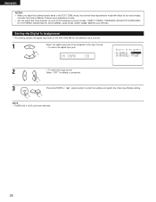
... Mode setting. Setting the Digital In Assignment • This setting assigns the digital input jacks of the AVR-1905/785 for each of the following surround modes: DIRECT, STEREO, STANDARD (DOLBY/DTS SURROUND), 5/7 CH STEREO, MONO MOVIE, ROCK ARENA, JAZZ CLUB, VIDEO GAME, MATRIX and VIRTUAL. ENGLISH NOTES...: • When you adjust the channel levels while in the TEST TONE mode, the channel level adjustments made will affect all surround modes. Consider this mode a Master Channel Level adjustment mode. • You can adjust the channel levels for the different input sources....
... Mode setting. Setting the Digital In Assignment • This setting assigns the digital input jacks of the AVR-1905/785 for each of the following surround modes: DIRECT, STEREO, STANDARD (DOLBY/DTS SURROUND), 5/7 CH STEREO, MONO MOVIE, ROCK ARENA, JAZZ CLUB, VIDEO GAME, MATRIX and VIRTUAL. ENGLISH NOTES...: • When you adjust the channel levels while in the TEST TONE mode, the channel level adjustments made will affect all surround modes. Consider this mode a Master Channel Level adjustment mode. • You can adjust the channel levels for the different input sources....

Owners Manual
Page 27
... signal to be output from the composite and component monitor output terminal. The composite video input signal is no input signal to switch the Auto Surround Mode setting. The S-Video input signal is converted and output from the monitor output terminals. 1 Select the input source to be set. 21 DVD AUTO...
... signal to be output from the composite and component monitor output terminal. The composite video input signal is no input signal to switch the Auto Surround Mode setting. The S-Video input signal is converted and output from the monitor output terminals. 1 Select the input source to be set. 21 DVD AUTO...


