
Literature/Product Sheet
Page 1
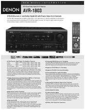
... with the DTS-ES (true discrete) 6.1 decoder, developed by DENON to accurately decode and reproduce the superior quality of DTS-ES Discrete 6.1, DTS-ES Matrix 6.1, DTS NEO:6, Dolby Digital EX and Dolby Pro Logic II. ■ Featuring DTS-ES Discrete 6.1 Decoding The AVR-1803 is rated at the rear for 6.1-channel surround sources...
... with the DTS-ES (true discrete) 6.1 decoder, developed by DENON to accurately decode and reproduce the superior quality of DTS-ES Discrete 6.1, DTS-ES Matrix 6.1, DTS NEO:6, Dolby Digital EX and Dolby Pro Logic II. ■ Featuring DTS-ES Discrete 6.1 Decoding The AVR-1803 is rated at the rear for 6.1-channel surround sources...
Literature/Product Sheet
Page 2
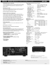
... response 10 Hz - 100 kHz (+1, -3 dB) (Tone Defeat On) Signal-to multiple zones. DENON, LTD. 3-16-11, YUSHIMA, BUNKYO-KU, TOKYO 113-0034, JAPAN 13010802 A The AVR-1803's Power Amplifier Assign function lets you assign the Surround Back (SB A/B) amplifier channels to instead drive the... Multi-room Zone powered speaker outputs, with terminal cover. (*1) Note on Movie mode: On DENON A/V receivers, this Movie mode is playing...
... response 10 Hz - 100 kHz (+1, -3 dB) (Tone Defeat On) Signal-to multiple zones. DENON, LTD. 3-16-11, YUSHIMA, BUNKYO-KU, TOKYO 113-0034, JAPAN 13010802 A The AVR-1803's Power Amplifier Assign function lets you assign the Surround Back (SB A/B) amplifier channels to instead drive the... Multi-room Zone powered speaker outputs, with terminal cover. (*1) Note on Movie mode: On DENON A/V receivers, this Movie mode is playing...
Owners Manual
Page 2
This Class B digital apparatus meets all requirements of uninsulated "dangerous voltage" within an equilateral triangle, is intended to alert the user to persons. NO USERSERVICEABLE PARTS INSIDE. REFER SERVICING TO QUALIFIED SERVICE PERSONNEL. Operation is subject to the following two conditions: (1) This device may not cause harmful interference, and (2) this device must accept any way. • Ne jamais démonter ou modifier l'appareil d'une manière ou d'une autre. Allow for sufficient heat dispersion when installed on a rack. • Eviter des températures &#...
This Class B digital apparatus meets all requirements of uninsulated "dangerous voltage" within an equilateral triangle, is intended to alert the user to persons. NO USERSERVICEABLE PARTS INSIDE. REFER SERVICING TO QUALIFIED SERVICE PERSONNEL. Operation is subject to the following two conditions: (1) This device may not cause harmful interference, and (2) this device must accept any way. • Ne jamais démonter ou modifier l'appareil d'une manière ou d'une autre. Allow for sufficient heat dispersion when installed on a rack. • Eviter des températures &#...
Owners Manual
Page 3
The safety and operating instructions should not be retained for this product through openings as recommended by a qualified technician to restore the product to its normal operation, e) If the product has been dropped or damaged in any kind into this product during a lightning storm, or when it is damaged, b) If liquid has been spilled, or objects have been adhered to rain or water, d) If the product does not operate normally by the manufacturer. 9. Follow Instructions - Unplug this product on an unstable cart, stand, tripod, bracket, or table. Water and Moisture - for example,...
The safety and operating instructions should not be retained for this product through openings as recommended by a qualified technician to restore the product to its normal operation, e) If the product has been dropped or damaged in any kind into this product during a lightning storm, or when it is damaged, b) If liquid has been spilled, or objects have been adhered to rain or water, d) If the product does not operate normally by the manufacturer. 9. Follow Instructions - Unplug this product on an unstable cart, stand, tripod, bracket, or table. Water and Moisture - for example,...
Owners Manual
Page 4
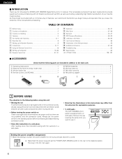
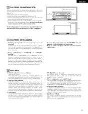
AUX jacks. AUX jacks The AVR-1803/883's front panel is provided with a V. Remove the cap covering the jacks when you for the surround back channel to use it. As this product ... power amplifier assignment: • Make this instructions along with the connection cords. After reading, store this setting to switch the power amplifier for choosing the DENON AVR-1803/883 Digital Surround A / V receiver. TABLE OF CONTENTS z Before Using 4 x Cautions on Installation 5 c Cautions on Check once again that all other audio components when moving the...
AUX jacks. AUX jacks The AVR-1803/883's front panel is provided with a V. Remove the cap covering the jacks when you for the surround back channel to use it. As this product ... power amplifier assignment: • Make this instructions along with the connection cords. After reading, store this setting to switch the power amplifier for choosing the DENON AVR-1803/883 Digital Surround A / V receiver. TABLE OF CONTENTS z Before Using 4 x Cautions on Installation 5 c Cautions on Check once again that all other audio components when moving the...
Owners Manual
Page 5
... SPEAKER terminals The PRE OUT jack, HEADPHONE jack and SPEAKER terminals include a muting circuit. DTS-ES Extended Surround and DTS Neo:6 The AVR-1803/883 is turned up is changed. If this happens, either turn down the MASTER VOLUME control or connect components to 5.1 channels of wide...with greater precision. 3. Dolby Pro Logic II decoder Dolby Pro Logic II is a new format for , say, a vacation. 4 FEATURES 1. The AVR-1803/883 is the default digital audio delivery system for superior picture quality. 7. Auto Surround Mode This function stores the surround mode last used to 5.1 ...
... SPEAKER terminals The PRE OUT jack, HEADPHONE jack and SPEAKER terminals include a muting circuit. DTS-ES Extended Surround and DTS Neo:6 The AVR-1803/883 is turned up is changed. If this happens, either turn down the MASTER VOLUME control or connect components to 5.1 channels of wide...with greater precision. 3. Dolby Pro Logic II decoder Dolby Pro Logic II is a new format for , say, a vacation. 4 FEATURES 1. The AVR-1803/883 is the default digital audio delivery system for superior picture quality. 7. Auto Surround Mode This function stores the surround mode last used to 5.1 ...

Owners Manual
Page 6
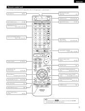
IN button 33, 35) o DOLBY/DTS SURROUND button 40, 42, 44, 45) !0 5CH/6CH STEREO button 48) !1 DIRECT/STEREO button 48) !2 TUNING UP/DOWN buttons 54) !3 V. ENGLISH 5 PART NAMES AND FUNCTIONS Front Panel • For details on the functions of these parts, refer to the pages given in parentheses ( ). #3 #2 #1 #0 @9 @8 @7 @6 @5 @4 @3 @2 @1 @0 !9 e t u o !1 !4 q w r y i !0 !2 !3 !5 !6 !7 !8 q Power ON/STANDBY switch 20, 32, 53) w Headphones jack (PHONES 36) e ZONE2/REC button 37) r ZONE2 button 37, 39, 56) t SURROUND BACK button 39, 45, 56) y TONE DEFEAT button 35) u ANALOG ...
IN button 33, 35) o DOLBY/DTS SURROUND button 40, 42, 44, 45) !0 5CH/6CH STEREO button 48) !1 DIRECT/STEREO button 48) !2 TUNING UP/DOWN buttons 54) !3 V. ENGLISH 5 PART NAMES AND FUNCTIONS Front Panel • For details on the functions of these parts, refer to the pages given in parentheses ( ). #3 #2 #1 #0 @9 @8 @7 @6 @5 @4 @3 @2 @1 @0 !9 e t u o !1 !4 q w r y i !0 !2 !3 !5 !6 !7 !8 q Power ON/STANDBY switch 20, 32, 53) w Headphones jack (PHONES 36) e ZONE2/REC button 37) r ZONE2 button 37, 39, 56) t SURROUND BACK button 39, 45, 56) y TONE DEFEAT button 35) u ANALOG ...
Owners Manual
Page 7
...~26, 29, 30, 41, 43) SURROUND BACK/RETURN button 29, 30, 45) DIMMER button 36) NOTE: • The shaded buttons do not function with the AVR-1803/883. (Nothing happens when they are pressed.) 7
...~26, 29, 30, 41, 43) SURROUND BACK/RETURN button 29, 30, 45) DIMMER button 36) NOTE: • The shaded buttons do not function with the AVR-1803/883. (Nothing happens when they are pressed.) 7
Owners Manual
Page 8
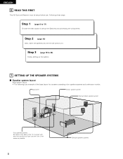
ENGLISH 6 READ THIS FIRST This AV Surround Receiver must be setup before use. Step 3 (page 19 to setup the Speakers and connecting the components. Following these at the sides of the TV or screen with their front surfaces as flush with the front of the screen as possible. 8 Surround speaker systems Step 2 (page 18) Next, insert the batteries into the remote control unit. Step 1 (page 8 to 17) Choose the best location to 26) Finally, setting up the system. 7 SETTING UP THE SPEAKER SYSTEMS 2 Speaker system layout Basic system layout • The following is an example of the basic ...
ENGLISH 6 READ THIS FIRST This AV Surround Receiver must be setup before use. Step 3 (page 19 to setup the Speakers and connecting the components. Following these at the sides of the TV or screen with their front surfaces as flush with the front of the screen as possible. 8 Surround speaker systems Step 2 (page 18) Next, insert the batteries into the remote control unit. Step 1 (page 8 to 17) Choose the best location to 26) Finally, setting up the system. 7 SETTING UP THE SPEAKER SYSTEMS 2 Speaker system layout Basic system layout • The following is an example of the basic ...
Owners Manual
Page 9
Connecting a turntable Connect the turntable's output cord to the AVR-1803/883's PHONO jacks, the L (left , right with digital output jacks R LRL INPUT OUTPUT tape deck, etc., move the tape deck away. Ground wire Turntable (MM ...
Connecting a turntable Connect the turntable's output cord to the AVR-1803/883's PHONO jacks, the L (left , right with digital output jacks R LRL INPUT OUTPUT tape deck, etc., move the tape deck away. Ground wire Turntable (MM ...

Owners Manual
Page 10
AUDIO VIDEO OUT R L OUT TV or DBS tuner B RL Connecting a TV/DBS tuner TV/DBS • Connect the TV's or DBS tuner's video output jack (VIDEO OUTPUT) to the VIDEO (yellow) TV/DBS IN jack using a 75 Ω/ohms video coaxial pin plug cord. • Connect the TV's or DBS tuner's audio output jacks (AUDIO OUTPUT) to the VIDEO MONITOR OUT jack using pin plug cords. Monitor TV AUDIO VIDEO B OUT R L OUT DVD player or video disc player (VDP), etc. Connecting a Monitor TV MONITOR OUT • Connect the TV's video input jack (VIDEO INPUT) to VIDEO IN the AUDIO TV/DBS IN jacks...
AUDIO VIDEO OUT R L OUT TV or DBS tuner B RL Connecting a TV/DBS tuner TV/DBS • Connect the TV's or DBS tuner's video output jack (VIDEO OUTPUT) to the VIDEO (yellow) TV/DBS IN jack using a 75 Ω/ohms video coaxial pin plug cord. • Connect the TV's or DBS tuner's audio output jacks (AUDIO OUTPUT) to the VIDEO MONITOR OUT jack using pin plug cords. Monitor TV AUDIO VIDEO B OUT R L OUT DVD player or video disc player (VDP), etc. Connecting a Monitor TV MONITOR OUT • Connect the TV's video input jack (VIDEO INPUT) to VIDEO IN the AUDIO TV/DBS IN jacks...

Owners Manual
Page 11
VIDEO OUTPUT) to the S-VIDEO TV/DBS IN jack using S jack connection cords. S-VIDEO IN OUT Video deck 2 Connecting the video decks • Connect the video deck's S output jack (S-OUT) to the S-VIDEO VCR-1 IN jack and the video deck's S input jack (S-IN) to the S-VIDEO VCR-1 OUT jack using S jack connection cords. • Connect the video deck's S output jack (S-OUT) to the S-VIDEO VCR-2 IN jack and the video deck's S input jack (S-IN) to the S-VIDEO VCR-2 OUT jack using an S jack connection cord. S-VIDEO OUT DVD player or video disc player (VDP) B S-VIDEO OUT Connecting a TV/...
VIDEO OUTPUT) to the S-VIDEO TV/DBS IN jack using S jack connection cords. S-VIDEO IN OUT Video deck 2 Connecting the video decks • Connect the video deck's S output jack (S-OUT) to the S-VIDEO VCR-1 IN jack and the video deck's S input jack (S-IN) to the S-VIDEO VCR-1 OUT jack using S jack connection cords. • Connect the video deck's S output jack (S-OUT) to the S-VIDEO VCR-2 IN jack and the video deck's S input jack (S-IN) to the S-VIDEO VCR-2 OUT jack using an S jack connection cord. S-VIDEO OUT DVD player or video disc player (VDP) B S-VIDEO OUT Connecting a TV/...

Owners Manual
Page 12
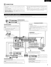
For details, carefully read the operating instructions included with Color Difference (Component - These terms all refer to component video color difference output. • At SYSTEM SETUP, the component video input terminal can be indicated differently on some TVs, monitors or video components ("CR, CB and Y", "R-Y, B-Y and Y", "Pr, Pb and Y", etc.). ENGLISH Connecting a Video Component Equipped with the TV or other components. • The signals input to the color difference (component) video jacks. • Some video sources with component video outputs such as a TV/DBS tuner, etc...
For details, carefully read the operating instructions included with Color Difference (Component - These terms all refer to component video color difference output. • At SYSTEM SETUP, the component video input terminal can be indicated differently on some TVs, monitors or video components ("CR, CB and Y", "R-Y, B-Y and Y", "Pr, Pb and Y", etc.). ENGLISH Connecting a Video Component Equipped with the TV or other components. • The signals input to the color difference (component) video jacks. • Some video sources with component video outputs such as a TV/DBS tuner, etc...

Owners Manual
Page 13
Connecting the antenna terminals DIRECTION OF BROADCASTING STATION FM ANTENNA 75 Ω/ohms COAXIAL CABLE FM ANTENNA ADAPTER (Supplied) FEEDER CABLE FM INDOOR ANTENNA (Supplied) AM loop antenna assembly 1 2 Connect to the point of cable entry as close to the AM antenna terminals. 3 Remove the vinyl tie and take out the connection line. 4 a. Return the lever. Notes: • Do not connect two FM antennas simultaneously. • Even if an external AM antenna is provided to call the CATV system installer's attention to Article 820-40 of the NEC which provides guidelines for...
Connecting the antenna terminals DIRECTION OF BROADCASTING STATION FM ANTENNA 75 Ω/ohms COAXIAL CABLE FM ANTENNA ADAPTER (Supplied) FEEDER CABLE FM INDOOR ANTENNA (Supplied) AM loop antenna assembly 1 2 Connect to the point of cable entry as close to the AM antenna terminals. 3 Remove the vinyl tie and take out the connection line. 4 a. Return the lever. Notes: • Do not connect two FM antennas simultaneously. • Even if an external AM antenna is provided to call the CATV system installer's attention to Article 820-40 of the NEC which provides guidelines for...

Owners Manual
Page 14
LINE OUT DIGITAL OUT VIDEO OUT S-VIDEO OUT LR 14 Video camera RL OUTPUT VIDEO OUT S-VIDEO OUT RL Connecting a video camera component • Connect the video camera component's output jacks to this unit's V. ENGLISH Connecting the external input (EXT. IN) jacks, see page 35. LINE OUT VIDEO OUT S-VIDEO OUT The V. Connecting the video component equipped with a cap. Video game OUTPUT R L OPTICAL VIDEO OUT S-VIDEO OUT RL Connecting a Video game component • Connect the Video game component's output jacks to this unit's V. AUX INPUT jacks. AUX jacks To ...
LINE OUT DIGITAL OUT VIDEO OUT S-VIDEO OUT LR 14 Video camera RL OUTPUT VIDEO OUT S-VIDEO OUT RL Connecting a video camera component • Connect the video camera component's output jacks to this unit's V. ENGLISH Connecting the external input (EXT. IN) jacks, see page 35. LINE OUT VIDEO OUT S-VIDEO OUT The V. Connecting the video component equipped with a cap. Video game OUTPUT R L OPTICAL VIDEO OUT S-VIDEO OUT RL Connecting a Video game component • Connect the Video game component's output jacks to this unit's V. AUX INPUT jacks. AUX jacks To ...

Owners Manual
Page 15
ZONE2 (A) (B) (Rear panel) NOTE: • To use ZONE2 with one speaker, to the SURR. BACK A and B terminals. BACK A CH. Then plug in the MAIN ZONE: • Set the POWER AMP ASSIGN switch to "SURR. Surround back speaker can be used to play a different program source in ZONE2 at the same time. ENGLISH Connecting the ZONE2 jacks • If another pre-main (integrated) amplifier is connected, the ZONE2 jacks can be used A + B. (Rear panel) To use the ZONE2 speaker system in ZONE2: • Set the POWER AMP ASSIGN switch to "ZONE 2". MAIN ZONE (A) (B) NOTE: &#...
ZONE2 (A) (B) (Rear panel) NOTE: • To use ZONE2 with one speaker, to the SURR. BACK A and B terminals. BACK A CH. Then plug in the MAIN ZONE: • Set the POWER AMP ASSIGN switch to "SURR. Surround back speaker can be used to play a different program source in ZONE2 at the same time. ENGLISH Connecting the ZONE2 jacks • If another pre-main (integrated) amplifier is connected, the ZONE2 jacks can be used A + B. (Rear panel) To use the ZONE2 speaker system in ZONE2: • Set the POWER AMP ASSIGN switch to "ZONE 2". MAIN ZONE (A) (B) NOTE: &#...

Owners Manual
Page 16
... ventilation around the unit, switch off and the power supply indicator LED flashes. Protector circuit • This unit is cut off the power and contact a DENON service center. Tighten by turning counterclockwise 2. Mismatching of polarities will result in contact with adjacent terminals, with other speaker cord conductors, or with an impedance...
... ventilation around the unit, switch off and the power supply indicator LED flashes. Protector circuit • This unit is cut off the power and contact a DENON service center. Tighten by turning counterclockwise 2. Mismatching of polarities will result in contact with adjacent terminals, with other speaker cord conductors, or with an impedance...

Owners Manual
Page 17
Connection jack for ZONE2. (See pge 4) (L) (R) SURROUND BACK/MULTI ZONE SPEAKER SYSTEMS SURROUND SPEAKER SYSTEMS • Precautions when connecting speakers If a speaker is placed near a TV or video monitor, the colors on the screen may be changed to use Surround back with built-in amplifier (super woofer), etc. If this should happen, move the speaker away to a position where it does not have this speaker for subwoofer with one speaker, connect the speaker to the operating instructions of the other components. FRONT SPEAKER SYSTEMS CENTER SPEAKER SYSTEM (L) (R) ...
Connection jack for ZONE2. (See pge 4) (L) (R) SURROUND BACK/MULTI ZONE SPEAKER SYSTEMS SURROUND SPEAKER SYSTEMS • Precautions when connecting speakers If a speaker is placed near a TV or video monitor, the colors on the screen may be changed to use Surround back with built-in amplifier (super woofer), etc. If this should happen, move the speaker away to a position where it does not have this speaker for subwoofer with one speaker, connect the speaker to the operating instructions of the other components. FRONT SPEAKER SYSTEMS CENTER SPEAKER SYSTEM (L) (R) ...
Owners Manual
Page 18
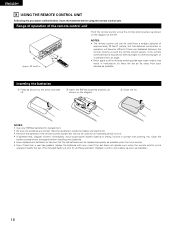
Range of operation of approximately 23 feet/7 meters, but this distance will shorten or operation will become difficult if there are correct. (See the illustration inside the battery compartment.) • Remove the batteries if the remote control transmitter will not be replaced as quickly as possible.) 18 Clean the battery compartment thoroughly before using the remote control unit. Replace it come in malfunction, so keep the set . (The included battery is exposed to direct sunlight or other strong light, or if operated from a straight distance of the remote control unit Point...
Range of operation of approximately 23 feet/7 meters, but this distance will shorten or operation will become difficult if there are correct. (See the illustration inside the battery compartment.) • Remove the batteries if the remote control transmitter will not be replaced as quickly as possible.) 18 Clean the battery compartment thoroughly before using the remote control unit. Replace it come in malfunction, so keep the set . (The included battery is exposed to direct sunlight or other strong light, or if operated from a straight distance of the remote control unit Point...

Owners Manual
Page 19
ENTER button Press this change what appears on the display. Front Sp. Default settings Surround Sp. Surround Back Sp. In SW Level Set the Ext. Large Center Sp. This assigns the digital input jacks for playing deep bass signals. AUX OFF OFF Auto surround mode function setting. Ext. CURSOR buttons (•, ª, 0, 1) Press this to switch the display. Small Small Normal Small Subwoofer Yes Crossover Frequency Delay Time Digital In Assignment Video In Assignment Auto Surround Mode Set the frequency (Hz) below on the display. OPTICAL 3 - - - Also use this ...
ENTER button Press this change what appears on the display. Front Sp. Default settings Surround Sp. Surround Back Sp. In SW Level Set the Ext. Large Center Sp. This assigns the digital input jacks for playing deep bass signals. AUX OFF OFF Auto surround mode function setting. Ext. CURSOR buttons (•, ª, 0, 1) Press this to switch the display. Small Small Normal Small Subwoofer Yes Crossover Frequency Delay Time Digital In Assignment Video In Assignment Auto Surround Mode Set the frequency (Hz) below on the display. OPTICAL 3 - - - Also use this ...
