
Owners Manual
Page 2
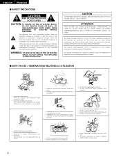
...ène et un diluant avec l'appareil. • Handle the power cord carefully. Tenir la prise lors du débranchement du cordon. * (For sets with Part 15 of the Canadian Interference-Causing Equipment Regulations. REFER SERVICING TO QUALIFIED SERVICE PERSONNEL. Cet appareil numérique de la classe B respecte toutes les...; Avoid high temperatures. WARNING: TO REDUCE THE RISK OF FIRE OR ELECTRIC SHOCK, DO NOT EXPOSE THIS APPLIANCE TO RAIN OR MOISTURE. NO USER-SERVICEABLE PARTS INSIDE.
...ène et un diluant avec l'appareil. • Handle the power cord carefully. Tenir la prise lors du débranchement du cordon. * (For sets with Part 15 of the Canadian Interference-Causing Equipment Regulations. REFER SERVICING TO QUALIFIED SERVICE PERSONNEL. Cet appareil numérique de la classe B respecte toutes les...; Avoid high temperatures. WARNING: TO REDUCE THE RISK OF FIRE OR ELECTRIC SHOCK, DO NOT EXPOSE THIS APPLIANCE TO RAIN OR MOISTURE. NO USER-SERVICEABLE PARTS INSIDE.
Owners Manual
Page 3
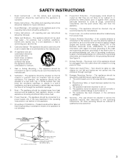
... IN WIRE ANTENNA DISCHARGE UNIT (NEC SECTION 810-20) GROUNDING CONDUCTORS (NEC SECTION 810-21) GROUND CLAMPS POWER SERVICE GROUNDING ELECTRODE SYSTEM (NEC ART 250, PART H) 3 The appliance should be mounted to service the appliance beyond that may impede the flow of the appliance should be unplugged from power lines. 16...
... IN WIRE ANTENNA DISCHARGE UNIT (NEC SECTION 810-20) GROUNDING CONDUCTORS (NEC SECTION 810-21) GROUND CLAMPS POWER SERVICE GROUNDING ELECTRODE SYSTEM (NEC ART 250, PART H) 3 The appliance should be mounted to service the appliance beyond that may impede the flow of the appliance should be unplugged from power lines. 16...
Owners Manual
Page 4
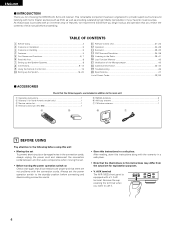
... the power cord and disconnect the connection cords between all connections are not problems with the connection cords. AUX terminal The AVR-1602's front panel is provided with an immense array of features, we recommend that before you begin hookup and operation that you...46 ¤0 Specifications 47 List of Preset Codes 92, 93 2 ACCESSORIES Check that the following parts are included in addition to the main unit: q Operating instructions 1 w Warranty ( for choosing the DENON A/V Surround receiver. Remove the cap covering the terminal when you for North America model only 1...
... the power cord and disconnect the connection cords between all connections are not problems with the connection cords. AUX terminal The AVR-1602's front panel is provided with an immense array of features, we recommend that before you begin hookup and operation that you...46 ¤0 Specifications 47 List of Preset Codes 92, 93 2 ACCESSORIES Check that the following parts are included in addition to the main unit: q Operating instructions 1 w Warranty ( for choosing the DENON A/V Surround receiver. Remove the cap covering the terminal when you for North America model only 1...

Owners Manual
Page 6
... AND FUNCTIONS Front Panel • For details on the functions of these parts, refer to the pages given in parentheses ( ). #0 @9 @8 @7 @6 @5 @4@3 @2 @1 @0 !9 !8 !7 !6 B yi !2 q w e r t u o !0 !1 !3 !4 !5 q Power operation switch 17, 24, 39) w Headphones jack (PHONES 27) e Preset station selector buttons 41) r SPEAKER A/B buttons ...
... AND FUNCTIONS Front Panel • For details on the functions of these parts, refer to the pages given in parentheses ( ). #0 @9 @8 @7 @6 @5 @4@3 @2 @1 @0 !9 !8 !7 !6 B yi !2 q w e r t u o !0 !1 !3 !4 !5 q Power operation switch 17, 24, 39) w Headphones jack (PHONES 27) e Preset station selector buttons 41) r SPEAKER A/B buttons ...
Owners Manual
Page 7
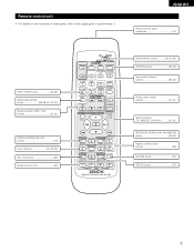
...) button 32, 35) Master volume control buttons 26) MUTING button 27) STATUS button 27) 7 Remote control unit • For details on the functions of these parts, refer to the pages given in parentheses ( ). ENGLISH Remote control signal transmitter 15) INPUT MODE button 25, 28) SURROUND MODE button 26, 29, 30, 32...) buttons 21, 23) SYSTEM (SYSTEM SET UP) buttons 16) Cursor buttons 16, 32, 35) Test tone button 29) System buttons (TV 23) CD MD/CDR AVR/AVC ON AUDIO POWER TV VCR VIDEO DVD/VDP OFF 1 CD DVD/VDP 2 3 V.
...) button 32, 35) Master volume control buttons 26) MUTING button 27) STATUS button 27) 7 Remote control unit • For details on the functions of these parts, refer to the pages given in parentheses ( ). ENGLISH Remote control signal transmitter 15) INPUT MODE button 25, 28) SURROUND MODE button 26, 29, 30, 32...) buttons 21, 23) SYSTEM (SYSTEM SET UP) buttons 16) Cursor buttons 16, 32, 35) Test tone button 29) System buttons (TV 23) CD MD/CDR AVR/AVC ON AUDIO POWER TV VCR VIDEO DVD/VDP OFF 1 CD DVD/VDP 2 3 V.

Owners Manual
Page 12
... system installer: This reminder is used, do not disconnect the AM loop antenna. • Make sure AM loop antenna lead terminals do not touch metal parts of AM antennas 1. ENGLISH Connecting the antenna terminals DIRECTION OF BROADCASTING STATION FM ANTENNA 75 Ω/ohms COAXIAL CABLE AM LOOP ANTENNA (An Accessory) AM...
... system installer: This reminder is used, do not disconnect the AM loop antenna. • Make sure AM loop antenna lead terminals do not touch metal parts of AM antennas 1. ENGLISH Connecting the antenna terminals DIRECTION OF BROADCASTING STATION FM ANTENNA 75 Ω/ohms COAXIAL CABLE AM LOOP ANTENNA (An Accessory) AM...