
Literature/Product Sheet
Page 1
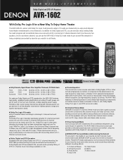
...from normal 5.1-channel DVD but from movie sources recorded in Dolby Digital, DTS or other formats emphasizes correction of speakers. The AVR-1602 features a Cinema Equalizer to correct these distinctly different sounding effects: 1. 5 Channel Stereo 2. s Virtual Surround Mode Surround ... Digital, Dolby Pro Logic II, and DTS surround modes) s 5 Channel Stereo Mode DENON's exclusive 5 Channel Stereo mode provides superb surround sound with Dolby Digital 5.1 encoded sources. The AVR-1602's Virtual Surround mode provides a dramatic psychoacoustic surround sound effect, using just one for a...
...from normal 5.1-channel DVD but from movie sources recorded in Dolby Digital, DTS or other formats emphasizes correction of speakers. The AVR-1602 features a Cinema Equalizer to correct these distinctly different sounding effects: 1. 5 Channel Stereo 2. s Virtual Surround Mode Surround ... Digital, Dolby Pro Logic II, and DTS surround modes) s 5 Channel Stereo Mode DENON's exclusive 5 Channel Stereo mode provides superb surround sound with Dolby Digital 5.1 encoded sources. The AVR-1602's Virtual Surround mode provides a dramatic psychoacoustic surround sound effect, using just one for a...
Literature/Product Sheet
Page 2
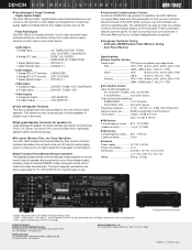
s High-grade Speaker Terminals (for speakers A): Large binding post speaker terminals has been provided for all of DENON's high-grade A/V amplifiers, the AVR-1602 lets you adjust delay times and other parameters so that you do not need to select the mode again for maximum ease-... recording device to operate other components in your home theater system, including codes for selected DENON models, along with remote control codes from digital sources such as CD. • Front Panel Inputs The AVR-1602's front panel includes 1 set of video and audio input terminals where you can customize ...
s High-grade Speaker Terminals (for speakers A): Large binding post speaker terminals has been provided for all of DENON's high-grade A/V amplifiers, the AVR-1602 lets you adjust delay times and other parameters so that you do not need to select the mode again for maximum ease-... recording device to operate other components in your home theater system, including codes for selected DENON models, along with remote control codes from digital sources such as CD. • Front Panel Inputs The AVR-1602's front panel includes 1 set of video and audio input terminals where you can customize ...
Owners Manual
Page 2
The lightning flash with arrowhead symbol, within an equilateral triangle, is intended to alert the user to the presence of uninsulated "dangerous voltage" within an equilateral triangle is subject to persons. CAUTION TO PREVENT ELECTRIC SHOCK, MATCH WIDE BLADE OF PLUG TO WIDE SLOT, FULLY INSERT. Operation is intended to alert the user to the presence of important operating and maintenance (servicing) instructions in the literature accompanying the appliance. NO USER-SERVICEABLE PARTS INSIDE. WARNING: TO REDUCE THE RISK OF FIRE OR ELECTRIC SHOCK, DO NOT EXPOSE THIS APPLIANCE TO RAIN OR...
The lightning flash with arrowhead symbol, within an equilateral triangle, is intended to alert the user to the presence of uninsulated "dangerous voltage" within an equilateral triangle is subject to persons. CAUTION TO PREVENT ELECTRIC SHOCK, MATCH WIDE BLADE OF PLUG TO WIDE SLOT, FULLY INSERT. Operation is intended to alert the user to the presence of important operating and maintenance (servicing) instructions in the literature accompanying the appliance. NO USER-SERVICEABLE PARTS INSIDE. WARNING: TO REDUCE THE RISK OF FIRE OR ELECTRIC SHOCK, DO NOT EXPOSE THIS APPLIANCE TO RAIN OR...
Owners Manual
Page 3
All the safety and operating instructions should be followed. 5. All operating and use instructions should be situated on or pinched by items placed upon or against voltage surges and built-up static charges. The appliance should not be taken so that the grounding or polarization means of the appliance should be read before the appliance is operated. 2. for the grounding electrode. Ventilation - For example, the appliance should be located away from the appliance. 14. Grounding or Polarization - Outdoor Antenna Grounding - Nonuse Periods - The power cord of an appliance...
All the safety and operating instructions should be followed. 5. All operating and use instructions should be situated on or pinched by items placed upon or against voltage surges and built-up static charges. The appliance should not be taken so that the grounding or polarization means of the appliance should be read before the appliance is operated. 2. for the grounding electrode. Ventilation - For example, the appliance should be located away from the appliance. 14. Grounding or Polarization - Outdoor Antenna Grounding - Nonuse Periods - The power cord of an appliance...
Owners Manual
Page 4
... may differ from the actual set for explanation purposes. • V. AUX terminal The AVR-1602's front panel is provided with an immense array of features, we recommend that before you begin hookup and operation that you for choosing the DENON A/V Surround receiver. Using the Remote Control Unit 15 ⁄0 Setting up the Speaker...
... may differ from the actual set for explanation purposes. • V. AUX terminal The AVR-1602's front panel is provided with an immense array of features, we recommend that before you begin hookup and operation that you for choosing the DENON A/V Surround receiver. Using the Remote Control Unit 15 ⁄0 Setting up the Speaker...

Owners Manual
Page 5
... and program sources even with audio formats of the future. 5 You can be set according to the input jacks. The remote control command codes for DENON remote controllable AV components as well as for use with stereo sources not in Dolby Surround but also regular stereo sources into five channels (front...
... and program sources even with audio formats of the future. 5 You can be set according to the input jacks. The remote control command codes for DENON remote controllable AV components as well as for use with stereo sources not in Dolby Surround but also regular stereo sources into five channels (front...

Owners Manual
Page 6
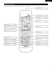
AUX INPUT jacks 4, 11) !2 SURROUND MODE button 26, 30, 32, 37) !3 SURROUND PARAMETER button 37) !4 SELECT UP/DOWN button 26, 29, 30, 32, 37) !5 TONE CONTROL button 26) !6 CH VOL button 29) !7 MASTER VOLUME control 26) !8 STATUS button 27) !9 DIMMER button 27) @0 Master volume indicator (VOLUME LEVEL 26) @1 Display @2 TUNING UP/DOWN button 40) @3 MEMORY button 39, 41) @4 MODE button 40) @5 BAND button 40) @6 SIGNAL indicators 26) @7 INPUT mode indicators 26) @8 Remote control sensor (REMOTE SENSOR 15) @9 Power operation indicator #0 Input source selector buttons 25, 32) 6 ...
AUX INPUT jacks 4, 11) !2 SURROUND MODE button 26, 30, 32, 37) !3 SURROUND PARAMETER button 37) !4 SELECT UP/DOWN button 26, 29, 30, 32, 37) !5 TONE CONTROL button 26) !6 CH VOL button 29) !7 MASTER VOLUME control 26) !8 STATUS button 27) !9 DIMMER button 27) @0 Master volume indicator (VOLUME LEVEL 26) @1 Display @2 TUNING UP/DOWN button 40) @3 MEMORY button 39, 41) @4 MODE button 40) @5 BAND button 40) @6 SIGNAL indicators 26) @7 INPUT mode indicators 26) @8 Remote control sensor (REMOTE SENSOR 15) @9 Power operation indicator #0 Input source selector buttons 25, 32) 6 ...
Owners Manual
Page 7
...) buttons 21, 23) SYSTEM (SYSTEM SET UP) buttons 16) Cursor buttons 16, 32, 35) Test tone button 29) System buttons (TV 23) CD MD/CDR AVR/AVC ON AUDIO POWER TV VCR VIDEO DVD/VDP OFF 1 CD DVD/VDP 2 3 V. Remote control unit • For details on the functions of these parts...
...) buttons 21, 23) SYSTEM (SYSTEM SET UP) buttons 16) Cursor buttons 16, 32, 35) Test tone button 29) System buttons (TV 23) CD MD/CDR AVR/AVC ON AUDIO POWER TV VCR VIDEO DVD/VDP OFF 1 CD DVD/VDP 2 3 V. Remote control unit • For details on the functions of these parts...
Owners Manual
Page 8
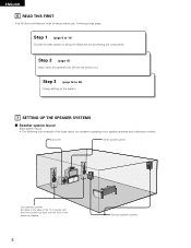
Step 1 (page 8 to 14) Choose the best location to 20) Finally, setting up the system. 7 SETTING UP THE SPEAKER SYSTEMS 2 Speaker system layout Basic system layout • The following is an example of the basic layout for a system consisting of the screen as possible. 8 Surround speaker systems Step 3 (page 16 to setup the Speakers and connecting the components. Following these at the sides of the TV or screen with their front surfaces as flush with the front of six speaker systems and a television monitor: Subwoofer Center speaker system Front speaker systems Set these steps....
Step 1 (page 8 to 14) Choose the best location to 20) Finally, setting up the system. 7 SETTING UP THE SPEAKER SYSTEMS 2 Speaker system layout Basic system layout • The following is an example of the basic layout for a system consisting of the screen as possible. 8 Surround speaker systems Step 3 (page 16 to setup the Speakers and connecting the components. Following these at the sides of the TV or screen with their front surfaces as flush with the front of six speaker systems and a television monitor: Subwoofer Center speaker system Front speaker systems Set these steps....

Owners Manual
Page 9
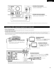
Connecting the audio components • Note that binding pin plug cords together with digital output. LINE OUT AC CORD AC 120V, 60Hz SURROUND SUB WOOFER CENTER FRONT RL AM LOOP ANT. FM COAX. R 75 L ANTENNA TERMINALS FR FL AUDIO R L IN CD DIGITAL IN DVD/ VDP TV/ DBS COAXIAL VCR CDR/ OPTICAL TAPE PRE OUT SUB WOOFER DVD/ VDP IN TV/ DBS VCR MONITOR SW C L R SR SL EXT. OPTICAL B OUTPUT INPUT OUTPUT RL CD player RL DIGITAL AUDIO DIGITAL jacks Use these for connections to Page 20 for hair driers, TVs or other electrical appliances. If this happens, turn ...
Connecting the audio components • Note that binding pin plug cords together with digital output. LINE OUT AC CORD AC 120V, 60Hz SURROUND SUB WOOFER CENTER FRONT RL AM LOOP ANT. FM COAX. R 75 L ANTENNA TERMINALS FR FL AUDIO R L IN CD DIGITAL IN DVD/ VDP TV/ DBS COAXIAL VCR CDR/ OPTICAL TAPE PRE OUT SUB WOOFER DVD/ VDP IN TV/ DBS VCR MONITOR SW C L R SR SL EXT. OPTICAL B OUTPUT INPUT OUTPUT RL CD player RL DIGITAL AUDIO DIGITAL jacks Use these for connections to Page 20 for hair driers, TVs or other electrical appliances. If this happens, turn ...

Owners Manual
Page 10
Monitor TV RL AM LOOP ANT. R FM COAX. Using an improper cable can also be connected to the AUDIO DVD/VDP IN jacks using pin plug cords. • For better sound quality, we recommend using 75 Ω/ohms video coaxial pin plug cords. DVD and VDP players can result in a drop in sound quality. IN AUDIO R L IN CD DIGITAL IN DVD/ VDP TV/ DBS COAXIAL VCR CDR/ OPTICAL TAPE VCR CDR/ TAPE OPTICAL OUT OUT PRE OUT SUB WOOFER DVD/ VDP IN TV/ DBS VCR MONITOR VCR OUT VIDEO VIDEO IN NOTE: Connection of the adapter when making connections. VIDEO IN VIDEO IN AUDIO VIDEO DIGITAL ...
Monitor TV RL AM LOOP ANT. R FM COAX. Using an improper cable can also be connected to the AUDIO DVD/VDP IN jacks using pin plug cords. • For better sound quality, we recommend using 75 Ω/ohms video coaxial pin plug cords. DVD and VDP players can result in a drop in sound quality. IN AUDIO R L IN CD DIGITAL IN DVD/ VDP TV/ DBS COAXIAL VCR CDR/ OPTICAL TAPE VCR CDR/ TAPE OPTICAL OUT OUT PRE OUT SUB WOOFER DVD/ VDP IN TV/ DBS VCR MONITOR VCR OUT VIDEO VIDEO IN NOTE: Connection of the adapter when making connections. VIDEO IN VIDEO IN AUDIO VIDEO DIGITAL ...
Owners Manual
Page 11
AUX INPUT lacks. AUX INPUT lacks. The V. S-VIDEO IN Monitor TV S-VIDEO OUT Connecting a monitor TV MONITOR OUT • Connect the TV's or DBS tuner's S video input (S-VIDEO INPUT) to this unit with S-jacks, keep the above point in mind and make connections according to the S-VIDEO DVD/VDP IN jack using an S-Video connection cord. Video camera AUDIO RL VIDEO VIDEO OUT RL Connecting a video camera equipment • Connect the video camera equipment's output jacks to the S-VIDEO MONITOR OUT jack using a S jack connection cord. When connecting this unit's V. DVD/ VDP FM ...
AUX INPUT lacks. AUX INPUT lacks. The V. S-VIDEO IN Monitor TV S-VIDEO OUT Connecting a monitor TV MONITOR OUT • Connect the TV's or DBS tuner's S video input (S-VIDEO INPUT) to this unit with S-jacks, keep the above point in mind and make connections according to the S-VIDEO DVD/VDP IN jack using an S-Video connection cord. Video camera AUDIO RL VIDEO VIDEO OUT RL Connecting a video camera equipment • Connect the video camera equipment's output jacks to the S-VIDEO MONITOR OUT jack using a S jack connection cord. When connecting this unit's V. DVD/ VDP FM ...

Owners Manual
Page 12
With the antenna on wall, etc. Connection of the building, as practical. Push the lever. 2. FM COAX. 75 ANTENNA TERMINALS FR FL AUDIO R L IN CD DIGITAL IN DVD/ VDP TV/ DBS COAXIAL VCR CDR/ OPTICAL TAPE SW C VCR SR SL EXT. Return the lever. Mount b. Installation hole Mount on top any stable surface. Notes: • Do not connect two FM antennas simultaneously. • Even if an external AM antenna is provided to call the CATV system installer's attention to Article 820-40 of the panel. 12 With the antenna attached to the AM antenna terminals. 3 ...
With the antenna on wall, etc. Connection of the building, as practical. Push the lever. 2. FM COAX. 75 ANTENNA TERMINALS FR FL AUDIO R L IN CD DIGITAL IN DVD/ VDP TV/ DBS COAXIAL VCR CDR/ OPTICAL TAPE SW C VCR SR SL EXT. Return the lever. Mount b. Installation hole Mount on top any stable surface. Notes: • Do not connect two FM antennas simultaneously. • Even if an external AM antenna is provided to call the CATV system installer's attention to Article 820-40 of the panel. 12 With the antenna attached to the AM antenna terminals. 3 ...

Owners Manual
Page 13
NOTE: NEVER touch the speaker terminals when the power is on the screen may be disturbed by the speaker's magnetism. Connecting the speaker cords 3. Return the lever. Connection jack for use a unit that can sufficiently reproduce frequencies of under 80 Hz. (L) (R) SURROUND SPEAKER SYSTEMS • Precautions when connecting speakers If a speaker is played for long periods of time at the same time, since use of speakers with an impedance of 12 to 16 Ω/ohms. • Speakers with an impedance of 6 to 16 Ω/ohms can be connected for use as center and surround ...
NOTE: NEVER touch the speaker terminals when the power is on the screen may be disturbed by the speaker's magnetism. Connecting the speaker cords 3. Return the lever. Connection jack for use a unit that can sufficiently reproduce frequencies of under 80 Hz. (L) (R) SURROUND SPEAKER SYSTEMS • Precautions when connecting speakers If a speaker is played for long periods of time at the same time, since use of speakers with an impedance of 12 to 16 Ω/ohms. • Speakers with an impedance of 6 to 16 Ω/ohms can be connected for use as center and surround ...
Owners Manual
Page 14
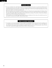
... the protection circuit is used at high volumes when speakers with the wiring or the ventilation around the unit, switch off the power and contact a DENON service center. The purpose of this unit, check whether there are any faults with a high-speed protection circuit. ENGLISH Protector circuit • This unit is...
... the protection circuit is used at high volumes when speakers with the wiring or the ventilation around the unit, switch off the power and contact a DENON service center. The purpose of this unit, check whether there are any faults with a high-speed protection circuit. ENGLISH Protector circuit • This unit is...
Owners Manual
Page 15
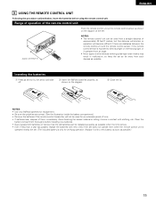
ENGLISH 9 USING THE REMOTE CONTROL UNIT Following the procedure outlined below, insert the batteries before installing new batteries. • Have replacement batteries on hand so that the old batteries can be used from a straight distance of approximately 23 feet/7 meters, but this distance will shorten or operation will become difficult if there are correct. (See the illustration inside the battery compartment.) • Remove the batteries if the remote control transmitter will not be replaced as quickly as possible.) 15 Inserting the batteries q Press as shown on the diagram at ...
ENGLISH 9 USING THE REMOTE CONTROL UNIT Following the procedure outlined below, insert the batteries before installing new batteries. • Have replacement batteries on hand so that the old batteries can be used from a straight distance of approximately 23 feet/7 meters, but this distance will shorten or operation will become difficult if there are correct. (See the illustration inside the battery compartment.) • Remove the batteries if the remote control transmitter will not be replaced as quickly as possible.) 15 Inserting the batteries q Press as shown on the diagram at ...

Owners Manual
Page 16
SELECT button Press this unit. 1 Set the slide switch to "AUDIO". Digital Inputs Input source COAXIAL DVD/VDP OPTICAL TV/DBS Center 0 dB Surround L Surround R 0 dB 0 dB Sub Woofer Yes - - - - Also use this button to complete the setting. • System setup items and default values (set upon shipment from the factory) Speaker Configuration System setup Input the combination of speakers in your system and their corresponding sizes (SMALL for regular speakers, LARGE for full-size, full-range) to automatically set up the system: VIDEO SELECT CD·MD/CDR·DVD/VDP ...
SELECT button Press this unit. 1 Set the slide switch to "AUDIO". Digital Inputs Input source COAXIAL DVD/VDP OPTICAL TV/DBS Center 0 dB Surround L Surround R 0 dB 0 dB Sub Woofer Yes - - - - Also use this button to complete the setting. • System setup items and default values (set upon shipment from the factory) Speaker Configuration System setup Input the combination of speakers in your system and their corresponding sizes (SMALL for regular speakers, LARGE for full-size, full-range) to automatically set up the system: VIDEO SELECT CD·MD/CDR·DVD/VDP ...

Owners Manual
Page 17
System set up. The changes to the settings made up to that all the components are entered. Setting the speaker configuration 1 Use the (left) and (right) buttons to select your front speaker type. (Initial) 1 FRONT LARGE LARGE SMALL Press the SELECT or (left) button (right) button (down) button to switch to the center speaker setting. 2 Use the (left) and (right) buttons to select your surround speaker type. (Initial) 3 SURR. ENGLISH Before setting up the system 1 Check that point are correct, then press the POWER operation switch on the main unit or the POWER button on ...
System set up. The changes to the settings made up to that all the components are entered. Setting the speaker configuration 1 Use the (left) and (right) buttons to select your front speaker type. (Initial) 1 FRONT LARGE LARGE SMALL Press the SELECT or (left) button (right) button (down) button to switch to the center speaker setting. 2 Use the (left) and (right) buttons to select your surround speaker type. (Initial) 3 SURR. ENGLISH Before setting up the system 1 Check that point are correct, then press the POWER operation switch on the main unit or the POWER button on ...

Owners Manual
Page 18
When this playback mode there tends to be little interference of below 80 Hz are assigned to the subwoofer. If "SMALL" is set for the front speakers or "NO" is selected, low frequencies of the low frequency range in the room. • Try playing the music or movie source and select the playback mode providing the stronger low frequency range sound. 18 In this setting is set for the subwoofer in a decrease of the actual volume of the low frequency range. • When the "NORM" playback mode is selected, the low frequency signal range of channels set "Subwoofer = No", or ...
When this playback mode there tends to be little interference of below 80 Hz are assigned to the subwoofer. If "SMALL" is set for the front speakers or "NO" is selected, low frequencies of the low frequency range in the room. • Try playing the music or movie source and select the playback mode providing the stronger low frequency range sound. 18 In this setting is set for the subwoofer in a decrease of the actual volume of the low frequency range. • When the "NORM" playback mode is selected, the low frequency signal range of channels set "Subwoofer = No", or ...

Owners Manual
Page 19
ENGLISH Setting the speaker distance Input the distances from the center speakers to the listening 7 CENTER 12ft • The number changes in units of 1 foot each time one of the buttons is pressed. L1: Distance from center speaker to listening position L2: Distance from front speakers to listening position L3: Distance from surround speaker to listening position CAUTION: Set the center speaker at the same distance from the front speakers and subwoofer to set the distance from the front speakers (left and right) or the subwoofer, or so that the difference in units of 1 foot each...
ENGLISH Setting the speaker distance Input the distances from the center speakers to the listening 7 CENTER 12ft • The number changes in units of 1 foot each time one of the buttons is pressed. L1: Distance from center speaker to listening position L2: Distance from front speakers to listening position L3: Distance from surround speaker to listening position CAUTION: Set the center speaker at the same distance from the front speakers and subwoofer to set the distance from the front speakers (left and right) or the subwoofer, or so that the difference in units of 1 foot each...
