Setup and Quick Reference Guide
Page 8
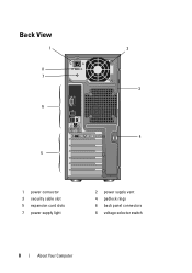
Back View 1 8 7 6 5 2 3 4 1 power connector 3 security cable slot 5 expansion card slots 7 power supply light 2 power supply vent 4 padlock rings 6 back panel connectors 8 voltage selector switch 8 About Your Computer
Back View 1 8 7 6 5 2 3 4 1 power connector 3 security cable slot 5 expansion card slots 7 power supply light 2 power supply vent 4 padlock rings 6 back panel connectors 8 voltage selector switch 8 About Your Computer
Setup and Quick Reference Guide
Page 29
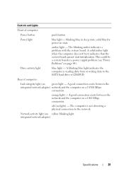
... or CD/DVD. A solid amber light when the computer does not boot indicates that the system board cannot start initialization. Rear of computer: Power button push button Power light blue light - orange light - The computer is reading data from or writing data to the network. Network activity light (on page 44...). Controls and Lights Front of computer: Link integrity light (on state amber light - blinking blue in sleep state; This could be a system board or a power supply problem (see "Power Problems" on yellow blinking light integrated network adapter) Specifications 29
... or CD/DVD. A solid amber light when the computer does not boot indicates that the system board cannot start initialization. Rear of computer: Power button push button Power light blue light - orange light - The computer is reading data from or writing data to the network. Network activity light (on page 44...). Controls and Lights Front of computer: Link integrity light (on state amber light - blinking blue in sleep state; This could be a system board or a power supply problem (see "Power Problems" on yellow blinking light integrated network adapter) Specifications 29
Setup and Quick Reference Guide
Page 30
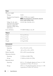
... 350 W Maximum heat dissipation 188 W (350-W power supply) (MHD) NOTE: Heat dissipation is calculated by using the power-supply wattage rating. Voltage (See the safety information that shipped with your computer for important voltage setting information.) 115/230 VAC, 50/60 Hz, 8/4 A Coin-cell ...
... 350 W Maximum heat dissipation 188 W (350-W power supply) (MHD) NOTE: Heat dissipation is calculated by using the power-supply wattage rating. Voltage (See the safety information that shipped with your computer for important voltage setting information.) 115/230 VAC, 50/60 Hz, 8/4 A Coin-cell ...
Service Manual
Page 1
... Microsoft Corporation in this document is a registered trademark of your computer. A00 Dell™ Vostro™ 410 Service Manual Troubleshooting Computer Cover PCI and PCI Express Cards I/O Panel Memory Processor System Board Contacting Dell Working on Your Computer Bezel Drives Fans Battery Power Supply System Setup Notes, Notices, and Cautions NOTE: A NOTE indicates important information that...
... Microsoft Corporation in this document is a registered trademark of your computer. A00 Dell™ Vostro™ 410 Service Manual Troubleshooting Computer Cover PCI and PCI Express Cards I/O Panel Memory Processor System Board Contacting Dell Working on Your Computer Bezel Drives Fans Battery Power Supply System Setup Notes, Notices, and Cautions NOTE: A NOTE indicates important information that...
Service Manual
Page 32
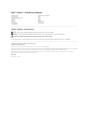
.... Note the routing of the computer chassis. 1 screws (4) 2 power supply 7. Slide the power supply towards the front of the power supply. 6. Removing the Power Supply 1. Remove the computer cover (see the Regulatory Compliance Homepage on Your Computer. 2. Back to Contents Page Power Supply Dell™ Vostro™ 410 Service Manual Removing the Power Supply Replacing the Power Supply Power Supply DC Connector Pin Assignments CAUTION: Before working inside your...
.... Note the routing of the computer chassis. 1 screws (4) 2 power supply 7. Slide the power supply towards the front of the power supply. 6. Removing the Power Supply 1. Remove the computer cover (see the Regulatory Compliance Homepage on Your Computer. 2. Back to Contents Page Power Supply Dell™ Vostro™ 410 Service Manual Removing the Power Supply Replacing the Power Supply Power Supply DC Connector Pin Assignments CAUTION: Before working inside your...
Service Manual
Page 33
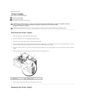
...CD or DVD drive data cable, and the front panel cables to prevent the cables from being damaged. 3. Verify that secure the power supply to make sure they are a key part of the computer chassis. CAUTION: Failure to replace and tighten all cable connections to the ...the procedure After Working on Your Computer. 6. Reconnect the DC power cables to replace and tighten all screws that the computer works correctly by running Dell Diagnostics. CAUTION: Failure to the system board and drives. 4. Power Supply DC Connector Pin Assignments 1. See your Setup and Quick Reference Guide...
...CD or DVD drive data cable, and the front panel cables to prevent the cables from being damaged. 3. Verify that secure the power supply to make sure they are a key part of the computer chassis. CAUTION: Failure to replace and tighten all cable connections to the ...the procedure After Working on Your Computer. 6. Reconnect the DC power cables to replace and tighten all screws that the computer works correctly by running Dell Diagnostics. CAUTION: Failure to the system board and drives. 4. Power Supply DC Connector Pin Assignments 1. See your Setup and Quick Reference Guide...
Service Manual
Page 57
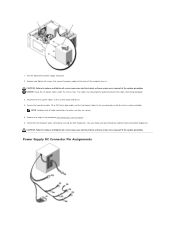
...If you are connected to the computer's front-panel headphone connector. See the setup diagram supplied with another device, such as shown on the setup diagram for troubleshooting purposes. If your ...and connect the monitor directly to the computer. For information about your screen. Check the monitor power light - Click or double-click the speaker icon in a safe and secure location. See...for bent or broken pins (it in the lower-right corner of the procedures in the Dell™ Technology Guide. See Hardware Troubleshooter. l Ensure that the headphone cable is normal for interference...
...If you are connected to the computer's front-panel headphone connector. See the setup diagram supplied with another device, such as shown on the setup diagram for troubleshooting purposes. If your ...and connect the monitor directly to the computer. For information about your screen. Check the monitor power light - Click or double-click the speaker icon in a safe and secure location. See...for bent or broken pins (it in the lower-right corner of the procedures in the Dell™ Technology Guide. See Hardware Troubleshooter. l Ensure that the headphone cable is normal for interference...
Service Manual
Page 61
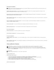
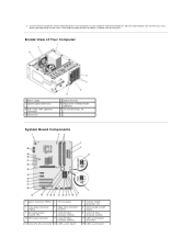
... and attached devices did not automatically turn off when you shut down your operating system, press and hold the power button for about 4 seconds to turn them off . Inside View of Your Computer 1 power supply 3 optional optical drive bays 5 USB, audio, 1394 (optional) connectors 7 chassis fan ` 2 optical drive bay 4 floppy drive or Media...
... and attached devices did not automatically turn off when you shut down your operating system, press and hold the power button for about 4 seconds to turn them off . Inside View of Your Computer 1 power supply 3 optional optical drive bays 5 USB, audio, 1394 (optional) connectors 7 chassis fan ` 2 optical drive bay 4 floppy drive or Media...


