Setup and Quick Reference Guide
Page 7
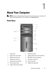
About Your Computer NOTE: For more information about the ports and connectors on your computer, see the Dell Technology Guide on your computer or at support.dell.com. Front View 1 2 3 13 4 5 6 7 12 8 11 9 10 1 optical drive 3 optical-drive eject button 5 USB 2.0 connectors (4) 7 headphone connector 9 power button, power light 11 front-panel door grip 13 optional optical-drive bays (2) 2 optical-drive panel 4 optional optical-drive eject buttons (2) 6 IEEE 1394 connector (optional) 8 microphone connector 10 drive activity light 12 FlexBay drive (optional) About Your Computer 7
About Your Computer NOTE: For more information about the ports and connectors on your computer, see the Dell Technology Guide on your computer or at support.dell.com. Front View 1 2 3 13 4 5 6 7 12 8 11 9 10 1 optical drive 3 optical-drive eject button 5 USB 2.0 connectors (4) 7 headphone connector 9 power button, power light 11 front-panel door grip 13 optional optical-drive bays (2) 2 optical-drive panel 4 optional optical-drive eject buttons (2) 6 IEEE 1394 connector (optional) 8 microphone connector 10 drive activity light 12 FlexBay drive (optional) About Your Computer 7
Setup and Quick Reference Guide
Page 15
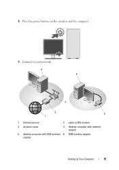
6 Press the power buttons on the monitor and the computer. 7 Connect to your network. 4 5 3 2 6 1 1 Internet service 2 cable or DSL modem 3 wireless router 4 desktop computer with network adapter 5 desktop computer with USB wireless 6 USB wireless adapter adapter Setting Up Your Computer 15
6 Press the power buttons on the monitor and the computer. 7 Connect to your network. 4 5 3 2 6 1 1 Internet service 2 cable or DSL modem 3 wireless router 4 desktop computer with network adapter 5 desktop computer with USB wireless 6 USB wireless adapter adapter Setting Up Your Computer 15
Setup and Quick Reference Guide
Page 29
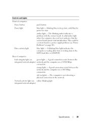
...or writing data to the network. blinking blue in sleep state; This could be a system board or a power supply problem (see "Power Problems" on a 1000 Mbps connection. Rear of computer: Power button push button Power light blue light - off (no light) - The blinking amber indicates a problem with the system board. ... the computer is not detecting a physical connection to the SATA hard drive or CD/DVD. solid blue for power-on state amber light - Drive activity light blue light - Controls and Lights Front of computer: Link integrity light (on green light -
...or writing data to the network. blinking blue in sleep state; This could be a system board or a power supply problem (see "Power Problems" on a 1000 Mbps connection. Rear of computer: Power button push button Power light blue light - off (no light) - The blinking amber indicates a problem with the system board. ... the computer is not detecting a physical connection to the SATA hard drive or CD/DVD. solid blue for power-on state amber light - Drive activity light blue light - Controls and Lights Front of computer: Link integrity light (on green light -
Setup and Quick Reference Guide
Page 33
...off or is not receiving power. • If the power light is steady blue and the computer is not responding, ensure that the display is connected and powered on the keyboard, move the mouse, or press the power button to resume normal operation. If the power light is blinking amber, the... computer is receiving electrical power, a device such as a memory module or graphics card might emit...
...off or is not receiving power. • If the power light is steady blue and the computer is not responding, ensure that the display is connected and powered on the keyboard, move the mouse, or press the power button to resume normal operation. If the power light is blinking amber, the... computer is receiving electrical power, a device such as a memory module or graphics card might emit...
Setup and Quick Reference Guide
Page 45
...outlet Memory Problems CAUTION: Before you are securely connected to the system board connector (see your Service Manual at support.dell.com). • Ensure that the main power cable and the front panel cable are not using to see if that resolves the problem. • See the ...Dell Diagnostics (see "Dell Diagnostics" on page 42). IF THE POWER LIGHT IS BLUE AND THE COMPUTER IS NOT RESPONDING - • Ensure that the display is connected and powered on. • If the display is connected and powered on, see "Beep Codes" on the keyboard, move the mouse, or press the power button ...
...outlet Memory Problems CAUTION: Before you are securely connected to the system board connector (see your Service Manual at support.dell.com). • Ensure that the main power cable and the front panel cable are not using to see if that resolves the problem. • See the ...Dell Diagnostics (see "Dell Diagnostics" on page 42). IF THE POWER LIGHT IS BLUE AND THE COMPUTER IS NOT RESPONDING - • Ensure that the display is connected and powered on. • If the display is connected and powered on, see "Beep Codes" on the keyboard, move the mouse, or press the power button ...
Setup and Quick Reference Guide
Page 46
...communicating with your computer. The computer does not start up ENSURE THAT THE POWER CABLE IS FIRMLY CONNECTED TO THE COMPUTER AND TO THE ELECTRICAL OUTLET The ... necessary, uninstall and then reinstall the program. 46 Troubleshooting IF YOU EXPERIENCE OTHER MEMORY PROBLEMS - • Reseat the memory modules (see "Dell Diagnostics" on page 42). Lockups and Software Problems CAUTION: Before you begin any of memory supported by pressing a key on a floppy disk..., press and hold the power button for at support.dell.com) to 10 seconds (until the computer turns off), and then ...
...communicating with your computer. The computer does not start up ENSURE THAT THE POWER CABLE IS FIRMLY CONNECTED TO THE COMPUTER AND TO THE ELECTRICAL OUTLET The ... necessary, uninstall and then reinstall the program. 46 Troubleshooting IF YOU EXPERIENCE OTHER MEMORY PROBLEMS - • Reseat the memory modules (see "Dell Diagnostics" on page 42). Lockups and Software Problems CAUTION: Before you begin any of memory supported by pressing a key on a floppy disk..., press and hold the power button for at support.dell.com) to 10 seconds (until the computer turns off), and then ...
Setup and Quick Reference Guide
Page 47
... for information. • Ensure that the program is compatible with the operating system installed on your keyboard or moving your mouse, press and hold the power button for at least 8 to 10 seconds (until the computer turns off), and then restart your computer meets the minimum hardware requirements needed to get a response...
... for information. • Ensure that the program is compatible with the operating system installed on your keyboard or moving your mouse, press and hold the power button for at least 8 to 10 seconds (until the computer turns off), and then restart your computer meets the minimum hardware requirements needed to get a response...
Service Manual
Page 1
Dell™ Vostro™ 410 Service Manual Troubleshooting Computer Cover PCI and PCI Express Cards I/O Panel Memory Processor System Board Contacting Dell Working on Your Computer Bezel Drives Fans Battery Power Supply System Setup Notes, Notices, and Cautions NOTE: A NOTE indicates important information that...Vista, and the Windows start button logo are either the entities claiming the marks and names or their products. disclaims any manner whatsoever without notice. © 2008 Dell Inc. Information in this text: Dell, the DELL logo, and Vostro are not applicable. Trademarks used...
Dell™ Vostro™ 410 Service Manual Troubleshooting Computer Cover PCI and PCI Express Cards I/O Panel Memory Processor System Board Contacting Dell Working on Your Computer Bezel Drives Fans Battery Power Supply System Setup Notes, Notices, and Cautions NOTE: A NOTE indicates important information that...Vista, and the Windows start button logo are either the entities claiming the marks and names or their products. disclaims any manner whatsoever without notice. © 2008 Dell Inc. Information in this text: Dell, the DELL logo, and Vostro are not applicable. Trademarks used...
Service Manual
Page 45
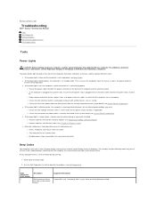
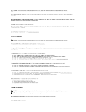
... mouse, or press the power button to further identify the problem. (see the Regulatory Compliance Homepage at www.dell.com/regulatory_compliance. l Eliminate interference. If your Setup and Quick Reference Guide). Back to Contents Page Troubleshooting Dell™ Vostro™ 410 Service Manual Tools Dell Diagnostics Solving Problems Dell Technical Update Service Dell Support Utility Tools Power Lights CAUTION: Before working...
... mouse, or press the power button to further identify the problem. (see the Regulatory Compliance Homepage at www.dell.com/regulatory_compliance. l Eliminate interference. If your Setup and Quick Reference Guide). Back to Contents Page Troubleshooting Dell™ Vostro™ 410 Service Manual Tools Dell Diagnostics Solving Problems Dell Technical Update Service Dell Support Utility Tools Power Lights CAUTION: Before working...

Service Manual
Page 53
... Programs® Use an older program with the operating system installed on your keyboard or moving your mouse, press and hold the power button for at least 8 to 10 seconds (until the computer turns off ), and then restart your computer meets the minimum hardware requirements... Task Manager. 2. l Verify that it runs in its documentation or on your keyboard or moving your mouse, press and hold the power button for an earlier Windows operating system Run the Program Compatibility Wizard - Follow the instructions on the screen. Windows Vista: The Program Compatibility Wizard...
... Programs® Use an older program with the operating system installed on your keyboard or moving your mouse, press and hold the power button for at least 8 to 10 seconds (until the computer turns off ), and then restart your computer meets the minimum hardware requirements... Task Manager. 2. l Verify that it runs in its documentation or on your keyboard or moving your mouse, press and hold the power button for an earlier Windows operating system Run the Program Compatibility Wizard - Follow the instructions on the screen. Windows Vista: The Program Compatibility Wizard...
Service Manual
Page 55
... manufacturer. Check the network cable connector - If the link integrity light (see System Board Components). Run the Hardware Troubleshooter - If the power light is blinking amber, beep code 3 - The computer is working by testing it with your computer. Press a key on the back...expansion cards, including graphics cards (see System Board Components). l Ensure that the electrical outlet is in the power connector on the keyboard, move the mouse, or press the power button to the network again Check your network settings - l Ensure that all memory modules (see System Board Components...
... manufacturer. Check the network cable connector - If the link integrity light (see System Board Components). Run the Hardware Troubleshooter - If the power light is blinking amber, beep code 3 - The computer is working by testing it with your computer. Press a key on the back...expansion cards, including graphics cards (see System Board Components). l Ensure that the electrical outlet is in the power connector on the keyboard, move the mouse, or press the power button to the network again Check your network settings - l Ensure that all memory modules (see System Board Components...
Service Manual
Page 58
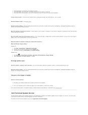
... connection - Test the electrical outlet - Ensure that the subwoofer is lit or blinking, the monitor has power. Turn off , firmly press the button to support.dell.com/technicalupdate. Click Start® Control Panel® Appearance and Themes. 2. If the external monitor works, ... for content, format, and how frequently you want to the computer. 2. See the monitor documentation for the Dell Technical Update service, go to ensure that the power cable for interference. Fans, fluorescent lights, halogen lamps, and other electrical devices can be defective. Windows Vista:...
... connection - Test the electrical outlet - Ensure that the subwoofer is lit or blinking, the monitor has power. Turn off , firmly press the button to support.dell.com/technicalupdate. Click Start® Control Panel® Appearance and Themes. 2. If the external monitor works, ... for content, format, and how frequently you want to the computer. 2. See the monitor documentation for the Dell Technical Update service, go to ensure that the power cable for interference. Fans, fluorescent lights, halogen lamps, and other electrical devices can be defective. Windows Vista:...
Service Manual
Page 60
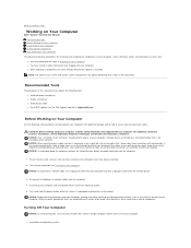
... your computer and all attached devices from the computer. 4. Turn off your computer, ground yourself by your computer. Press and hold the power button while the system is flat and clean to prevent the computer cover from the network device. 3. l You have already removed the original,... not covered by touching an unpainted metal surface, such as the metal at www.dell.com/regulatory_compliance. Back to Contents Page Working on Your Computer Dell™ Vostro™ 410 Service Manual Recommended Tools Before Working on Your Computer Inside View of Your Computer System Board ...
... your computer and all attached devices from the computer. 4. Turn off your computer, ground yourself by your computer. Press and hold the power button while the system is flat and clean to prevent the computer cover from the network device. 3. l You have already removed the original,... not covered by touching an unpainted metal surface, such as the metal at www.dell.com/regulatory_compliance. Back to Contents Page Working on Your Computer Dell™ Vostro™ 410 Service Manual Recommended Tools Before Working on Your Computer Inside View of Your Computer System Board ...
Service Manual
Page 61
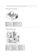
... USB, audio, 1394 (optional) connectors 7 chassis fan ` 2 optical drive bay 4 floppy drive or Media Reader (optional) 6 3.5-inch drive bays (4) System Board Components 1 power connector (PWR2) 2 CPU fan power 4 main power connector (PWR1) 5 floppy drive connector (FLOPPY) 7 password jumper (CLEAR_PW) 8 serial ATA drive connector (SATA2) 10 front panel connector 11 serial ATA drive connector... turned off . If your computer and attached devices did not automatically turn off when you shut down your operating system, press and hold the power button for about 4 seconds to turn them off .
... USB, audio, 1394 (optional) connectors 7 chassis fan ` 2 optical drive bay 4 floppy drive or Media Reader (optional) 6 3.5-inch drive bays (4) System Board Components 1 power connector (PWR2) 2 CPU fan power 4 main power connector (PWR1) 5 floppy drive connector (FLOPPY) 7 password jumper (CLEAR_PW) 8 serial ATA drive connector (SATA2) 10 front panel connector 11 serial ATA drive connector... turned off . If your computer and attached devices did not automatically turn off when you shut down your operating system, press and hold the power button for about 4 seconds to turn them off .


