User Manual
Page 2
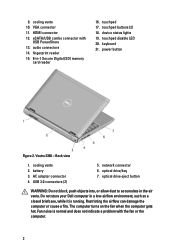
... combo connector with the fan or the computer. 2 AC adapter connector 4. Do not store your Dell computer in the air vents. HDMI connector 12. touchpad buttons (2) 18. keyboard 21. Vostro 3350 - USB 3.0 connectors (2) 5. optical drive/bay 7. optical drive eject button WARNING: Do ... fan when the computer gets hot. network connector 6. power button Figure 2. cooling vents 2. audio connectors 14. touchpad disable LED 20. battery 3. Fan noise is running. Back view 1. touchpad 17. fingerprint reader 15. 8-in-1 Secure Digital (SD) memory card reader 16....
... combo connector with the fan or the computer. 2 AC adapter connector 4. Do not store your Dell computer in the air vents. HDMI connector 12. touchpad buttons (2) 18. keyboard 21. Vostro 3350 - USB 3.0 connectors (2) 5. optical drive/bay 7. optical drive eject button WARNING: Do ... fan when the computer gets hot. network connector 6. power button Figure 2. cooling vents 2. audio connectors 14. touchpad disable LED 20. battery 3. Fan noise is running. Back view 1. touchpad 17. fingerprint reader 15. 8-in-1 Secure Digital (SD) memory card reader 16....
User Manual
Page 4
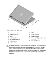
... cause a fire. Back view 1. cooling vents 8. USB 2.0 connector 11. 8-in the air vents. The computer turns on the fan when the computer gets hot. battery 4. USB 2.0 connector 3. AC adapter connector 6. ExpressCard reader WARNING: Do not block, push objects into, or allow dust to accumulate in -1 Secure Digital (SD)... memory card reader 12. Do not store your Dell computer in a low-airflow environment, such as a closed briefcase, while it is normal and does not indicate a problem with the fan or the computer...
... cause a fire. Back view 1. cooling vents 8. USB 2.0 connector 11. 8-in the air vents. The computer turns on the fan when the computer gets hot. battery 4. USB 2.0 connector 3. AC adapter connector 6. ExpressCard reader WARNING: Do not block, push objects into, or allow dust to accumulate in -1 Secure Digital (SD)... memory card reader 12. Do not store your Dell computer in a low-airflow environment, such as a closed briefcase, while it is normal and does not indicate a problem with the fan or the computer...
User Manual
Page 6
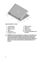
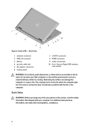
Vostro 3550 - VGA connector 6. USB 2.0 connector 8. Fan noise is running. Back View 1. cooling vents 9. security cable slot 2. HDMI connector 10. battery 5. e-SATA connector 11. 8-in-1 Secure Digital (SD) memory card reader WARNING: Do not block, push objects into, or allow dust to accumulate in a low-airflow ... computer gets hot. network connector 3. Restricting the airflow can damage the computer or cause a fire. Figure 6. USB 2.0 connector 4. AC adapter connector 7. Do not store your Dell computer in the air vents.
Vostro 3550 - VGA connector 6. USB 2.0 connector 8. Fan noise is running. Back View 1. cooling vents 9. security cable slot 2. HDMI connector 10. battery 5. e-SATA connector 11. 8-in-1 Secure Digital (SD) memory card reader WARNING: Do not block, push objects into, or allow dust to accumulate in a low-airflow ... computer gets hot. network connector 3. Restricting the airflow can damage the computer or cause a fire. Figure 6. USB 2.0 connector 4. AC adapter connector 7. Do not store your Dell computer in the air vents.
User Manual
Page 8
Vostro 3750 - e-SATA connector 8. Do not store your computer. The computer turns on the fan when the computer gets hot. Fan noise is running. HDMI connector 9. Figure 8. ... in the air vents. cooling vents 7. Restricting the airflow can damage the computer or cause a fire. battery 4. AC adapter connector 6. Back View 1. For additional best practices information, see www.dell.com/regulatory_compliance. 8 Quick Setup WARNING: Before you begin any of the procedures in this section, read the safety information that shipped with...
Vostro 3750 - e-SATA connector 8. Do not store your computer. The computer turns on the fan when the computer gets hot. Fan noise is running. HDMI connector 9. Figure 8. ... in the air vents. cooling vents 7. Restricting the airflow can damage the computer or cause a fire. battery 4. AC adapter connector 6. Back View 1. For additional best practices information, see www.dell.com/regulatory_compliance. 8 Quick Setup WARNING: Before you begin any of the procedures in this section, read the safety information that shipped with...
User Manual
Page 11
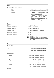
... Memory type Minimum memory Maximum memory Battery Vostro 3350 Type Dimensions: Depth Height Width Weight Intel Graphics Media Accelerator HD • AMD Radeon HD6470 GDDR5 - 512 MB (Vostro 3350 only) • AMD Radeon HD6630 - 1 GB VRAM (Vostro 3450 and Vostro 3550) • NVIDIA GeForce N12P GE(128 bit) - 1 GB (Vostro 3750 only) two SODIMM slots 1 GB, 2 GB...
... Memory type Minimum memory Maximum memory Battery Vostro 3350 Type Dimensions: Depth Height Width Weight Intel Graphics Media Accelerator HD • AMD Radeon HD6470 GDDR5 - 512 MB (Vostro 3350 only) • AMD Radeon HD6630 - 1 GB VRAM (Vostro 3450 and Vostro 3550) • NVIDIA GeForce N12P GE(128 bit) - 1 GB (Vostro 3750 only) two SODIMM slots 1 GB, 2 GB...
User Manual
Page 13
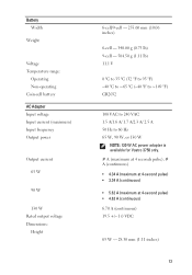
... Voltage Temperature range: Operating Non-operating Coin-cell battery AC Adapter Input voltage Input current (maximum) Input frequency Output power Output current 65 W 90 W 130 W Rated output voltage Dimensions: Height 6-cell/9-cell - ... ~149 °F) CR2032 100 VAC to 240 VAC 1.5 A/1.6 A/ 1.7 A/2.3 A/ 2.5 A 50 Hz to 60 Hz 65 W, 90 W, or 130 W NOTE: 130 W AC power adapter is available for Vostro 3750 only. # A (maximum at 4 seconds pulse), # A (continuous) • 4.34 A (maximum at 4-second pulse) • 3.34 A (continuous) • 5.62 A (maximum at 4-second pulse) • 4.62 A (continuous...
... Voltage Temperature range: Operating Non-operating Coin-cell battery AC Adapter Input voltage Input current (maximum) Input frequency Output power Output current 65 W 90 W 130 W Rated output voltage Dimensions: Height 6-cell/9-cell - ... ~149 °F) CR2032 100 VAC to 240 VAC 1.5 A/1.6 A/ 1.7 A/2.3 A/ 2.5 A 50 Hz to 60 Hz 65 W, 90 W, or 130 W NOTE: 130 W AC power adapter is available for Vostro 3750 only. # A (maximum at 4 seconds pulse), # A (continuous) • 4.34 A (maximum at 4-second pulse) • 3.34 A (continuous) • 5.62 A (maximum at 4-second pulse) • 4.62 A (continuous...

Owners Manual
Page 3
... on Your Computer 9 Before Working Inside Your Computer 9 Recommended Tools...11 Turning Off Your Computer 11 After Working Inside Your Computer 11 2 Battery...13 Removing The Battery...13 Installing The Battery...14 3 Secure Digital (SD) Card 15 Removing The Secure Digital (SD) Card 15 Installing The Secure Digital (SD) Card 16 4 ExpressCard 17...
... on Your Computer 9 Before Working Inside Your Computer 9 Recommended Tools...11 Turning Off Your Computer 11 After Working Inside Your Computer 11 2 Battery...13 Removing The Battery...13 Installing The Battery...14 3 Secure Digital (SD) Card 15 Removing The Secure Digital (SD) Card 15 Installing The Secure Digital (SD) Card 16 4 ExpressCard 17...
Owners Manual
Page 6
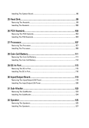
... 103 Installing The PCH Heatsink 104 27 Processor 107 Removing The Processor 107 Installing The Processor 108 28 Coin-Cell Battery 111 Removing The Coin-Cell Battery 111 Installing The Coin-Cell Battery 112 29 DC-In Port 115 Removing The DC-in Port 115 Installing The DC-in Port 116 30 Input...
... 103 Installing The PCH Heatsink 104 27 Processor 107 Removing The Processor 107 Installing The Processor 108 28 Coin-Cell Battery 111 Removing The Coin-Cell Battery 111 Installing The Coin-Cell Battery 112 29 DC-In Port 115 Removing The DC-in Port 115 Installing The DC-in Port 116 30 Input...

Owners Manual
Page 7
33 System Setup 129 System Setup Overview 129 System Setup Enter...129 System Setup Screens 130 System Setup Options 131 34 Diagnostics 135 Device Status Lights...135 Battery Status Lights...135 Diagnostic Beep Codes 135 35 Specifications 137 36 Contacting Dell 147 Contacting Dell...147
33 System Setup 129 System Setup Overview 129 System Setup Enter...129 System Setup Screens 130 System Setup Options 131 34 Diagnostics 135 Device Status Lights...135 Battery Status Lights...135 Diagnostic Beep Codes 135 35 Specifications 137 36 Contacting Dell 147 Contacting Dell...147
Owners Manual
Page 10
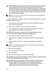
... or on its pull-tab, not on a flat work surface. Disconnect all attached devices from their electrical outlets. 6. Remove the main battery. 8. CAUTION: Before touching anything inside the computer. 1. While you disconnect the cable. To avoid damaging your computer and certain components may...Turn off your computer from the computer. 5. Some cables have connectors with locking tabs; Also, before you must remove the main battery before opening the display. Close the display and turn the computer upside-down on the cable itself. NOTE: To avoid damaging the...
... or on its pull-tab, not on a flat work surface. Disconnect all attached devices from their electrical outlets. 6. Remove the main battery. 8. CAUTION: Before touching anything inside the computer. 1. While you disconnect the cable. To avoid damaging your computer and certain components may...Turn off your computer from the computer. 5. Some cables have connectors with locking tabs; Also, before you must remove the main battery before opening the display. Close the display and turn the computer upside-down on the cable itself. NOTE: To avoid damaging the...

Owners Manual
Page 12
..., or media base, and replace any telephone or network cables to the computer, use batteries designed for this particular Dell computer. Connect your computer. 12 Turn on your computer and all attached devices to their electrical outlets. 5. Replace the battery. 4. Connect any cards, such as an ExpressCard. 2. CAUTION: To connect a network cable, first...
..., or media base, and replace any telephone or network cables to the computer, use batteries designed for this particular Dell computer. Connect your computer. 12 Turn on your computer and all attached devices to their electrical outlets. 5. Replace the battery. 4. Connect any cards, such as an ExpressCard. 2. CAUTION: To connect a network cable, first...
Owners Manual
Page 13
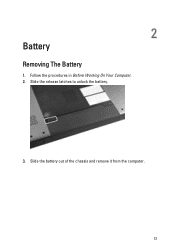
2 Battery Removing The Battery 1. Slide the battery out of the chassis and remove it from the computer. 13 Slide the release latches to unlock the battery. 3. Follow the procedures in Before Working On Your Computer. 2.
2 Battery Removing The Battery 1. Slide the battery out of the chassis and remove it from the computer. 13 Slide the release latches to unlock the battery. 3. Follow the procedures in Before Working On Your Computer. 2.

Owners Manual
Page 14
Slide the battery into its slot until it clicks into place. 2. Installing The Battery 1. Follow the procedures in After Working Inside Your Computer. 14
Slide the battery into its slot until it clicks into place. 2. Installing The Battery 1. Follow the procedures in After Working Inside Your Computer. 14

Owners Manual
Page 15
Press in Before Working On Your Computer. 2. Remove the SD card from the computer. 4. Remove the battery. 3. Follow the procedures in on the SD card to release it from the computer. 15 3 Secure Digital (SD) Card Removing The Secure Digital (SD) Card 1.
Press in Before Working On Your Computer. 2. Remove the SD card from the computer. 4. Remove the battery. 3. Follow the procedures in on the SD card to release it from the computer. 15 3 Secure Digital (SD) Card Removing The Secure Digital (SD) Card 1.

Owners Manual
Page 16
Installing The Secure Digital (SD) Card 1. Follow the procedures in After Working Inside Your Computer. 16 Install the battery. 3. Push the SD card into the slot until it clicks into place. 2.
Installing The Secure Digital (SD) Card 1. Follow the procedures in After Working Inside Your Computer. 16 Install the battery. 3. Push the SD card into the slot until it clicks into place. 2.

Owners Manual
Page 17
4 ExpressCard Removing The ExpressCard 1. Remove the battery. 3. Press the Express dummy card and the dummy card will pop out. 4. Take the Express dummy card out of the system. 17 Follow the procedures in Before Working On Your Computer. 2.
4 ExpressCard Removing The ExpressCard 1. Remove the battery. 3. Press the Express dummy card and the dummy card will pop out. 4. Take the Express dummy card out of the system. 17 Follow the procedures in Before Working On Your Computer. 2.

Owners Manual
Page 18
Slide the ExpressCard into its slot until it clicks into place. 2. Follow the procedures in After Working Inside Your Computer. 18 Installing The ExpressCard 1. Install the battery. 3.
Slide the ExpressCard into its slot until it clicks into place. 2. Follow the procedures in After Working Inside Your Computer. 18 Installing The ExpressCard 1. Install the battery. 3.

Owners Manual
Page 19
Remove the battery. 3. Press the keyboard down. Follow the procedures in Before Working On Your Computer. 2. Pry the keyboard with the use of a flat-head screwdriver towards the display to reveal the first keyboard retainer. 19 5 Keyboard Removing The Keyboard 1.
Remove the battery. 3. Press the keyboard down. Follow the procedures in Before Working On Your Computer. 2. Pry the keyboard with the use of a flat-head screwdriver towards the display to reveal the first keyboard retainer. 19 5 Keyboard Removing The Keyboard 1.

Owners Manual
Page 26
Connect the keyboard data cable to the back of the keyboard. 2. Install the battery. 6. If your computer comes with a backlit keyboard, connect the keyboard backlight cable. 3. Install the keyboard. 5. Installing The Keyboard 1. Replace the adhesive tape to secure the keyboard data cable to the back of the keyboard. 4. Follow the procedures in After Working Inside Your Computer. 26
Connect the keyboard data cable to the back of the keyboard. 2. Install the battery. 6. If your computer comes with a backlit keyboard, connect the keyboard backlight cable. 3. Install the keyboard. 5. Installing The Keyboard 1. Replace the adhesive tape to secure the keyboard data cable to the back of the keyboard. 4. Follow the procedures in After Working Inside Your Computer. 26

Owners Manual
Page 27
Follow the procedures in Before Working On Your Computer. 2. Pry up the memory door near the screw hole, lift, and remove it. 27 Remove the battery. 3. 6 Memory Door Removing The Memory Door 1. Loosen the screws that secure the memory door. 4.
Follow the procedures in Before Working On Your Computer. 2. Pry up the memory door near the screw hole, lift, and remove it. 27 Remove the battery. 3. 6 Memory Door Removing The Memory Door 1. Loosen the screws that secure the memory door. 4.

