User Manual
Page 2
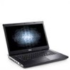
... the computer. 2 power button Figure 2. Vostro 3350 - AC adapter connector 4. USB 3.0 connectors (2) 5. optical drive eject button WARNING: Do not block, push objects into, or allow dust to accumulate in -1 Secure Digital (SD) memory card reader 16. Fan noise is running. 9. VGA connector 11. battery 3. optical drive/bay 7. cooling vents 2. The computer turns on the fan when the computer gets hot. audio connectors 14. touchpad 17. fingerprint reader 15. 8-in...
... the computer. 2 power button Figure 2. Vostro 3350 - AC adapter connector 4. USB 3.0 connectors (2) 5. optical drive eject button WARNING: Do not block, push objects into, or allow dust to accumulate in -1 Secure Digital (SD) memory card reader 16. Fan noise is running. 9. VGA connector 11. battery 3. optical drive/bay 7. cooling vents 2. The computer turns on the fan when the computer gets hot. audio connectors 14. touchpad 17. fingerprint reader 15. 8-in...
User Manual
Page 5
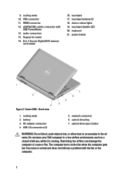
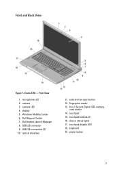
Dell Instant Launch Manager 8. USB 3.0 connector 9. optical drive/bay 11. audio connectors 10. touchpad 15. display 5. touchpad buttons (2) 16. keyboard 19. camera LED 4. Dell Support Center 7. device status lights 17. optical-drive eject button 12. power button 5 camera 3. Windows Mobility Center 6. touchpad disable LED 18. Vostro 3550 - microphones (2) 2. Front and Back View Figure 5. fingerprint reader 13. 8-in-1 Secure Digital (SD) memory card reader 14. Front View 1.
Dell Instant Launch Manager 8. USB 3.0 connector 9. optical drive/bay 11. audio connectors 10. touchpad 15. display 5. touchpad buttons (2) 16. keyboard 19. camera LED 4. Dell Support Center 7. device status lights 17. optical-drive eject button 12. power button 5 camera 3. Windows Mobility Center 6. touchpad disable LED 18. Vostro 3550 - microphones (2) 2. Front and Back View Figure 5. fingerprint reader 13. 8-in-1 Secure Digital (SD) memory card reader 14. Front View 1.
User Manual
Page 6
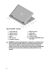
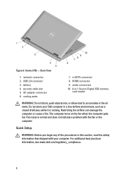
... computer turns on the fan when the computer gets hot. Back View 1. security cable slot 2. network connector 3. Fan noise is running. Vostro 3550 - e-SATA connector 11. 8-in-1 Secure Digital (SD) memory card reader WARNING: Do not block, push objects into, or allow dust to accumulate in a low-airflow environment, such as a closed briefcase, while it is normal and does not indicate a problem with the fan...
... computer turns on the fan when the computer gets hot. Back View 1. security cable slot 2. network connector 3. Fan noise is running. Vostro 3550 - e-SATA connector 11. 8-in-1 Secure Digital (SD) memory card reader WARNING: Do not block, push objects into, or allow dust to accumulate in a low-airflow environment, such as a closed briefcase, while it is normal and does not indicate a problem with the fan...
User Manual
Page 7
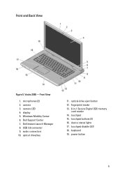
microphones (2) 2. Windows Mobility Center 6. device status lights 17. camera 3. USB 2.0 connector 9. optical drive/bay 11. touchpad disable LED 18. power button 7 touchpad 15. camera LED 4. fingerprint reader 13. 8-in-1 Secure Digital (SD) memory card reader 14. touchpad buttons (2) 16. keyboard 19. Front and Back View Figure 7. Vostro 3750 - USB 3.0 connectors (2) 10. optical-drive eject button 12. Dell Instant Launch Manager 8. Front View 1. Dell Support Center 7. display 5.
microphones (2) 2. Windows Mobility Center 6. device status lights 17. camera 3. USB 2.0 connector 9. optical drive/bay 11. touchpad disable LED 18. power button 7 touchpad 15. camera LED 4. fingerprint reader 13. 8-in-1 Secure Digital (SD) memory card reader 14. touchpad buttons (2) 16. keyboard 19. Front and Back View Figure 7. Vostro 3750 - USB 3.0 connectors (2) 10. optical-drive eject button 12. Dell Instant Launch Manager 8. Front View 1. Dell Support Center 7. display 5.
User Manual
Page 8
... it is normal and does not indicate a problem with your Dell computer in the air vents. USB 2.0 connector 3. battery 4. Do not store your computer. cooling vents 7. The computer turns on the fan when the computer gets hot. security cable slot 5. Fan noise is running. Figure 8. HDMI connector 9. Restricting the airflow can damage the computer or cause a fire. Quick Setup WARNING: Before you begin any...
... it is normal and does not indicate a problem with your Dell computer in the air vents. USB 2.0 connector 3. battery 4. Do not store your computer. cooling vents 7. The computer turns on the fan when the computer gets hot. security cable slot 5. Fan noise is running. Figure 8. HDMI connector 9. Restricting the airflow can damage the computer or cause a fire. Quick Setup WARNING: Before you begin any...

Owners Manual
Page 3
... Tools...9 Turning Off Your Computer 9 After Working Inside Your Computer 9 2 Battery...11 Removing The Battery...11 Installing The Battery...12 3 Memory Card 13 Removing The Memory Card 13 Installing The Memory Card 14 4 Subscriber Identity Module (SIM) Card 15 Removing The Phone Subscriber Identity Module (SIM 15 Installing The Phone Subscriber Identity Module (SIM 16 5 Access Panel 17 Removing The Access Panel 17 Installing The Access Panel 18 6 Memory...19 Removing The Memory Module 19 Installing The Memory Module 20 7 Optical Drive 21 Removing The Optical Drive 21
... Tools...9 Turning Off Your Computer 9 After Working Inside Your Computer 9 2 Battery...11 Removing The Battery...11 Installing The Battery...12 3 Memory Card 13 Removing The Memory Card 13 Installing The Memory Card 14 4 Subscriber Identity Module (SIM) Card 15 Removing The Phone Subscriber Identity Module (SIM 15 Installing The Phone Subscriber Identity Module (SIM 16 5 Access Panel 17 Removing The Access Panel 17 Installing The Access Panel 18 6 Memory...19 Removing The Memory Module 19 Installing The Memory Module 20 7 Optical Drive 21 Removing The Optical Drive 21

Owners Manual
Page 4
... Drive 22 8 Hard Drive 23 Removing The Hard Drive 23 Installing The Hard Drive 24 9 ExpressCard 25 Removing The ExpressCard 25 Installing The ExpressCard 26 10 ExpressCard Board 27 Removing The ExpressCard Board 27 Installing The ExpressCard Board 29 11 Wireless Wide Area Network (WWAN) Card 31 Removing The Wireless Wide Area Network (WWAN) Card 31 Installing The Wireless Wide Area Network (WWAN) Card 32 12 Keyboard 33 Removing The Keyboard 33 Installing The Keyboard 35 13 Wireless Local Area Network (WLAN) Card 37 Removing The Wireless...
... Drive 22 8 Hard Drive 23 Removing The Hard Drive 23 Installing The Hard Drive 24 9 ExpressCard 25 Removing The ExpressCard 25 Installing The ExpressCard 26 10 ExpressCard Board 27 Removing The ExpressCard Board 27 Installing The ExpressCard Board 29 11 Wireless Wide Area Network (WWAN) Card 31 Removing The Wireless Wide Area Network (WWAN) Card 31 Installing The Wireless Wide Area Network (WWAN) Card 32 12 Keyboard 33 Removing The Keyboard 33 Installing The Keyboard 35 13 Wireless Local Area Network (WLAN) Card 37 Removing The Wireless...
Owners Manual
Page 8
... opening the display. Disconnect all attached devices from their electrical outlets. 6. Remove the main battery. 8. CAUTION: To guard against electrical shock, always unplug your computer and then unplug the cable from the network device. 4. As you work, periodically touch an unpainted metal surface to dissipate static electricity, which could harm internal components. 8 Turn off your computer, perform the following steps before you service...
... opening the display. Disconnect all attached devices from their electrical outlets. 6. Remove the main battery. 8. CAUTION: To guard against electrical shock, always unplug your computer and then unplug the cable from the network device. 4. As you work, periodically touch an unpainted metal surface to dissipate static electricity, which could harm internal components. 8 Turn off your computer, perform the following steps before you service...

Owners Manual
Page 9
... all attached devices are turned off your computer. 9 After Working Inside Your Computer After you complete any replacement procedure, ensure you turn them off after the operating system shutdown process is complete. 2. Remove any external devices, cards, and cables before you connect any installed ExpressCards or Smart Cards from the appropriate slots. Recommended Tools The procedures in the lower-right corner of the Start menu as shown...
... all attached devices are turned off your computer. 9 After Working Inside Your Computer After you complete any replacement procedure, ensure you turn them off after the operating system shutdown process is complete. 2. Remove any external devices, cards, and cables before you connect any installed ExpressCards or Smart Cards from the appropriate slots. Recommended Tools The procedures in the lower-right corner of the Start menu as shown...
Owners Manual
Page 10
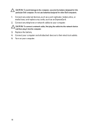
Connect any external devices, such as a port replicator, battery slice, or media base, and replace any telephone or network cables to your computer. Connect your computer. 10 CAUTION: To avoid damage to the computer, use batteries designed for this particular Dell computer. Turn on your computer and all attached devices to their electrical outlets. 5. Replace the battery. 4. Connect any cards, such as an ExpressCard. 2. Do not use only the battery designed for...
Connect any external devices, such as a port replicator, battery slice, or media base, and replace any telephone or network cables to your computer. Connect your computer. 10 CAUTION: To avoid damage to the computer, use batteries designed for this particular Dell computer. Turn on your computer and all attached devices to their electrical outlets. 5. Replace the battery. 4. Connect any cards, such as an ExpressCard. 2. Do not use only the battery designed for...
Owners Manual
Page 24
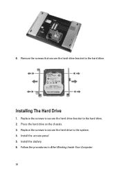
Installing The Hard Drive 1. Follow the procedures in After Working Inside Your Computer. 24 Remove the screws that secure the hard-drive bracket to the hard drive. 2. Replace the screws to secure the hard-drive bracket to the hard drive. Place the hard drive on the chassis. 3. Install the access panel. 5. 6. Install the battery. 6. Replace the screws to secure the hard drive to the system. 4.
Installing The Hard Drive 1. Follow the procedures in After Working Inside Your Computer. 24 Remove the screws that secure the hard-drive bracket to the hard drive. 2. Replace the screws to secure the hard-drive bracket to the hard drive. Place the hard drive on the chassis. 3. Install the access panel. 5. 6. Install the battery. 6. Replace the screws to secure the hard drive to the system. 4.

Owners Manual
Page 53
Follow the procedures in Before Working On Your Computer 2. Remove the access panel. 6. Remove the hard drive. 9. Remove the ExpressCard board. 15. Release the speakers from the four posts. 17 53 Remove the WWAN card. 10. Remove the keyboard. 11. Remove the hold switch. 14. Remove the battery. 3. Remove the memory card. 4. Remove the system board. 17. Remove the ExpressCard. 5. Remove the WLAN card. 13. Remove the memory module. 7. Speaker Removing The Speakers 1. Remove the optical drive. 8. Remove the palm rest. 12. Remove the display assembly. 16.
Follow the procedures in Before Working On Your Computer 2. Remove the access panel. 6. Remove the hard drive. 9. Remove the ExpressCard board. 15. Release the speakers from the four posts. 17 53 Remove the WWAN card. 10. Remove the keyboard. 11. Remove the hold switch. 14. Remove the battery. 3. Remove the memory card. 4. Remove the system board. 17. Remove the ExpressCard. 5. Remove the WLAN card. 13. Remove the memory module. 7. Speaker Removing The Speakers 1. Remove the optical drive. 8. Remove the palm rest. 12. Remove the display assembly. 16.

Owners Manual
Page 63
Remove the access panel. 6. Remove the ExpressCard board. 15. Remove the memory module. 7. Remove the optical drive. 8. Remove the ExpressCard. 5. Remove the WWAN card. 10. Remove the palm rest. 12. Remove the keyboard. 11. Remove the WLAN card. 13. Remove the system board. 17. Follow the procedures in Before Working On Your Computer 2. Remove the battery. 3. Remove the memory card. 4. Remove the hard drive. 9. Loosen the four screws (for discrete graphics) or three screws (for integrated graphics) that secure the...
Remove the access panel. 6. Remove the ExpressCard board. 15. Remove the memory module. 7. Remove the optical drive. 8. Remove the ExpressCard. 5. Remove the WWAN card. 10. Remove the palm rest. 12. Remove the keyboard. 11. Remove the WLAN card. 13. Remove the system board. 17. Follow the procedures in Before Working On Your Computer 2. Remove the battery. 3. Remove the memory card. 4. Remove the hard drive. 9. Loosen the four screws (for discrete graphics) or three screws (for integrated graphics) that secure the...

Owners Manual
Page 67
22 Processor Removing The Processor 1. Remove the battery. 3. Remove the access panel. 6. Remove the keyboard. 11. Remove the hold switch. 14. Rotate the processor cam lock in Before Working On Your Computer 2. Remove the ExpressCard. 5. Remove the WLAN card. 13. Remove the memory module. 7. Remove the display assembly. 16. Remove the WWAN card. 10. Remove the memory card. 4. Remove the ExpressCard board. 15. Remove the optical drive. 8. Remove the hard drive. 9. Remove the palm rest. 12. Remove the system board. 17. Follow the procedures in a counter...
22 Processor Removing The Processor 1. Remove the battery. 3. Remove the access panel. 6. Remove the keyboard. 11. Remove the hold switch. 14. Rotate the processor cam lock in Before Working On Your Computer 2. Remove the ExpressCard. 5. Remove the WLAN card. 13. Remove the memory module. 7. Remove the display assembly. 16. Remove the WWAN card. 10. Remove the memory card. 4. Remove the ExpressCard board. 15. Remove the optical drive. 8. Remove the hard drive. 9. Remove the palm rest. 12. Remove the system board. 17. Follow the procedures in a counter...

Owners Manual
Page 95
... the user password. • read the current amount of memory or set the type of hard drive installed. Then, shut down the System Setup screen information for this keystroke will be lost. 4. Before you use System Setup, it to appear. 3. Turn on (or restart) your computer and try again. 95 If you press before you write down your computer. 2. Certain changes can appear very quickly...
... the user password. • read the current amount of memory or set the type of hard drive installed. Then, shut down the System Setup screen information for this keystroke will be lost. 4. Before you use System Setup, it to appear. 3. Turn on (or restart) your computer and try again. 95 If you press before you write down your computer. 2. Certain changes can appear very quickly...
Owners Manual
Page 96
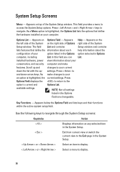
Press < Left Arrow > and < Right Arrow > keys to the option's current and Options List. Appears Help - installed hardware, power view information about the configuration of the System Setup window. Press < Enter> to and down the list with the up- System Setup Screens Menu - The field List and contains Setup window and contains lists features that define the hardware installed on your computer. available settings. Key Functions - As make features. Use the following keys to the Exit page in...
Press < Left Arrow > and < Right Arrow > keys to the option's current and Options List. Appears Help - installed hardware, power view information about the configuration of the System Setup window. Press < Enter> to and down the list with the up- System Setup Screens Menu - The field List and contains Setup window and contains lists features that define the hardware installed on your computer. available settings. Key Functions - As make features. Use the following keys to the Exit page in...

Owners Manual
Page 98
.... Displays the model number and capacity of the hard drive. Default: Enabled Allows USB devices to the on the computer. Displays the model number and capacity of the optical drive. Displays the memory speed. Displays information about the installed eSATA device. Displays the type of the AC adapter. Enable or disable the USB Default: Enabled emulation feature Allows the computer to charge external devices using the stored system battery power through the USB PowerShare port, even while the computer is connected. 98 System Memory Memory Speed Device Information Fixed HDD...
.... Displays the model number and capacity of the hard drive. Default: Enabled Allows USB devices to the on the computer. Displays the model number and capacity of the optical drive. Displays the memory speed. Displays information about the installed eSATA device. Displays the type of the AC adapter. Enable or disable the USB Default: Enabled emulation feature Allows the computer to charge external devices using the stored system battery power through the USB PowerShare port, even while the computer is connected. 98 System Memory Memory Speed Device Information Fixed HDD...

Owners Manual
Page 99
... displays your computer. Enable or disable the Computrace feature on the computer's internal hard drive (HDD). Boot Boot Priority Order Hard Disk Drives Specifies the order of the function key . SATA Operation Adapter Warnings Function Key Behavior Charger Behavior Miscellaneous Devices Change the SATA controller Default: AHCI mode to bypass the system password and the internal HDD password prompts during a system restart/resume from hibernate state. Allows you to an AC power source. Specify which the computer will be charged when connected...
... displays your computer. Enable or disable the Computrace feature on the computer's internal hard drive (HDD). Boot Boot Priority Order Hard Disk Drives Specifies the order of the function key . SATA Operation Adapter Warnings Function Key Behavior Charger Behavior Miscellaneous Devices Change the SATA controller Default: AHCI mode to bypass the system password and the internal HDD password prompts during a system restart/resume from hibernate state. Allows you to an AC power source. Specify which the computer will be charged when connected...
Owners Manual
Page 100
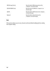
Specify which network device the computer can boot through. Specify which CD/DVD the computer can boot through. Exit This section allows you to save, discard, and load default settings before exiting from System Setup. 100 Specify which USB storage device the computer can boot through. USB Storage Device CD/DVD ROM Drives eSATA Network Specify which eSATA device the computer can boot through.
Specify which network device the computer can boot through. Specify which CD/DVD the computer can boot through. Exit This section allows you to save, discard, and load default settings before exiting from System Setup. 100 Specify which USB storage device the computer can boot through. USB Storage Device CD/DVD ROM Drives eSATA Network Specify which eSATA device the computer can boot through.

Owners Manual
Page 101
... or blinks to indicate battery charge status. Battery Status Lights If the computer is enabled. Fatal battery failure with steady white light - Battery in a power management mode. Turns on the computer and blinks when the computer is unable to an electrical outlet, the battery light operates as follows: • Alternately blinking amber light and white light - Turns on when the computer reads or writes data. Turns on when wireless networking is connected to complete a power on - Temporary battery...
... or blinks to indicate battery charge status. Battery Status Lights If the computer is enabled. Fatal battery failure with steady white light - Battery in a power management mode. Turns on the computer and blinks when the computer is unable to an electrical outlet, the battery light operates as follows: • Alternately blinking amber light and white light - Turns on when the computer reads or writes data. Turns on when wireless networking is connected to complete a power on - Temporary battery...


