Setup Guide
Page 5
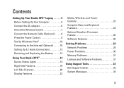
...Studio XPS™ Laptop 5 Before Setting Up Your Computer 5 Connect the AC adapter 6 Check the Wireless Control 7 Connect the Network Cable (Optional 8 Press the Power Control 9 Set Up Windows Vista 10 Connecting to the Internet (Optional 10 Setting Up 5.1 Audio Connections 12 Removing and Replacing the Battery 13 Using Your Studio XPS... 14 Device Status Lights 14 Right Side Features 16 Left Side Features 20 Display Features 22 Media, Wireless, and Power Controls 23...
...Studio XPS™ Laptop 5 Before Setting Up Your Computer 5 Connect the AC adapter 6 Check the Wireless Control 7 Connect the Network Cable (Optional 8 Press the Power Control 9 Set Up Windows Vista 10 Connecting to the Internet (Optional 10 Setting Up 5.1 Audio Connections 12 Removing and Replacing the Battery 13 Using Your Studio XPS... 14 Device Status Lights 14 Right Side Features 16 Left Side Features 20 Display Features 22 Media, Wireless, and Power Controls 23...
Setup Guide
Page 53
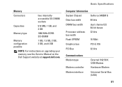
... System Chipset Data bus width GeForce 9400M G 64 bits DRAM bus width Processor address bus width Flash EPROM dual channel (2) 64-bit buses 32 bits 16 Mbit Graphics bus PCI-E X16 PCI Bus 32 bits Communications Modem type Modem controller Modem interface External V.92 56 K USB Modem Hardware Modem Universal Serial... DDR3 SO-DIMM Memory configuration possible 1 GB, 1.5 GB, 2 GB, 3 GB, and 4 GB NOTE: For instructions on upgrading your memory, see the Service Manual on the Dell Support website at support...
... System Chipset Data bus width GeForce 9400M G 64 bits DRAM bus width Processor address bus width Flash EPROM dual channel (2) 64-bit buses 32 bits 16 Mbit Graphics bus PCI-E X16 PCI Bus 32 bits Communications Modem type Modem controller Modem interface External V.92 56 K USB Modem Hardware Modem Universal Serial... DDR3 SO-DIMM Memory configuration possible 1 GB, 1.5 GB, 2 GB, 3 GB, and 4 GB NOTE: For instructions on upgrading your memory, see the Service Manual on the Dell Support website at support...
Setup Guide
Page 58
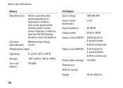
Basic Specifications Battery Operating time battery operating time varies depending on operating conditions and can be significantly reduced under certain power-intensive conditions (see the Dell Technology Guide for more information) Life span 300 discharge/charge (approximate) cycles Temperature range: Operating 0° to 35°C (32° to 95°F) Storage -... 100-240 VAC 1.5 A 50-60 Hz 65 W or 90 W 5.62 A (peak for 4-second pulse) 4.62 A (continuous) 4.34 A (peak for 4-second pulse) 3.34 A (continuous) 19.5 VDC 16 mm (0.62 in) 56
Basic Specifications Battery Operating time battery operating time varies depending on operating conditions and can be significantly reduced under certain power-intensive conditions (see the Dell Technology Guide for more information) Life span 300 discharge/charge (approximate) cycles Temperature range: Operating 0° to 35°C (32° to 95°F) Storage -... 100-240 VAC 1.5 A 50-60 Hz 65 W or 90 W 5.62 A (peak for 4-second pulse) 4.62 A (continuous) 4.34 A (peak for 4-second pulse) 3.34 A (continuous) 19.5 VDC 16 mm (0.62 in) 56
Setup Guide
Page 59
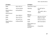
AC Adapter Width Depth Weight (without cables) 90 W (E-Series) Height Width Depth Weight (without cables) 64 mm (2.51 in) 127.0 mm (5.0 in) 0.29 kg (0.64 lb) 16 mm (0.62 in) 70 mm (2.75 in) 147 mm (5.7 in) 0.345 kg (0.76 lb) Basic Specifications AC Adapter Temperature ranges: Operating Storage 0° to 35°C (32° to 95°F) -40° to 65°C (-40° to 149°F) Physical Height Width 22.5 mm to 37.2 mm (0.88 in to 1.46 in) 319.3 mm (12.57 in) Depth Weight (with 6-cell battery): Configurable to less than 236.15 mm (9.29 in) 2.2 kg (4.9 lb) 57
AC Adapter Width Depth Weight (without cables) 90 W (E-Series) Height Width Depth Weight (without cables) 64 mm (2.51 in) 127.0 mm (5.0 in) 0.29 kg (0.64 lb) 16 mm (0.62 in) 70 mm (2.75 in) 147 mm (5.7 in) 0.345 kg (0.76 lb) Basic Specifications AC Adapter Temperature ranges: Operating Storage 0° to 35°C (32° to 95°F) -40° to 65°C (-40° to 149°F) Physical Height Width 22.5 mm to 37.2 mm (0.88 in to 1.46 in) 319.3 mm (12.57 in) Depth Weight (with 6-cell battery): Configurable to less than 236.15 mm (9.29 in) 2.2 kg (4.9 lb) 57
Owner's Manual (PDF)
Page 3
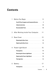
Contents 1 Before You Begin 9 Turn Off Your Computer and Connected Devices . . . . . 9 Safety Instructions 10 Recommended Tools 10 2 After Working Inside Your Computer . . . . 11 3 Base Cover 13 Removing the Base Cover 13 Replacing the Base Cover 14 4 Power-Light Board 15 Prerequisites 15 Removing the Power-Light Board 15 Replacing the Power-Light Board 16 Postrequisites 16 5 Battery 17 Prerequisites 17 Contents 3
Contents 1 Before You Begin 9 Turn Off Your Computer and Connected Devices . . . . . 9 Safety Instructions 10 Recommended Tools 10 2 After Working Inside Your Computer . . . . 11 3 Base Cover 13 Removing the Base Cover 13 Replacing the Base Cover 14 4 Power-Light Board 15 Prerequisites 15 Removing the Power-Light Board 15 Replacing the Power-Light Board 16 Postrequisites 16 5 Battery 17 Prerequisites 17 Contents 3
Owner's Manual (PDF)
Page 7
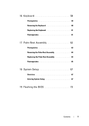
16 Keyboard 59 Prerequisites 59 Removing the Keyboard 60 Replacing the Keyboard 61 Postrequisites 61 17 Palm-Rest Assembly 63 Prerequisites 63 Removing the Palm-Rest Assembly 64 Replacing the Palm-Rest Assembly 64 Postrequisites 65 18 System Setup 67 Overview 67 Entering System Setup 67 19 Flashing the BIOS 73 Contents 7
16 Keyboard 59 Prerequisites 59 Removing the Keyboard 60 Replacing the Keyboard 61 Postrequisites 61 17 Palm-Rest Assembly 63 Prerequisites 63 Removing the Palm-Rest Assembly 64 Replacing the Palm-Rest Assembly 64 Postrequisites 65 18 System Setup 67 Overview 67 Entering System Setup 67 19 Flashing the BIOS 73 Contents 7
Owner's Manual (PDF)
Page 16
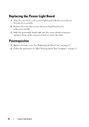
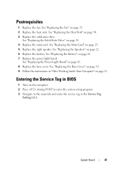
See "Replacing the Base Cover" on page 14. 2 Follow the instructions in "After Working Inside Your Computer" on the connector latch to the palm-rest assembly. 3 Slide the power-light board cable into the system-board connector and press down on page 11. 16 Power-Light Board Postrequisites 1 Replace the base cover. Replacing the Power-Light Board 1 Align the screw hole on the power-light board with the screw hole on the palm-rest assembly. 2 Replace the screw that secures the power-light board to secure the cable.
See "Replacing the Base Cover" on page 14. 2 Follow the instructions in "After Working Inside Your Computer" on the connector latch to the palm-rest assembly. 3 Slide the power-light board cable into the system-board connector and press down on page 11. 16 Power-Light Board Postrequisites 1 Replace the base cover. Replacing the Power-Light Board 1 Align the screw hole on the power-light board with the screw hole on the palm-rest assembly. 2 Replace the screw that secures the power-light board to secure the cable.
Owner's Manual (PDF)
Page 18
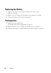
Postrequisites 1 Replace the power-light board. See "Replacing the Base Cover" on page 14. 3 Follow the instructions in "After Working Inside Your Computer" on the palm-rest assembly. 2 Replace the screws that secure the battery to the palm-rest assembly. 3 Connect the battery cable to the system-board. Replacing the Battery 1 Align the screw holes on the battery with the screw holes on page 11. 18 Battery See "Replacing the Power-Light Board" on page 16. 2 Replace the base cover.
Postrequisites 1 Replace the power-light board. See "Replacing the Base Cover" on page 14. 3 Follow the instructions in "After Working Inside Your Computer" on the palm-rest assembly. 2 Replace the screws that secure the battery to the palm-rest assembly. 3 Connect the battery cable to the system-board. Replacing the Battery 1 Align the screw holes on the battery with the screw holes on page 11. 18 Battery See "Replacing the Power-Light Board" on page 16. 2 Replace the base cover.
Owner's Manual (PDF)
Page 22
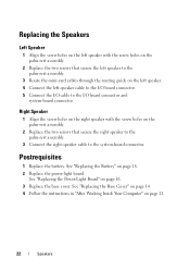
.... 4 Connect the left-speaker cable to the I/O board connector. 5 Connect the I /O board connector and system-board connector. See "Replacing the Power-Light Board" on page 16. 3 Replace the base cover.
.... 4 Connect the left-speaker cable to the I/O board connector. 5 Connect the I /O board connector and system-board connector. See "Replacing the Power-Light Board" on page 16. 3 Replace the base cover.
Owner's Manual (PDF)
Page 26
See "Replacing the Base Cover" on page 14. 4 Follow the instructions in "After Working Inside Your Computer" on page 16. 3 Replace the base cover. See "Replacing the Power-Light Board" on page 11. 26 Wireless Mini-Card Postrequisites 1 Replace the right speaker. See "Replacing the Battery" on page 22. 1 Replace the battery. See "Replacing the Speakers" on page 18. 2 Replace the power-light board.
See "Replacing the Base Cover" on page 14. 4 Follow the instructions in "After Working Inside Your Computer" on page 16. 3 Replace the base cover. See "Replacing the Power-Light Board" on page 11. 26 Wireless Mini-Card Postrequisites 1 Replace the right speaker. See "Replacing the Battery" on page 22. 1 Replace the battery. See "Replacing the Speakers" on page 18. 2 Replace the power-light board.
Owner's Manual (PDF)
Page 28
See "Replacing the Battery" on page 16. 3 Replace the base cover. See "Replacing the Base Cover" on page 14. 4 Follow the instructions in the system-board connector. Postrequisites 1 Replace the battery. See "...
See "Replacing the Battery" on page 16. 3 Replace the base cover. See "Replacing the Base Cover" on page 14. 4 Follow the instructions in the system-board connector. Postrequisites 1 Replace the battery. See "...
Owner's Manual (PDF)
Page 30
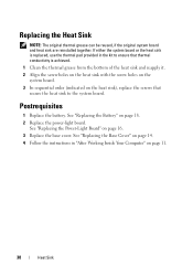
... that secure the heat sink to ensure that thermal conductivity is replaced, use the thermal pad provided in "After Working Inside Your Computer" on page 16. 3 Replace the base cover. If either the system board or the heat sink is achieved. 1 Clean the thermal grease from the bottom of the heat...
... that secure the heat sink to ensure that thermal conductivity is replaced, use the thermal pad provided in "After Working Inside Your Computer" on page 16. 3 Replace the base cover. If either the system board or the heat sink is achieved. 1 Clean the thermal grease from the bottom of the heat...
Owner's Manual (PDF)
Page 33
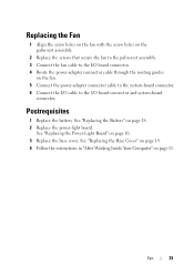
See "Replacing the Base Cover" on page 14. 4 Follow the instructions in "After Working Inside Your Computer" on page 16. 3 Replace the base cover. Postrequisites 1 Replace the battery. Fan 33 See "Replacing the Power-Light Board" on page 11. See "Replacing the Battery" on the ...
See "Replacing the Base Cover" on page 14. 4 Follow the instructions in "After Working Inside Your Computer" on page 16. 3 Replace the base cover. Postrequisites 1 Replace the battery. Fan 33 See "Replacing the Power-Light Board" on page 11. See "Replacing the Battery" on the ...
Owner's Manual (PDF)
Page 38
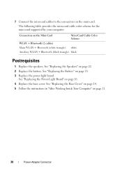
... mini-card supported by your computer. See "Replacing the Base Cover" on page 14. 5 Follow the instructions in "After Working Inside Your Computer" on page 16. 4 Replace the base cover. See "Replacing the Battery" on page 22. 2 Replace the battery. See "Replacing the Speakers" on page 18. 3 Replace the power-light...
... mini-card supported by your computer. See "Replacing the Base Cover" on page 14. 5 Follow the instructions in "After Working Inside Your Computer" on page 16. 4 Replace the base cover. See "Replacing the Battery" on page 22. 2 Replace the battery. See "Replacing the Speakers" on page 18. 3 Replace the power-light...
Owner's Manual (PDF)
Page 41
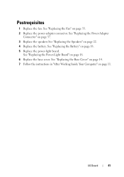
See "Replacing the Battery" on page 33. 2 Replace the power-adapter connector. See "Replacing the Fan" on page 18. 5 Replace the power-light board. See "Replacing the Power-Light Board" on page 11. See "Replacing the Base Cover" on page 14. 7 Follow the instructions in "After Working Inside Your Computer" on page 16. 6 Replace the base cover. Postrequisites 1 Replace the fan. See "Replacing the Power-Adapter Connector" on page 37. 3 Replace the speakers See "Replacing the Speakers" on page 22. 4 Replace the battery. I/O Board 41
See "Replacing the Battery" on page 33. 2 Replace the power-adapter connector. See "Replacing the Fan" on page 18. 5 Replace the power-light board. See "Replacing the Power-Light Board" on page 11. See "Replacing the Base Cover" on page 14. 7 Follow the instructions in "After Working Inside Your Computer" on page 16. 6 Replace the base cover. Postrequisites 1 Replace the fan. See "Replacing the Power-Adapter Connector" on page 37. 3 Replace the speakers See "Replacing the Speakers" on page 22. 4 Replace the battery. I/O Board 41
Owner's Manual (PDF)
Page 47
... Power-Light Board" on page 11. See "Replacing the Base Cover" on page 14. 9 Follow the instructions in "After Working Inside Your Computer" on page 16. 8 Replace the base cover. See "Replacing the Speakers" on page 30. 3 Replace the solid-state drive. See "Replacing the Heat Sink" on page 22. 6 Replace...
... Power-Light Board" on page 11. See "Replacing the Base Cover" on page 14. 9 Follow the instructions in "After Working Inside Your Computer" on page 16. 8 Replace the base cover. See "Replacing the Speakers" on page 30. 3 Replace the solid-state drive. See "Replacing the Heat Sink" on page 22. 6 Replace...
Owner's Manual (PDF)
Page 51
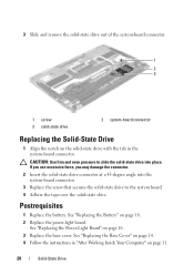
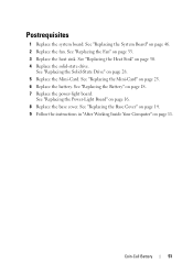
..." on page 30. 4 Replace the solid-state drive. See "Replacing the Heat Sink" on page 25. 6 Replace the battery. See "Replacing the Battery" on page 16. 8 Replace the base cover. See "Replacing the Power-Light Board" on page 18. 7 Replace the power-light board. See "Replacing the Base Cover" on page...
..." on page 30. 4 Replace the solid-state drive. See "Replacing the Heat Sink" on page 25. 6 Replace the battery. See "Replacing the Battery" on page 16. 8 Replace the base cover. See "Replacing the Power-Light Board" on page 18. 7 Replace the power-light board. See "Replacing the Base Cover" on page...
Owner's Manual (PDF)
Page 57
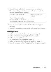
... page 11. Postrequisites 1 Replace the speakers. See "Replacing the Base Cover" on page 14. 5 Follow the instructions in "After Working Inside Your Computer" on page 16. 4 Replace the base cover. See "Replacing the Speakers" on page 18. 3 Replace the power-light board. 6 Connect the mini-card cables to the system-board...
... page 11. Postrequisites 1 Replace the speakers. See "Replacing the Base Cover" on page 14. 5 Follow the instructions in "After Working Inside Your Computer" on page 16. 4 Replace the base cover. See "Replacing the Speakers" on page 18. 3 Replace the power-light board. 6 Connect the mini-card cables to the system-board...
Owner's Manual (PDF)
Page 59
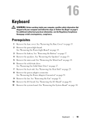
... the Mini-Card" on page 17. 4 Remove the speakers. See "Removing the System Board" on page 13. 2 Remove the power-light board. See "Removing the Base Cover" on page 44. Keyboard 59 16 Keyboard WARNING: Before working inside your computer, read the safety information that shipped with your computer and follow... See "Removing the Heat Sink" on page 19. 5 Remove the mini-card. For additional safety best practices information, see the Regulatory Compliance Homepage at dell.com/regulatory_compliance. See "Removing the Speakers" on page 29. 8 Remove the power-adapter connector.
... the Mini-Card" on page 17. 4 Remove the speakers. See "Removing the System Board" on page 13. 2 Remove the power-light board. See "Removing the Base Cover" on page 44. Keyboard 59 16 Keyboard WARNING: Before working inside your computer, read the safety information that shipped with your computer and follow... See "Removing the Heat Sink" on page 19. 5 Remove the mini-card. For additional safety best practices information, see the Regulatory Compliance Homepage at dell.com/regulatory_compliance. See "Removing the Speakers" on page 29. 8 Remove the power-adapter connector.
Owner's Manual (PDF)
Page 61
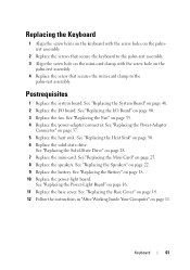
... secures the mini-card clamp to the palm-rest assembly. 3 Align the screw hole on the mini-card clamp with the screw hole on page 16. 11 Replace the base cover.
... secures the mini-card clamp to the palm-rest assembly. 3 Align the screw hole on the mini-card clamp with the screw hole on page 16. 11 Replace the base cover.


