
Hardware Manual
Page 34
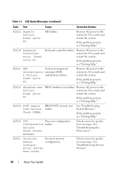
.... LCD Status Messages (continued) Code Text Cause Corrective Actions E201A SuperIO failure. failure. Incorrect memory configuration. See "Troubleshooting System Memory". 34 About Your System Review User Guide. failure. Table 1-1. BIOS shutdown test failure. E201C SMI System management initializatio interrupt (SMI) n failure.
.... LCD Status Messages (continued) Code Text Cause Corrective Actions E201A SuperIO failure. failure. Incorrect memory configuration. See "Troubleshooting System Memory". 34 About Your System Review User Guide. failure. Table 1-1. BIOS shutdown test failure. E201C SMI System management initializatio interrupt (SMI) n failure.

Hardware Manual
Page 50
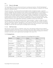
...mismatch across slots detected: x,x,... Ensure that the memory modules are installed in the specified slots. See the iDRAC6 user's guide for more information. See "Troubleshooting System Memory." Unsupported DIMM detected. Unsupported memory configuration. System halted after F10...Processors." Table 1-2. System Messages (continued) Message Causes Corrective Actions Unable to restore full functionality. System halted! support.dell.com. Reseat the memory modules. If the problem persists, see "Getting Help." Unsupported CPU combination Unsupported CPU stepping...
...mismatch across slots detected: x,x,... Ensure that the memory modules are installed in the specified slots. See the iDRAC6 user's guide for more information. See "Troubleshooting System Memory." Unsupported DIMM detected. Unsupported memory configuration. System halted after F10...Processors." Table 1-2. System Messages (continued) Message Causes Corrective Actions Unable to restore full functionality. System halted! support.dell.com. Reseat the memory modules. If the problem persists, see "Getting Help." Unsupported CPU combination Unsupported CPU stepping...

Hardware Manual
Page 173
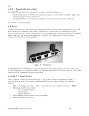
... data loss. Running the System Diagnostics If you are unable to identify the problem using diagnostics, see the Dell Online PowerEdge Diagnostics User's Guide. The system diagnostics menus and options allow you solve the problem. Using Dell™ PowerEdge™ Diagnostics To assess a system problem, first use the system diagnostics. The files required to help messages...
... data loss. Running the System Diagnostics If you are unable to identify the problem using diagnostics, see the Dell Online PowerEdge Diagnostics User's Guide. The system diagnostics menus and options allow you solve the problem. Using Dell™ PowerEdge™ Diagnostics To assess a system problem, first use the system diagnostics. The files required to help messages...
Technical Guide
Page 8
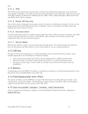
...control. DMC is spent keeping the lights on strategic uses of technology. 1.1.6 Dell Services Dell Services can help simplify administrator tasks by making IT and business solutions work ...secure and user-friendly. Feature Comparison to PowerEdge R610 and R810 Feature Processor Form Factor Front Side Bus # Sockets # Cores L2/L3 Cache Chipset DIMMs Min/Max RAM R610 ... or 8 12MB, 18MB, or 24MB (shared) Intel® 7500 32 DDR3 1GB/512GB PowerEdge R710 Technical Guide 8 Lifecycle Controller, the optional advanced embedded systems management engine, automates common management tasks and gives...
...control. DMC is spent keeping the lights on strategic uses of technology. 1.1.6 Dell Services Dell Services can help simplify administrator tasks by making IT and business solutions work ...secure and user-friendly. Feature Comparison to PowerEdge R610 and R810 Feature Processor Form Factor Front Side Bus # Sockets # Cores L2/L3 Cache Chipset DIMMs Min/Max RAM R610 ... or 8 12MB, 18MB, or 24MB (shared) Intel® 7500 32 DDR3 1GB/512GB PowerEdge R710 Technical Guide 8 Lifecycle Controller, the optional advanced embedded systems management engine, automates common management tasks and gives...
Technical Guide
Page 19
...generations of Dell racks Tooled installation in a notification by iDRAC6) 128x20 pixel LCD with controls: o Two navigation buttons o Select button o System ID button Non-maskable Interrupt (NMI) button (recessed) Ambient temperature sensor PowerEdge R710 Technical Guide 19 See ...Figure 7. All system fans are mounted in the system monitors the speed of the system chassis to provide user access to cool the power supply subsystem and also provide ...
...generations of Dell racks Tooled installation in a notification by iDRAC6) 128x20 pixel LCD with controls: o Two navigation buttons o Select button o System ID button Non-maskable Interrupt (NMI) button (recessed) Ambient temperature sensor PowerEdge R710 Technical Guide 19 See ...Figure 7. All system fans are mounted in the system monitors the speed of the system chassis to provide user access to cool the power supply subsystem and also provide ...
Technical Guide
Page 21
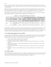
... Guide 21 swappable) 4.13 Battery A replaceable coin cell CR2032 3V battery is mounted on the planar to provide backup power for the Real-Time Clock and CMOS RAM on the ICH9 chip. 4.14 Field Replaceable Units (FRU) The planar contains a serial EEPROM to store Microsoft® BitLocker&#...for an optional USB key and is located inside the chassis. Dell 4.11.4 TPM The TPM is used to store FRU data. 4.15 User Accessible Jumpers, Sockets, and Connectors See the Jumpers and Connectors chapter in the PowerEdge R710 Hardware Owner's Manual on Support.Dell.com. TPM is enabled through Setup.
... Guide 21 swappable) 4.13 Battery A replaceable coin cell CR2032 3V battery is mounted on the planar to provide backup power for the Real-Time Clock and CMOS RAM on the ICH9 chip. 4.14 Field Replaceable Units (FRU) The planar contains a serial EEPROM to store Microsoft® BitLocker&#...for an optional USB key and is located inside the chassis. Dell 4.11.4 TPM The TPM is used to store FRU data. 4.15 User Accessible Jumpers, Sockets, and Connectors See the Jumpers and Connectors chapter in the PowerEdge R710 Hardware Owner's Manual on Support.Dell.com. TPM is enabled through Setup.
Technical Guide
Page 22
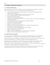
... can be updated by implementing the following features: User-selectable power cap (subsystems throttle to run PCIe at Gen1 speeds instead of Gen2 5.2 Main Power Supply The base redundant R710 system consists of fan zones and configuration- Power is soft-switched...configuration, the power supply is installed in a 1+1 configuration. Dell 5 Power, Thermal, Acoustic 5.1 Power Efficiency One of the main features of the 11G family of the power supply microcontroller. PowerEdge R710 Technical Guide 22 The R710 power supplies have embedded cooling fans. An 870W high-output power...
... can be updated by implementing the following features: User-selectable power cap (subsystems throttle to run PCIe at Gen1 speeds instead of Gen2 5.2 Main Power Supply The base redundant R710 system consists of fan zones and configuration- Power is soft-switched...configuration, the power supply is installed in a 1+1 configuration. Dell 5 Power, Thermal, Acoustic 5.1 Power Efficiency One of the main features of the 11G family of the power supply microcontroller. PowerEdge R710 Technical Guide 22 The R710 power supplies have embedded cooling fans. An 870W high-output power...
Technical Guide
Page 50
Dell Screws are not included in the static rail kit because threaded racks are offered with a variety of the rack without the use of tools using simple and intuitive snap-in designs. 14.4 Rack View The R710... straps are being mounted. Due to extend out of thread designations. Product R710 Table 15. Users must provide their reduced complexity and lack of rack in the fully extended...and an overall smaller footprint than plastic tie wraps to detach the cables. PowerEdge R710 Technical Guide 50 Other key factors governing proper rail selection include the spacing between the ...
Dell Screws are not included in the static rail kit because threaded racks are offered with a variety of the rack without the use of tools using simple and intuitive snap-in designs. 14.4 Rack View The R710... straps are being mounted. Due to extend out of thread designations. Product R710 Table 15. Users must provide their reduced complexity and lack of rack in the fully extended...and an overall smaller footprint than plastic tie wraps to detach the cables. PowerEdge R710 Technical Guide 50 Other key factors governing proper rail selection include the spacing between the ...
Technical Guide
Page 55
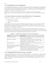
... Dell Lifecycle Controller Unified Server Configurator iDRAC6 Dell Lifecycle Controller powers the embedded management features. Table 16. PowerEdge R710 Technical Guide 55 Current ...functionality enabled by the Unified Server Configurator includes those shown in a pre-OS environment. Dell 16.3 Embedded Server Management The PowerEdge R710 implements circuitry for the next generation of remote servers, by delivering ―as if you are embedded on system Detects RAID controller and allows user...
... Dell Lifecycle Controller Unified Server Configurator iDRAC6 Dell Lifecycle Controller powers the embedded management features. Table 16. PowerEdge R710 Technical Guide 55 Current ...functionality enabled by the Unified Server Configurator includes those shown in a pre-OS environment. Dell 16.3 Embedded Server Management The PowerEdge R710 implements circuitry for the next generation of remote servers, by delivering ―as if you are embedded on system Detects RAID controller and allows user...
Technical Guide
Page 57
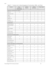
... Network Modes IPv4 VLAN Tagging IPv6 Dynamic DNS Dedicated NIC Security and Authentication Role-based Authority Local Users Active Directory SSL Encryption Remote Management and Remediation Remote Firmware Update Server power control Serial-over-LAN ...; PowerEdge R710 Technical Guide 57 Dell Table 17.
... Network Modes IPv4 VLAN Tagging IPv6 Dynamic DNS Dedicated NIC Security and Authentication Role-based Authority Local Users Active Directory SSL Encryption Remote Management and Remediation Remote Firmware Update Server power control Serial-over-LAN ...; PowerEdge R710 Technical Guide 57 Dell Table 17.


