
Hardware Manual
Page 13
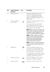
The power button controls the DC power supply output to do so by qualified support personnel or by the operating system's documentation. About Your System 13 NOTE: To force an ungraceful shutdown, press and hold the power button for system ...
The power button controls the DC power supply output to do so by qualified support personnel or by the operating system's documentation. About Your System 13 NOTE: To force an ungraceful shutdown, press and hold the power button for system ...
Hardware Manual
Page 14
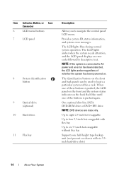
... and the system status indicator on the back flash blue until one of the buttons is connected to six 3.5-inch hot-swappable without flex bay Supports one half-height tape backup unit (not present on chassis with flex bay Up to AC power and an error has been detected, the LCD...
... and the system status indicator on the back flash blue until one of the buttons is connected to six 3.5-inch hot-swappable without flex bay Supports one half-height tape backup unit (not present on chassis with flex bay Up to AC power and an error has been detected, the LCD...
Hardware Manual
Page 24
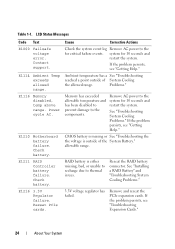
... the the voltage is either missing, bad, or unable to recharge due to the system for 10 seconds and restart the system. allowable range. Contact support. E1114 Ambient Temp exceeds allowed range. Cause Corrective Actions Check the system event log Remove AC power to the components. system for 10 seconds and...
... the the voltage is either missing, bad, or unable to recharge due to the system for 10 seconds and restart the system. allowable range. Contact support. E1114 Ambient Temp exceeds allowed range. Cause Corrective Actions Check the system event log Remove AC power to the components. system for 10 seconds and...

Hardware Manual
Page 25
... cycle AC. A power fault was detected Remove AC power to the system for 10 seconds and processor(s). If the problem persists, see "Getting Help." Call support. Reseat CPU. E122A CPU # VTT Regulator failure. Specified processor VTT Reseat the processor(s). One of the memory Regulator # regulators has failed. E1310 Fan ## RPM exceeding...
... cycle AC. A power fault was detected Remove AC power to the system for 10 seconds and processor(s). If the problem persists, see "Getting Help." Call support. Reseat CPU. E122A CPU # VTT Regulator failure. Specified processor VTT Reseat the processor(s). One of the memory Regulator # regulators has failed. E1310 Fan ## RPM exceeding...
Hardware Manual
Page 37
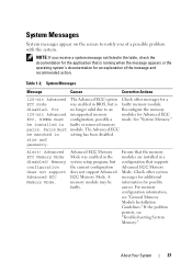
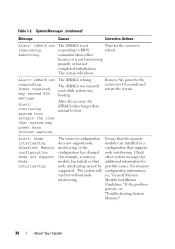
... About Your System 37 be installed in a configuration that is faulty memory module. Pairs must configuration, possibly a mode. Memory configuration does not support Advanced ECC Memory Mode. Table 1-2. Alert! A memory module may be matched in the table, check the documentation for the application that... ECC Memory Mode. Check other messages for a ECC mode was enabled in BIOS, but the current configuration does not support Advanced ECC Memory Mode. If the problem persists, see "General Memory Module Installation Guidelines." For no longer valid due to notify you ...
... About Your System 37 be installed in a configuration that is faulty memory module. Pairs must configuration, possibly a mode. Memory configuration does not support Advanced ECC Memory Mode. Table 1-2. Alert! A memory module may be matched in the table, check the documentation for the application that... ECC Memory Mode. Check other messages for a ECC mode was enabled in BIOS, but the current configuration does not support Advanced ECC Memory Mode. If the problem persists, see "General Memory Module Installation Guidelines." For no longer valid due to notify you ...
Hardware Manual
Page 38
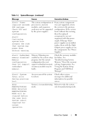
... (continued) Message Causes Corrective Actions Alert! iDRAC6 not responding. iDRAC6 not responding. Continuing system boot accepts the risk that supports node interleaving. The iDRAC6 is not functioning properly or has not completed initialization. Remove AC power to reboot. Check other ...system messages for additional information for example, a memory module has failed) so that node interleaving cannot be supported. Node Interleaving disabled! Ensure that the memory modules are installed in a configuration that system may exceed PSU wattage. The iDRAC6...
... (continued) Message Causes Corrective Actions Alert! iDRAC6 not responding. iDRAC6 not responding. Continuing system boot accepts the risk that supports node interleaving. The iDRAC6 is not functioning properly or has not completed initialization. Remove AC power to reboot. Check other ...system messages for additional information for example, a memory module has failed) so that node interleaving cannot be supported. Node Interleaving disabled! Ensure that the memory modules are installed in a configuration that system may exceed PSU wattage. The iDRAC6...
Hardware Manual
Page 39
... other system messages for additional information for failure. System is in the system setup program, but the current configuration does not support redundant memory. See "Power Supplies." Check the memory modules for possible causes. An error caused the system to the previous configuration...memory modules, and expansion cards may be cleared before the next boot. Memory configuration does not support redundant memory. If Energy Smart power supplies are not supported with the High Output power supplies to take the system mode. The system configuration of manufacturing mode...
... other system messages for additional information for failure. System is in the system setup program, but the current configuration does not support redundant memory. See "Power Supplies." Check the memory modules for possible causes. An error caused the system to the previous configuration...memory modules, and expansion cards may be cleared before the next boot. Memory configuration does not support redundant memory. If Energy Smart power supplies are not supported with the High Output power supplies to take the system mode. The system configuration of manufacturing mode...
Hardware Manual
Page 44
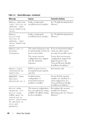
... installed. Memory write/read failure at address, read value expecting value Faulty or improperly See "Troubleshooting System installed memory modules. Ensure that your memory configuration supports the higher frequency. MEMTEST lane failure detected on x Invalid memory configuration. Memory." The memory frequency may...
... installed. Memory write/read failure at address, read value expecting value Faulty or improperly See "Troubleshooting System installed memory modules. Ensure that your memory configuration supports the higher frequency. MEMTEST lane failure detected on x Invalid memory configuration. Memory." The memory frequency may...

Hardware Manual
Page 50
System halted after F10 keystroke because System Services image is not supported Install a supported processor by the system. See "Troubleshooting System Memory." Memory modules are installed in a valid configuration. See the ...x,x,... Ensure that the memory modules are mismatched in protected mode Improperly seated memory modules or faulty keyboard/mouse controller chip. System halted! support.dell.com. The system will run but with the specified memory module disabled. Table 1-2. Reseat the memory modules. Unsupported CPU combination Unsupported ...
System halted after F10 keystroke because System Services image is not supported Install a supported processor by the system. See "Troubleshooting System Memory." Memory modules are installed in a valid configuration. See the ...x,x,... Ensure that the memory modules are mismatched in protected mode Improperly seated memory modules or faulty keyboard/mouse controller chip. System halted! support.dell.com. The system will run but with the specified memory module disabled. Table 1-2. Reseat the memory modules. Unsupported CPU combination Unsupported ...

Hardware Manual
Page 52
... and memory set to minimum frequencies to use the components. See "Power Supplies." system at the same time. Ensure that the memory modules are not supported with this warning, configuration. Warning! The memory configuration is : Invalid memory configuration. The system will component(s) are installed in the system. If the problem persists... Module Installation Guidelines." boots without this power supply. reboot. Warning! modules, and expansion the system to the previous Check PSU and cards may not be supported configuration.
... and memory set to minimum frequencies to use the components. See "Power Supplies." system at the same time. Ensure that the memory modules are not supported with this warning, configuration. Warning! The memory configuration is : Invalid memory configuration. The system will component(s) are installed in the system. If the problem persists... Module Installation Guidelines." boots without this power supply. reboot. Warning! modules, and expansion the system to the previous Check PSU and cards may not be supported configuration.

Hardware Manual
Page 54
... your rack solution describes how to the operating system, system management software, system updates, and system components that provides documentation and tools for updates on support.dell.com and read the updates first because they often supersede information in other documents. 54 About Your System
... your rack solution describes how to the operating system, system management software, system updates, and system components that provides documentation and tools for updates on support.dell.com and read the updates first because they often supersede information in other documents. 54 About Your System

Hardware Manual
Page 55
...® Windows Server® 2008 x64 version) to boot the operating system from the BIOS boot mode. DOS and 32-bit operating systems do not support UEFI and can : • Change the NVRAM settings after you add or remove hardware • View the system hardware configuration • Enable or disable integrated...
...® Windows Server® 2008 x64 version) to boot the operating system from the BIOS boot mode. DOS and 32-bit operating systems do not support UEFI and can : • Change the NVRAM settings after you add or remove hardware • View the system hardware configuration • Enable or disable integrated...
Hardware Manual
Page 59
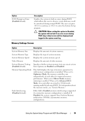
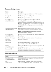
..., the system will be displayed and logged in 128-bit mode running multi-bit advanced ECC. If Disabled, the system supports Non-Uniform Memory architecture (NUMA) (asymmetric) memory configurations. When set to Mirror Mode, memory mirroring is enabled. CAUTION:... When setting this field is Enabled, memory interleaving is supported if a symmetric memory configuration is installed. Memory Settings Screen Option Description System Memory Size Displays the amount of system memory....
..., the system will be displayed and logged in 128-bit mode running multi-bit advanced ECC. If Disabled, the system supports Non-Uniform Memory architecture (NUMA) (asymmetric) memory configurations. When set to Mirror Mode, memory mirroring is enabled. CAUTION:... When setting this field is Enabled, memory interleaving is supported if a symmetric memory configuration is installed. Memory Settings Screen Option Description System Memory Size Displays the amount of system memory....
Hardware Manual
Page 60
... the processor bus speed. Number of Cores per Processor (All default) If set to All, the maximum number of each processor is supported by the BIOS. If this feature if your system will not be running virtualization software. Execute Disable (Enabled default) Enables or disables ...disables the controller. C States (Enabled default) When set to Enabled, the processor(s) can operate in each processor. Auto enables BIOS support for the device. 60 Using the System Setup Program and UEFI Boot Manager Turbo Mode If Turbo Boost Technology is enabled. Off disables BIOS...
... the processor bus speed. Number of Cores per Processor (All default) If set to All, the maximum number of each processor is supported by the BIOS. If this feature if your system will not be running virtualization software. Execute Disable (Enabled default) Enables or disables ...disables the controller. C States (Enabled default) When set to Enabled, the processor(s) can operate in each processor. Auto enables BIOS support for the device. 60 Using the System Setup Program and UEFI Boot Manager Turbo Mode If Turbo Boost Technology is enabled. Off disables BIOS...
Hardware Manual
Page 61
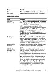
..., and USB Flash Drive Emulation Type fields. Using the System Setup Program and UEFI Boot Manager 61 If the system operating system supports Unified Extensible Firmware Interface, you install a device in the same boot mode. A device installed in the system during system startup....emulate a hard drive. Determines the emulation type for the device attached to Floppy. Option Port B (Off default) Description Auto enables BIOS support for a USB flash drive. Boot Settings Screen Option Boot Mode (BIOS default) Boot Sequence Hard-Disk Drive Sequence USB Flash Drive Emulation ...
..., and USB Flash Drive Emulation Type fields. Using the System Setup Program and UEFI Boot Manager 61 If the system operating system supports Unified Extensible Firmware Interface, you install a device in the same boot mode. A device installed in the system during system startup....emulate a hard drive. Determines the emulation type for the device attached to Floppy. Option Port B (Off default) Description Auto enables BIOS support for a USB flash drive. Boot Settings Screen Option Boot Mode (BIOS default) Boot Sequence Hard-Disk Drive Sequence USB Flash Drive Emulation ...
Hardware Manual
Page 62
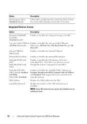
...USB Ports Enables or disables the user-accessible USB ports. (All Ports On default) Options are Enabled, Enabled with PXE, Enabled with PXE; PXE support allows the system to boot after 30 seconds. NOTE: Some NIC features may also be accessed through the system's management controller.) Embedded... Gb NICx (NIC1 default: Enabled with iSCSI Boot, and Disabled. Option Boot Sequence Retry (Disabled default) Description If this field is enabled and the ...
...USB Ports Enables or disables the user-accessible USB ports. (All Ports On default) Options are Enabled, Enabled with PXE, Enabled with PXE; PXE support allows the system to boot after 30 seconds. NOTE: Some NIC features may also be accessed through the system's management controller.) Embedded... Gb NICx (NIC1 default: Enabled with iSCSI Boot, and Disabled. Option Boot Sequence Retry (Disabled default) Description If this field is enabled and the ...

Hardware Manual
Page 63
NOTE: This feature is usable only with Console Redirection via COM1, On with operating systems that support WDAT implementations of the Advanced Configuration and Power Interface (ACPI) 3.0b specification. Enables or disables BIOS support for a given device, or select Default to allow the BIOS to initialize the timer. Using the System Setup Program...
NOTE: This feature is usable only with Console Redirection via COM1, On with operating systems that support WDAT implementations of the Advanced Configuration and Power Interface (ACPI) 3.0b specification. Enables or disables BIOS support for a given device, or select Default to allow the BIOS to initialize the timer. Using the System Setup Program...

Hardware Manual
Page 67
... lose all TPM contents are Immediate, Random (a random value of 30 to 240 seconds), or a user-defined value of 30 to do so by qualified support personnel or by the operating system's documentation. This option prevents booting to exit the System Setup program; When set to Setup Using the System Setup...
... lose all TPM contents are Immediate, Random (a random value of 30 to 240 seconds), or a user-defined value of 30 to do so by qualified support personnel or by the operating system's documentation. This option prevents booting to exit the System Setup program; When set to Setup Using the System Setup...
Hardware Manual
Page 75
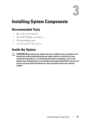
... Torx drivers Inside the System CAUTION: Many repairs may only be done by the online or telephone service and support team. Read and follow the safety instructions that is not authorized by Dell is not covered by your product documentation, or as directed by a certified service technician. Installing System Components 75 You...
... Torx drivers Inside the System CAUTION: Many repairs may only be done by the online or telephone service and support team. Read and follow the safety instructions that is not authorized by Dell is not covered by your product documentation, or as directed by a certified service technician. Installing System Components 75 You...
Hardware Manual
Page 79
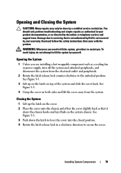
... done by yourself. Damage due to secure the cover. Read and follow the safety instructions that is not authorized by Dell is not covered by the online or telephone service and support team. WARNING: Whenever you need to lift the system, get others to lever the cover into the closed position. 4 Rotate...
... done by yourself. Damage due to secure the cover. Read and follow the safety instructions that is not authorized by Dell is not covered by the online or telephone service and support team. WARNING: Whenever you need to lift the system, get others to lever the cover into the closed position. 4 Rotate...


