
Hardware Manual
Page 3
Contents 1 About Your System 11 Accessing System Features During Startup 11 Front-Panel Features and Indicators 12 LCD Panel Features 15 Home Screen 16 Setup Menu 16 View Menu 17 Hard-Drive Indicator Patterns for RAID 18 Back Panel Features and Indicators 19 Power Indicator Codes 21 NIC Indicator Codes 22 LCD Status Messages 23 Viewing Status Messages 23 Removing LCD Status Messages 23 System Messages 37 Warning Messages 53 Diagnostics Messages 53 Alert Messages 53 Other Information You May Need 54 Contents 3
Contents 1 About Your System 11 Accessing System Features During Startup 11 Front-Panel Features and Indicators 12 LCD Panel Features 15 Home Screen 16 Setup Menu 16 View Menu 17 Hard-Drive Indicator Patterns for RAID 18 Back Panel Features and Indicators 19 Power Indicator Codes 21 NIC Indicator Codes 22 LCD Status Messages 23 Viewing Status Messages 23 Removing LCD Status Messages 23 System Messages 37 Warning Messages 53 Diagnostics Messages 53 Alert Messages 53 Other Information You May Need 54 Contents 3

Hardware Manual
Page 5
... Closing the System 79 Opening the System 79 Closing the System 79 Hard Drives 80 Mixed SAS/SATA Hard-Drive Configurations . . . 81 Removing a Hard-Drive Blank 81 Installing a Hard-Drive Blank 82 Removing a Hot-Swap Hard Drive 82 Installing a Hot-Swap Hard Drive 83 Removing a Hard Drive From a Hard-Drive Carrier 84 Installing a Hard Drive Into a Hard-Drive Carrier 84 Power Supplies 86 Removing a Power Supply 86 Replacing a Power Supply...
... Closing the System 79 Opening the System 79 Closing the System 79 Hard Drives 80 Mixed SAS/SATA Hard-Drive Configurations . . . 81 Removing a Hard-Drive Blank 81 Installing a Hard-Drive Blank 82 Removing a Hot-Swap Hard Drive 82 Installing a Hot-Swap Hard Drive 83 Removing a Hard Drive From a Hard-Drive Carrier 84 Installing a Hard Drive Into a Hard-Drive Carrier 84 Power Supplies 86 Removing a Power Supply 86 Replacing a Power Supply...
Hardware Manual
Page 9
... 162 Troubleshooting an Internal USB Memory Key . . . . . 163 Troubleshooting an Optical Drive 164 Troubleshooting a Tape Backup Unit 165 Troubleshooting a Hard Drive 166 Troubleshooting a Storage Controller 167 Troubleshooting Expansion Cards 168 Troubleshooting the Processor(s 170 5 Running the System Diagnostics . . . . . 173 Using Dell™ PowerEdge™ Diagnostics 173 System Diagnostics Features 173 When to Use the System...
... 162 Troubleshooting an Internal USB Memory Key . . . . . 163 Troubleshooting an Optical Drive 164 Troubleshooting a Tape Backup Unit 165 Troubleshooting a Hard Drive 166 Troubleshooting a Storage Controller 167 Troubleshooting Expansion Cards 168 Troubleshooting the Processor(s 170 5 Running the System Diagnostics . . . . . 173 Using Dell™ PowerEdge™ Diagnostics 173 System Diagnostics Features 173 When to Use the System...
Hardware Manual
Page 14
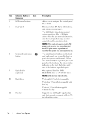
.... NOTE: DVD devices are data only. Up to eight 2.5-inch hot-swappable Up to four 3.5-inch hot-swappable with six 3.5inch hard-drive slots) 14 About Your System The LCD lights amber when the system needs attention, and the LCD panel displays an error code followed ...by descriptive text. Item Indicator, Button, or Icon Connector 6 LCD menu buttons 7 LCD panel 8 System identification button 9 Optical drive (optional) 10 Hard drives 11 Flex bay Description Allows you to six 3.5-inch hot-swappable without flex bay Supports one of the buttons is pushed again. When one...
.... NOTE: DVD devices are data only. Up to eight 2.5-inch hot-swappable Up to four 3.5-inch hot-swappable with six 3.5inch hard-drive slots) 14 About Your System The LCD lights amber when the system needs attention, and the LCD panel displays an error code followed ...by descriptive text. Item Indicator, Button, or Icon Connector 6 LCD menu buttons 7 LCD panel 8 System identification button 9 Optical drive (optional) 10 Hard drives 11 Flex bay Description Allows you to six 3.5-inch hot-swappable without flex bay Supports one of the buttons is pushed again. When one...
Hardware Manual
Page 18
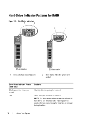
Drives are initialized after system power is applied. Hard-Drive Indicator Patterns for insertion or removal during this time. 18 About Your System Hard-Drive Indicators 1 2 1 2 3.5-in carrier 1 drive-activity indicator (green) 2.5-in carrier 2 drive-status indicator (green and amber) Drive-Status Indicator Pattern (RAID Only) Blinks green two times per second Off Condition Identify drive/preparing for removal Drive ready for insertion or removal NOTE: The drive status indicator remains off until all hard drives are not ready for RAID Figure 1-4.
Drives are initialized after system power is applied. Hard-Drive Indicator Patterns for insertion or removal during this time. 18 About Your System Hard-Drive Indicators 1 2 1 2 3.5-in carrier 1 drive-activity indicator (green) 2.5-in carrier 2 drive-status indicator (green and amber) Drive-Status Indicator Pattern (RAID Only) Blinks green two times per second Off Condition Identify drive/preparing for removal Drive ready for insertion or removal NOTE: The drive status indicator remains off until all hard drives are not ready for RAID Figure 1-4.
Hardware Manual
Page 31
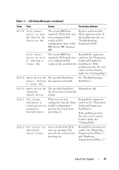
... configurations mismatch. See "Expansion Cards and ExpansionCard Risers." has been removed from Reconfigure. prevent the system from the Check drive. Check Riser. Reinstall the missing riser card(s). See "Replacing Expansion-Card Riser 1" and "Replacing Expansion-Card Riser 2." E1812 Hard drive ## The specified hard drive Information only. See "Troubleshooting a Hard Drive." E1810 Hard drive ## The specified hard drive fault. Review & clear SEL.
... configurations mismatch. See "Expansion Cards and ExpansionCard Risers." has been removed from Reconfigure. prevent the system from the Check drive. Check Riser. Reinstall the missing riser card(s). See "Replacing Expansion-Card Riser 1" and "Replacing Expansion-Card Riser 2." E1812 Hard drive ## The specified hard drive Information only. See "Troubleshooting a Hard Drive." E1810 Hard drive ## The specified hard drive fault. Review & clear SEL.
Hardware Manual
Page 45
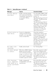
... SD Card," "Troubleshooting a USB Device," "Troubleshooting an Optical Drive," and "Troubleshooting a Hard Drive." If necessary, install the operating system on setting the order of boot devices. See your hard drive. PCI BIOS failed to install PCIe device BIOS (Option ROM)...Messages (continued) Message Causes Corrective Actions No boot device available Faulty or missing optical drive subsystem, hard drive, or hard-drive subsystem, or no operating system on Incorrect configuration hard drive settings in the specified slot number. Table 1-2. If the problem persists, see "...
... SD Card," "Troubleshooting a USB Device," "Troubleshooting an Optical Drive," and "Troubleshooting a Hard Drive." If necessary, install the operating system on setting the order of boot devices. See your hard drive. PCI BIOS failed to install PCIe device BIOS (Option ROM)...Messages (continued) Message Causes Corrective Actions No boot device available Faulty or missing optical drive subsystem, hard drive, or hard-drive subsystem, or no operating system on Incorrect configuration hard drive settings in the specified slot number. Table 1-2. If the problem persists, see "...
Hardware Manual
Page 46
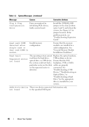
... About Your System See defective. "Troubleshooting a USB Device," "Troubleshooting an Optical Drive," or "Troubleshooting a Hard Drive" for jumper location. Invalid memory configuration. faulty system board. optical drive, or USB device, Ensure that the memory modules are properly or the requested sector... Configuration Error Error encountered in socket. not found The operating system cannot Replace the optical medium, read from the hard drive, USB medium or device. Quad rank DIMM detected after single rank or dual rank DIMM in initializing PCIe device;...
... About Your System See defective. "Troubleshooting a USB Device," "Troubleshooting an Optical Drive," or "Troubleshooting a Hard Drive" for jumper location. Invalid memory configuration. faulty system board. optical drive, or USB device, Ensure that the memory modules are properly or the requested sector... Configuration Error Error encountered in socket. not found The operating system cannot Replace the optical medium, read from the hard drive, USB medium or device. Quad rank DIMM detected after single rank or dual rank DIMM in initializing PCIe device;...
Hardware Manual
Page 47
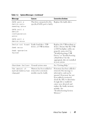
...SATA port is informative and can be faulty. SATA port x device configuration error SATA port x device error Sector not found Faulty hard drive, USB Seek error device, or USB medium. Ensure that the USB or SAS backplane cables are properly connected. Shutdown failure General ...USB medium or device. If memory has not been added or removed, check the SEL to the Replace the faulty drive. See "Getting Help." Table 1-2. About Your System 47 See "Troubleshooting a USB Device" or "Troubleshooting a Hard Drive" for the appropriate drive(s) installed in your system.
...SATA port is informative and can be faulty. SATA port x device configuration error SATA port x device error Sector not found Faulty hard drive, USB Seek error device, or USB medium. Ensure that the USB or SAS backplane cables are properly connected. Shutdown failure General ...USB medium or device. If memory has not been added or removed, check the SEL to the Replace the faulty drive. See "Getting Help." Table 1-2. About Your System 47 See "Troubleshooting a USB Device" or "Troubleshooting a Hard Drive" for the appropriate drive(s) installed in your system.
Hardware Manual
Page 53
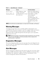
... System Diagnostics" for your system. Alert messages include information, status, warning, and failure messages for drive, temperature, fan, and power conditions. Warning Messages A warning message alerts you to a possible problem and prompts you that the USB, assembly, hard drive, or hard- System Messages (continued) Message Causes Corrective Actions Write fault Write fault on the...
... System Diagnostics" for your system. Alert messages include information, status, warning, and failure messages for drive, temperature, fan, and power conditions. Warning Messages A warning message alerts you to a possible problem and prompts you that the USB, assembly, hard drive, or hard- System Messages (continued) Message Causes Corrective Actions Write fault Write fault on the...
Hardware Manual
Page 61
...Boot Settings Screen Option Boot Mode (BIOS default) Boot Sequence Hard-Disk Drive Sequence USB Flash Drive Emulation Type (Auto default) Description CAUTION: Switching the boot mode could prevent the system from hard drives in the internal SD card slot will attempt to UEFI. If...will automatically emulate a hard drive. A device installed in the system during system startup. If Boot Mode is configured as a hard drive. Off disables BIOS support for the device attached to UEFI disables the Boot Sequence, Hard-Disk Drive Sequence, and USB Flash Drive Emulation Type fields....
...Boot Settings Screen Option Boot Mode (BIOS default) Boot Sequence Hard-Disk Drive Sequence USB Flash Drive Emulation Type (Auto default) Description CAUTION: Switching the boot mode could prevent the system from hard drives in the internal SD card slot will attempt to UEFI. If...will automatically emulate a hard drive. A device installed in the system during system startup. If Boot Mode is configured as a hard drive. Off disables BIOS support for the device attached to UEFI disables the Boot Sequence, Hard-Disk Drive Sequence, and USB Flash Drive Emulation Type fields....
Hardware Manual
Page 76
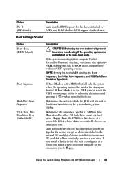
Inside the System (2.5-Inch Hard-Drive Chassis) 6 5 4 3 2 1 7 8 9 16 15 14 13 12 10 11 1 USB connector for optional internal USB key 3 hot-swappable cooling fans (4 or 5) 5 processors (1 or 2) 7 riser 2 (PCIe slots 3 ... 4 memory modules (up to 18 total, 9 for each processor) 6 power supply bays (2) 8 riser 1 (PCIe slots 1 and 2) 10 integrated storage controller card 12 SAS or SATA hard drives (up to 8) 14 flex bay for optional tape backup unit 16 slimline optical...
Inside the System (2.5-Inch Hard-Drive Chassis) 6 5 4 3 2 1 7 8 9 16 15 14 13 12 10 11 1 USB connector for optional internal USB key 3 hot-swappable cooling fans (4 or 5) 5 processors (1 or 2) 7 riser 2 (PCIe slots 3 ... 4 memory modules (up to 18 total, 9 for each processor) 6 power supply bays (2) 8 riser 1 (PCIe slots 1 and 2) 10 integrated storage controller card 12 SAS or SATA hard drives (up to 8) 14 flex bay for optional tape backup unit 16 slimline optical...
Hardware Manual
Page 77
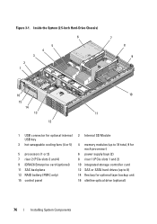
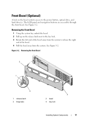
... latch next to the key lock. 3 Rotate the left end of the bezel. 4 Pull the bezel away from the system to the power button, optical drive, and hard drive(s). See Figure 3-2. Removing the Front Bezel 2 1 4 1 release latch 3 hinge tabs 3 2 bezel 4 key lock Installing System Components 77 Figure 3-2. The LCD panel and navigation buttons...
... latch next to the key lock. 3 Rotate the left end of the bezel. 4 Pull the bezel away from the system to the power button, optical drive, and hard drive(s). See Figure 3-2. Removing the Front Bezel 2 1 4 1 release latch 3 hinge tabs 3 2 bezel 4 key lock Installing System Components 77 Figure 3-2. The LCD panel and navigation buttons...
Hardware Manual
Page 80
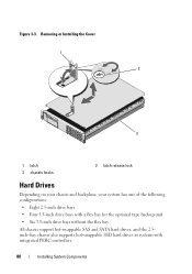
Removing or Installing the Cover 1 2 3 1 latch 3 chassis hooks 2 latch release lock Hard Drives Depending on your chassis and backplane, your system has one of the following configurations: • Eight 2.5-inch drive bays • Four 3.5-inch drive bays with a flex bay for the optional tape backup unit • Six 3.5-inch drive bays without the flex bay All chassis support hot-swappable SAS and SATA hard drives, and the 2.5inch-bay chassis also supports hot-swappable SSD hard drives in systems with integrated PERC controllers. 80 Installing System Components Figure 3-3.
Removing or Installing the Cover 1 2 3 1 latch 3 chassis hooks 2 latch release lock Hard Drives Depending on your chassis and backplane, your system has one of the following configurations: • Eight 2.5-inch drive bays • Four 3.5-inch drive bays with a flex bay for the optional tape backup unit • Six 3.5-inch drive bays without the flex bay All chassis support hot-swappable SAS and SATA hard drives, and the 2.5inch-bay chassis also supports hot-swappable SSD hard drives in systems with integrated PERC controllers. 80 Installing System Components Figure 3-3.
Hardware Manual
Page 81
... lever on the right side, and slide the blank out until it is configured correctly to support hot-swap drive removal and insertion. Hard drives are supplied in special hotswappable hard-drive carriers that fit in the 3.5-inch-bay chassis only. CAUTION: Do not turn off or reboot your system while... the drive is running, see "Front-Panel Features and Indicators"). The remaining hard drives must be 3.5 inches in size and must be completed. Installing System Components 81 Be aware that the ...
... lever on the right side, and slide the blank out until it is configured correctly to support hot-swap drive removal and insertion. Hard drives are supplied in special hotswappable hard-drive carriers that fit in the 3.5-inch-bay chassis only. CAUTION: Do not turn off or reboot your system while... the drive is running, see "Front-Panel Features and Indicators"). The remaining hard drives must be 3.5 inches in size and must be completed. Installing System Components 81 Be aware that the ...
Hardware Manual
Page 82
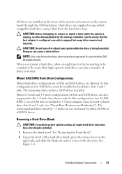
... Front Bezel." 2 From the RAID management software, prepare the drive for information about hot-swap drive removal. 82 Installing System Components Wait until the release lever clicks into place. Removing and Installing a Hard Drive Blank 1 2 3 3 1 3.5-in hard drive blank 3 release latch 2 2.5-in hard drive blank Installing a Hard-Drive Blank Align the hard-drive blank with your operating system for more information. 1 If...
... Front Bezel." 2 From the RAID management software, prepare the drive for information about hot-swap drive removal. 82 Installing System Components Wait until the release lever clicks into place. Removing and Installing a Hard Drive Blank 1 2 3 3 1 3.5-in hard drive blank 3 release latch 2 2.5-in hard drive blank Installing a Hard-Drive Blank Align the hard-drive blank with your operating system for more information. 1 If...
Hardware Manual
Page 83
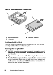
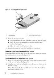
... fully installed. See "Removing the Front Bezel." 2 If a drive blank is powered down. Installing a Hot-Swap Hard Drive CAUTION: When installing a hard drive, ensure that your operating system. 1 If present, remove the front bezel. Drive Blank." See "Installing a Hard-Drive Blank." 6 If applicable, install the bezel. See "Removing a Hard- If the drive has been online, the green activity/fault indicator...
... fully installed. See "Removing the Front Bezel." 2 If a drive blank is powered down. Installing a Hot-Swap Hard Drive CAUTION: When installing a hard drive, ensure that your operating system. 1 If present, remove the front bezel. Drive Blank." See "Installing a Hard-Drive Blank." 6 If applicable, install the bezel. See "Removing a Hard- If the drive has been online, the green activity/fault indicator...
Hardware Manual
Page 84
... bezel. Installing a Hard Drive Into a Hard-Drive Carrier 1 Insert the hard drive into the drive bay until the carrier contacts the backplane. See Figure 3-6. 2 Align the screw holes on the hard drive carrier. Removing a Hard Drive From a Hard-Drive Carrier Remove the screws from the slide rails on the front of the drive at the back. b Insert the hard-drive carrier into the hard-drive carrier with the...
... bezel. Installing a Hard Drive Into a Hard-Drive Carrier 1 Insert the hard drive into the drive bay until the carrier contacts the backplane. See Figure 3-6. 2 Align the screw holes on the hard drive carrier. Removing a Hard Drive From a Hard-Drive Carrier Remove the screws from the slide rails on the front of the drive at the back. b Insert the hard-drive carrier into the hard-drive carrier with the...
Hardware Manual
Page 85
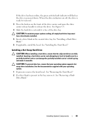
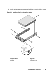
Installing a Hard Drive into a Drive Carrier 3 2 1 4 1 hard-drive carrier 3 hard drive 2 screws (4) 4 SAS screw hole Installing System Components 85 3 Attach the four screws to secure the hard drive to the hard-drive carrier. Figure 3-6.
Installing a Hard Drive into a Drive Carrier 3 2 1 4 1 hard-drive carrier 3 hard drive 2 screws (4) 4 SAS screw hole Installing System Components 85 3 Attach the four screws to secure the hard drive to the hard-drive carrier. Figure 3-6.
Hardware Manual
Page 106
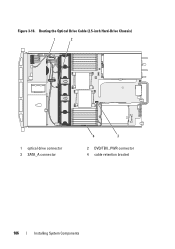
Routing the Optical Drive Cable (2.5-inch Hard-Drive Chassis) 1 2 1 optical drive connector 3 SATA_A connector 4 3 2 DVD/TBU_PWR connector 4 cable retention bracket 106 Installing System Components Figure 3-16.
Routing the Optical Drive Cable (2.5-inch Hard-Drive Chassis) 1 2 1 optical drive connector 3 SATA_A connector 4 3 2 DVD/TBU_PWR connector 4 cable retention bracket 106 Installing System Components Figure 3-16.


